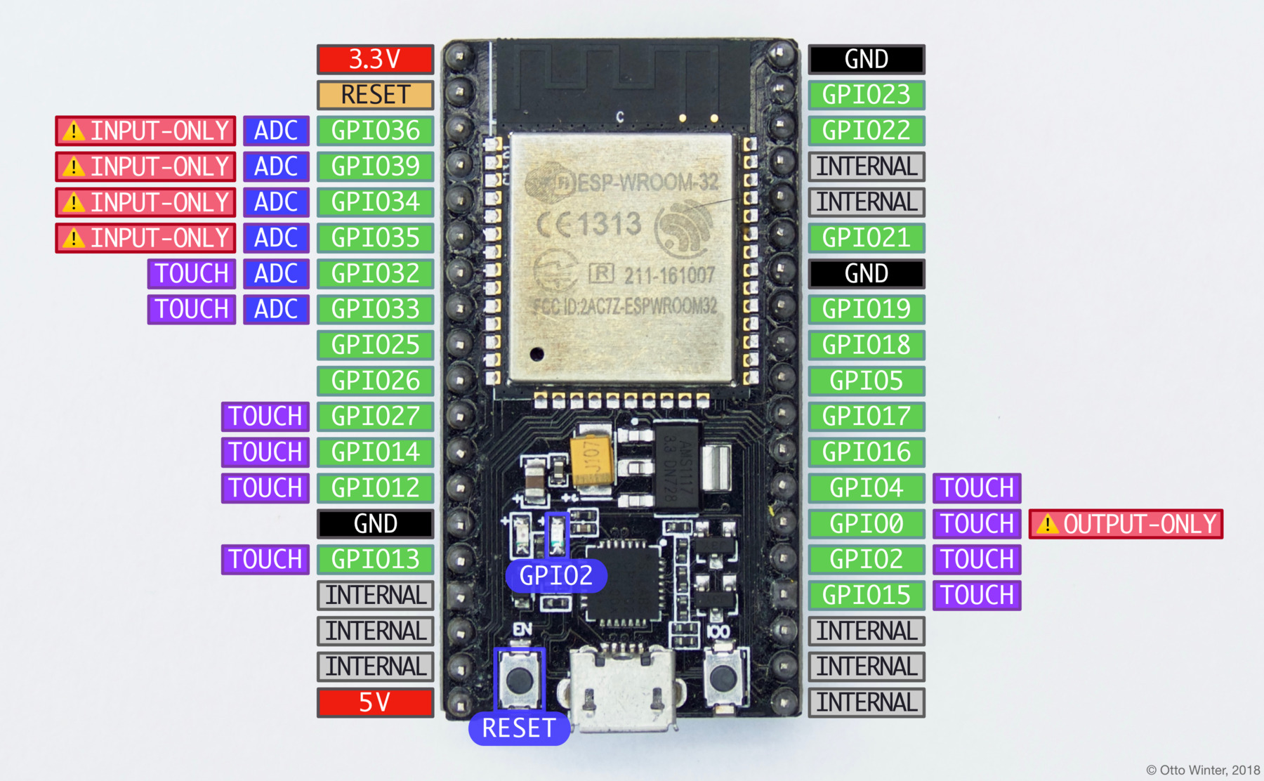
ESP32 NodeMCU
ESP32 Docs ESP32 Home ESP8266 Home Generic
Generic 2 Getting Started Getting 3 Get Date Time
Getting Started DevBoard ESP32 Pinout.html Install ESP32 on IDE Troubleshooting Guide
Config NTP Client NodeMcu ESP32 Libs Useful WiFi Stuff Features
ESP32 basic ESP32 WiFi Funcs System Time ESP32 Pgm Get DateTime via ESP32
ESP32 DeepSleep Wake Srcs Get Started ESP32 Dev ESP Time ESP Time Zones
DS3231 Clock Instructions DS3231 Datasheet TCX0 MAXIM NTP Intro
ESP32 Daasheet NodeMCU-32s Datasheet ESP32S Datasheet Wroom ESP32S Registers
ESP32 Datasheet ESP32 Web Server
Interrupts
ESP32 Interrupts Install ESP32 Board in IDE ESP32 Interrupts Create ESP32 Interrupts
ESP32 Interrupt Tut Configu
Events System Events
WiFi
Conn To WiFi
Touch Sensors
Touch Sensors
Weather Station Info
Weather Station Weather Station HTML Page Weather Station Code

ESPRESSIF DOCS
Pgmming Guide Espressif Site


ESP32 Internal Registers Etc.
Register Table Address Map I² Interface Clock & Calendar


ESP32 Registers
Address Bit 7 MSB Bit 6 Bit 5 Bit 4 Bit 3 Bit 2 Bit 1 Bit 0 LSB Function Range
00h010 SecsSecsSeconds00-59
01h010 MInsMinsMinutes 00-59
02h012,*24*AM, PM10 HourHourHours1-12 + *AM,PM 0-23
03h00000Day O WeekDay1-7
04h0010 DateDateDate01-31
05hCentury0010 MonthMonthMonth/Century01-12 Century
06h10 YearYearYear00-99
07hA1M110 SecondsSecondsAlarm 1 Secs00-59
08hA1M210 MinutesMinutesAlarm1 Mins0-59
09h A1M3 12, *24 *AM,PM 10 HourHour Alarm 1 Hours1-12 + *AM,PM
20 Hour0-23
0Ah A1M4 Dy,Dt 10 Date Day Alarm 1 Day 1-7
DateAlarm 1 Date1-31
0Bh A2M2 10 Minues Minutes Alarm2 Minutes 0-59
0Ch A2M3 12,*24 *AM,PM 10 Hour Hour Alarm 2 Hours 1-12 + *AM,PM 00-23
20 Hour
0Dh A2M4 12 *DT 10 Date Day Alarm 2 Day 1-7
DateAlarm 2 Date1-31
0Eh*EOSCBBSQWCONVRS2RS1INTCNA2IEA1IEControl -
0FhOSF000EN32kHzBSYA2FA1FControl/Status-
10hSIGNDATADATADATADATADATADATADATAAging Offset-
11hSIGNDATADATADATADATADATADATADATAMSB of Temp-
12hDATADATA000000LSB of Temp-


Address Map
Figure 1 shows the address map for the DS3231 time- keeping registers. During a multibyte access, when the address pointer reaches the end of the register space (12h), it wraps around to location 00h. On an I 2 C START or address pointer incrementing to location 00h, the cur- rent time is transferred to a second set of registers. The time information is read from these secondary registers, while the clock may continue to run. This eliminates the need to reread the registers in case the main registers update during a read.


I 2 C Interface
The I 2 C interface is accessible whenever either V CC or V BAT is at a valid level. If a microcontroller connected www.maximintegrated.com to the DS3231 resets because of a loss of V CC or other event, it is possible that the microcontroller and DS3231 I 2 C communications could become unsynchronized, e.g., the microcontroller resets while reading data from the DS3231. When the microcontroller resets, the DS3231 I 2 C interface may be placed into a known state by tog- gling SCL until SDA is observed to be at a high level. At that point the microcontroller should pull SDA low while SCL is high, generating a START condition.


Clock and Calendar
The time and calendar information is obtained by reading the appropriate register bytes. Figure 1 illustrates the RTC registers. The time and calendar data are set or initialized by writing the appropriate register bytes. The contents of the time and calendar registers are in the binary-coded decimal (BCD) format. The DS3231 can be run in either 12-hour or 24-hour mode. Bit 6 of the hours register is defined as the 12- or 24-hour mode select bit. When high, the 12-hour mode is selected. In the 12-hour mode, bit 5 is the AM/PM bit with logic-high being PM. In the 24-hour mode, bit 5 is the 20-hour bit (20–23 hours). The century bit (bit 7 of the month register) is toggled when the years register overflows from 99 to 00. The day-of-week register increments at midnight. Values that correspond to the day of week are user-defined but must be sequential (i.e., if 1 equals Sunday, then 2 equals Monday, and so on). Illogical time and date entries result in undefined operation. When reading or writing the time and date registers, sec- ondary (user) buffers are used to prevent errors when the internal registers update. When reading the time and date registers, the user buffers are synchronized to the internal registers on any START and when the register pointer rolls over to zero. The time information is read from these secondary registers, while the clock continues to run. This eliminates the need to reread the registers in case the main registers update during a read. The countdown chain is reset whenever the seconds register is written. Write transfers occur on the acknowl- edge from the DS3231. Once the countdown chain is reset, to avoid rollover issues the remaining time and date registers must be written within 1 second. The 1Hz square-wave output, if enabled, transitions high 500ms after the seconds data transfer, provided the oscillator is already running.