ESP32 Web Server – Arduino IDE
In this project you’ll create a standalone web server with an ESP32 that
controls outputs (two LEDs) using the Arduino IDE programming environment. The
web server is mobile responsive and can be accessed with any device that as a
browser on the local network. We’ll show you how to create the web server and
how the code works step-by-step.
 If you want to learn more about the ESP32, read Getting Started Guide with ESP32.
Watch the Video Tutorial
This tutorial is available in video format (watch below) and in written format
(continue reading this page).
If you want to learn more about the ESP32, read Getting Started Guide with ESP32.
Watch the Video Tutorial
This tutorial is available in video format (watch below) and in written format
(continue reading this page).
Project Overview
Before going straight to the project, it is important to outline what our web
server will do, so that it is easier to follow the steps later on.
The web server you’ll build controls two LEDs connected to the ESP32 GPIO 26 and GPIO 27;
You can access the ESP32 web server by typing the ESP32 IP address on a
browser in the local network;
By clicking the buttons on your web server you can instantly change the
state of each LED.
This is just a simple example to illustrate how to build a web server that
controls outputs, the idea is to replace those LEDs with a relay, or any other
electronic components you want.
Installing the ESP32 board in Arduino IDE
There’s an add-on for the Arduino IDE that allows you to program the ESP32 using
the Arduino IDE and its programming language. Follow one of the following
tutorials to prepare your Arduino IDE:
Parts Required
For this tutorial you’ll need the following parts:
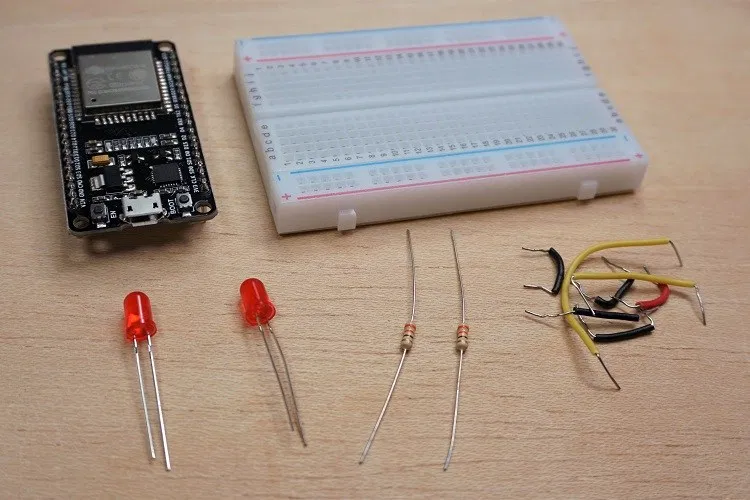 ESP32 development board – read ESP32 Development Boards Review and Comparison
2x 5mm LED
2x 330 Ohm resistor
Breadboard
Jumper wires
You can use the preceding links or go directly to MakerAdvisor.com/tools to find all the parts for your projects at the best price!
ESP32 development board – read ESP32 Development Boards Review and Comparison
2x 5mm LED
2x 330 Ohm resistor
Breadboard
Jumper wires
You can use the preceding links or go directly to MakerAdvisor.com/tools to find all the parts for your projects at the best price!
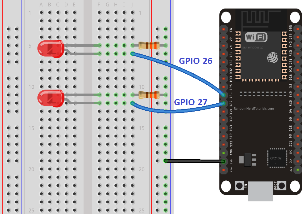
Schematic
Start by building the circuit. Connect two LEDs to the ESP32 as shown in the
following schematic diagram – one LED connected to GPIO 26, and the other to GPIO 27.
Note: We’re using the ESP32 DEVKIT DOIT board with 36 pins. Before assembling
the circuit, make sure you check the pinout for the board you’re using.
ESP32 Web Server Code
Here we provide the code that creates the ESP32 web server. Copy the following
code to your Arduino IDE, but don’t upload it yet. You need to make some changes
to make it work for you.
/*H*******************************************************
Rui Santos
Complete project details at https://randomnerdtutorials.com
**********************************************************/
#include <WiFi.h> // Load Wi-Fi library
//************************* DEFINES ************************************
#define BAUD 9600
const char* ssid = "REPLACE_WITH_YOUR_SSID";
const char* password = "REPLACE_WITH_YOUR_PASSWORD";
const int Out26 = 26; // ASSIGN OUTPUT VARIABLES TO GPIO PINS
const int Out27 = 27;
typedef unsigned long ulong;
//************************* PROTOTYPES ************************************
//************************* VARIABLES ************************************
WiFiServer Srv( 80 ); // SET WEB SERVER PORT NUMBER TO 80
String Hdr; // HTTP REQUEST
String Out26State = "off"; // CURRENT OUTPUT STATE
String Out27State = "off";
ulong CurrTim = millis(); // CURRENT TIME
ulong PrevTim = 0; // PREVIOUS TIME
const long TimOut = 2000; // TimOut TIME IN Ms (EXAMPLE: 2000Ms = 2s)
/*F********************************************************************
*
**********************************************************************/
void
setup()
{
Serial.begin( BAUD );
pinMode( Out26, OUTPUT ); // INIT OUTPUT VARIABLES AS OUTPUTS
pinMode( Out27, OUTPUT );
digitalWrite( Out26, LOW ); // SET OUTPUTS TO LOW
digitalWrite( Out27, LOW );
Serial.print( "Connecting to " );
Serial.println( ssid ); // CONNECT TO Wi-Fi NETWORK WITH SSID AND PSWD
WiFi.begin( ssid, password );
while( WiFi.status() != WL_CONNECTED )
{
delay( 500 );
Serial.print( "." );
}
Serial.println( "" ); // PRINT LOCAL IP ADDRESS AND START WEB SERVER
Serial.println( "WiFi connected." );
Serial.println( "IP address: " );
Serial.println( WiFi.localIP() );
Srv.begin();
}
/*F********************************************************************
*
**********************************************************************/
void
loop()
{
char chr;
String currLin = "" ;// MAKE STRING FOR INCOMING DATA FROM CLIENT
WiFiClient clnt;
if( clnt = Srv.available()) // INCOMING CLIENT
{ // NEW CLIENT CONNECTS
CurrTim = millis();
PrevTim = CurrTim;
Serial.println( "New Client." ); // PRINT A MESSAGE ON SERIAL PORT
currLin = "" ;// MAKE STRING FOR INCOMING DATA FROM CLIENT
while( clnt.connected() && CurrTim - PrevTim <= TimOut)
{ // LOOP WHILE CLIENT'S CONNECTED
CurrTim = millis();
if( clnt.available() )
{ // IF THERE'S BYTES TO READ FROM CLIENT,
chr = clnt.read(); // READ A BYTE, THEN
Serial.write( chr ); // PRINT ON SERIAL MONITOR
Hdr += chr;
if( chr == '\n') // BYTE IS A NEWLINE CHARACTER
{ // TWO NEWLINE CHARACTERS IN A ROW == CURRENT LINE BLANK
// END OF CLIENT HTTP REQUEST, SEND RESPONSE:
if( currLin.length() == 0 )
{ // HTTP HEADERS ALWAYS START WITH A RESPONSE CODE
// (e.g. HTTP/1.1 200 OK) AND CONTENT-TYPE SO CLIENT KNOWS WHAT'S COMING
// , THEN A BLANK LINE:
clnt.println( "HTTP/1.1 200 OK" );
clnt.println( "Content-type:text/html" );
clnt.println( "Connection: close" );
clnt.println(); // SET GPIO ON OR OFF
if( Hdr.indexOf( "GET /26/on") >= 0)
{
Serial.println( "GPIO 26 on" );
Out26State = "on";
digitalWrite( Out26, HIGH );
}
else if( Hdr.indexOf( "GET /26/off") >= 0)
{
Serial.println( "GPIO 26 off");
Out26State = "off";
digitalWrite( Out26, LOW );
}
else if( Hdr.indexOf( "GET /27/on" ) >= 0)
{
Serial.println( "GPIO 27 on" );
Out27State = "on";
digitalWrite( Out27, HIGH );
}
else if( Hdr.indexOf( "GET /27/off" ) >= 0)
{
Serial.println( "GPIO 27 off" );
Out27State = "off";
digitalWrite( Out27, LOW );
}
// DISPLAY HTML WEB PAGE
clnt.println( "<DOCTYPE html><html>
clnt.println( "<head><meta name=\"viewport\""
" content=\"width=device-width, initial-scale=1\">
clnt.println( "<link rel=\"icon\" href=\"data:,\">"
"");
// CSS STYLE ON/OFF BUTTONS OK TO CHANGE background-color AND font-size
clnt.println( "<style>html"
" { font-family: Helvetica; display: inline-block;"
" margin: 0px auto; text-align: center;}");
clnt.println( ".button { background-color: #4CAF50;"
" border: none; color: white; padding: 16px 40px;");
clnt.println( "text-decoration: none; font-size:"
" 30px; margin: 2px; cursor: pointer;}");
clnt.println( ".button2 {background-color: #555555;"
"}<style><head>
clnt.println( "<body><h1>ESP32 Web "
"Server<h1> // WEB PAGE HEADING
// DSPLY CURR STATE, BUTTONS GPIO 26
clnt.println( "<p>GPIO 26 - State " "
"+ Out26State + "<p>
if( Out26State == "off" )
{ // OUTPUT26sTATE IS OFF, IT DISPLAY ON BUTTON
clnt.println( "<p><a href=\"/26/on\">"
"<button class=\"button\">ON<button>"
"<a><p>
}
else
{
clnt.println( "<p><a href=\"/26/off\">"
"<button class=\"button button2\">"
"OFF<button><a><p>
}
// DSPLY CURR BUTTONS: GPIO 27
clnt.println( "<p>GPIO 27 - State " +
Out27State + "<p>
// IF OUTPUT27sTATE OFF, DISPLAY ON BUTTON
if( Out27State == "off" )
{
clnt.println( "<p><a href=\"/27/on\">"
"<button class=\"button\">ON"
"<button><a><p>
}
else
{
clnt.println( "<p><a href=\"/27/off\">"
"<button class=\"button button2\">OFF"
"<button><a><p>
}
clnt.println( "</body></html>
// HTTP RESPONSE ENDS WITH BLANK LINE (DOUBLE NL)
clnt.println();
break; // BREAK OUT OF WHILE LOOp
}
else // IF NEWLINE, CLR CURR LINE
currLin = "";
}
else if( chr != '\r') // IF ANYTHING ELSE BUT NL CHARACTER
currLin += chr; // ADD IT TO THE END OF CURRENTlINE
}
}
Hdr = ""; // CLEAR HEADER VARIABLE
clnt.stop(); // CLOSE CONNECTION
Serial.println( "Client disconnected." );
Serial.println( "" );
}
}
View raw code
Setting Your Network Credentials
You need to modify the following lines with your network credentials: SSID and password. The code is well commented on where you should make the changes.
// Replace with your network credentials
const char* ssid = "REPLACE_WITH_YOUR_SSID";
const char* password = "REPLACE_WITH_YOUR_PASSWORD";
Uploading the Code
Now, you can upload the code and and the web server will work straight away. Follow the next steps to upload code to the ESP32:
1) Plug your ESP32 board in your computer;
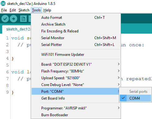
2) In the Arduino IDE select your board in Tools > Board (in our case we’re
using the ESP32 DEVKIT DOIT board);
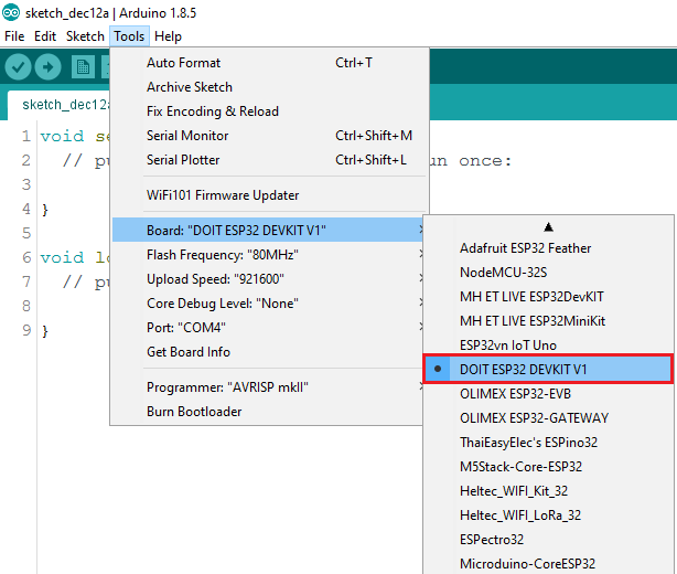 3) Select the COM port in Tools > Port.
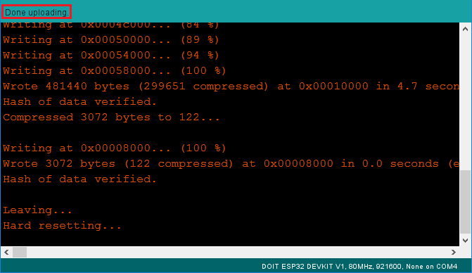
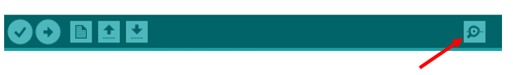
 4) Press the Upload button in the Arduino IDE and wait a few seconds while the code compiles and uploads to your board.
5) Wait for the “Done uploading” message.
4) Press the Upload button in the Arduino IDE and wait a few seconds while the code compiles and uploads to your board.
5) Wait for the “Done uploading” message.
Finding the ESP IP Address
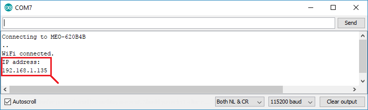
After uploading the code, open the Serial Monitor at a baud rate of 115200.
 Press the ESP32 EN button (reset). The ESP32 connects to Wi-Fi, and outputs the
ESP IP address on the Serial Monitor. Copy that IP address, because you need it
to access the ESP32 web server.
Press the ESP32 EN button (reset). The ESP32 connects to Wi-Fi, and outputs the
ESP IP address on the Serial Monitor. Copy that IP address, because you need it
to access the ESP32 web server.
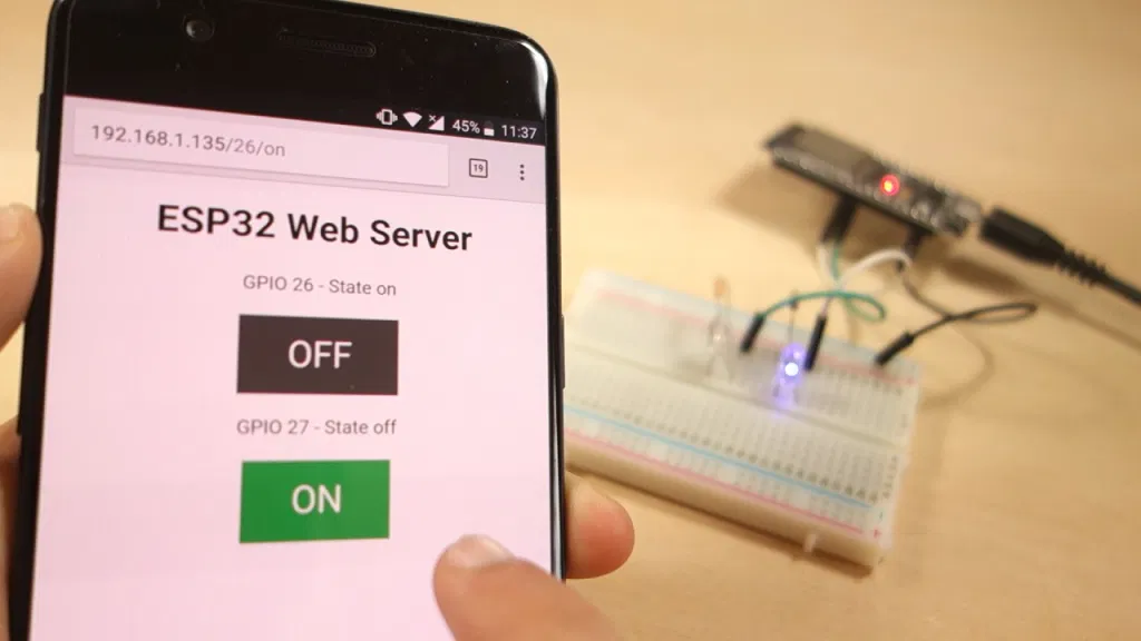
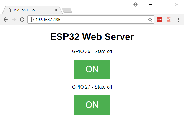
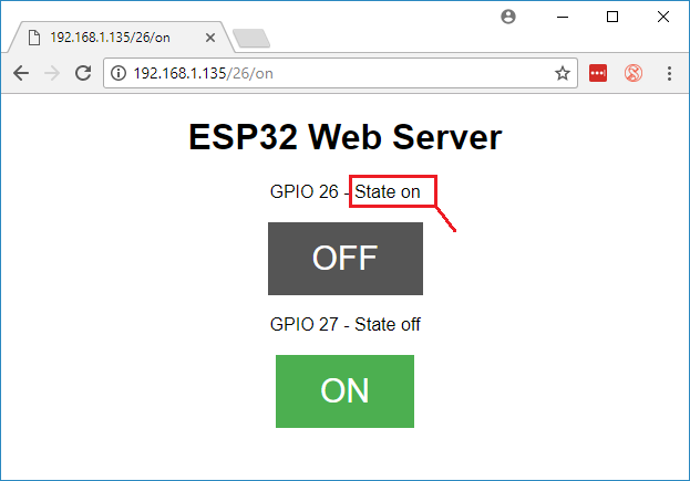
Accessing the Web Server
To access the web server, open your browser, paste the ESP32 IP address, and
you’ll see the following page. In our case it is 192.168.1.135.
 If you take a look at the Serial Monitor, you can see what’s happening on the
background. The ESP receives an HTTP request from a new client (in this case,
your browser).
If you take a look at the Serial Monitor, you can see what’s happening on the
background. The ESP receives an HTTP request from a new client (in this case,
your browser).
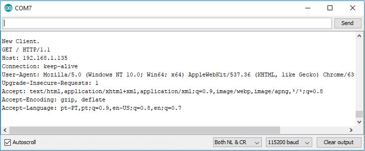 You can also see other information about the HTTP request.
Testing the Web Server
Now you can test if your web server is working properly. Click the buttons to control the LEDs.
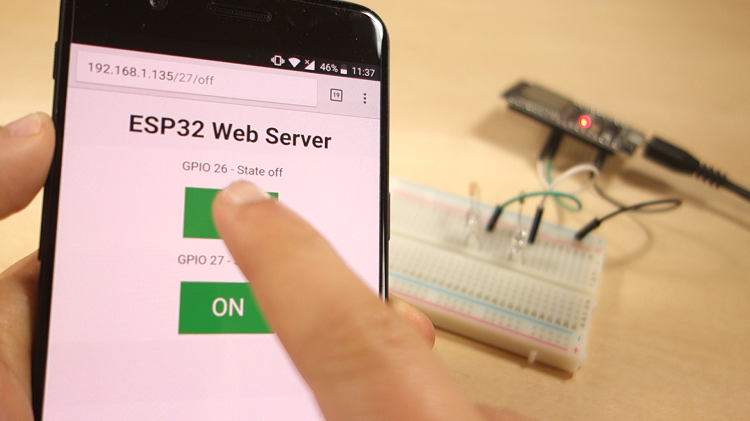 At the same time, you can take a look at the Serial Monitor to see what’s going
on in the background. For example, when you click the button to turn GPIO 26 ON,
ESP32 receives a request on the /26/on URL.
At the same time, you can take a look at the Serial Monitor to see what’s going
on in the background. For example, when you click the button to turn GPIO 26 ON,
ESP32 receives a request on the /26/on URL.
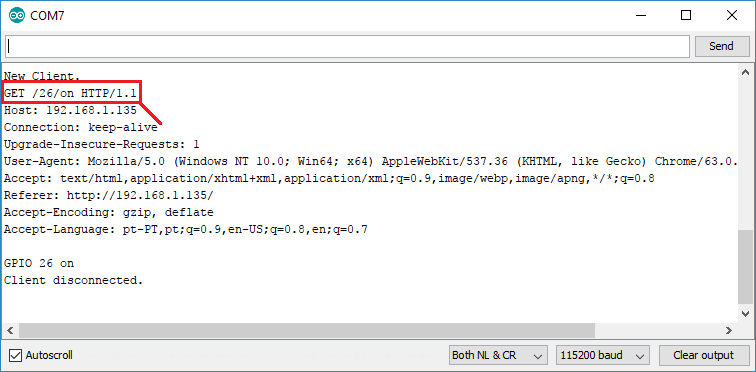 When the ESP32 receives that request, it turns the LED attached to GPIO 26 ON
and updates its state on the web page.
When the ESP32 receives that request, it turns the LED attached to GPIO 26 ON
and updates its state on the web page.
 The button for GPIO 27 works in a similar way. Test that it is working properly.
How the Code Works
In this section will take a closer look at the code to see how it works.
The first thing you need to do is to include the WiFi library.
#include <WiFi.h>
As mentioned previously, you need to insert your ssid and password in the following lines inside the double quotes.
const char* ssid = "";
const char* password = "";
Then, you set your web server to port 80.
WiFiServer server(80);
The following line creates a variable to store the header of the HTTP request:
String header;
Next, you create auxiliar variables to store the current state of your outputs. If you want to add more outputs and save its state, you need to create more variables.
String output26State = "off";
String output27State = "off";
You also need to assign a GPIO to each of your outputs. Here we are using
GPIO 26 and GPIO 27. You can use any other suitable GPIOs.
const int output26 = 26;
const int output27 = 27;
setup()
Now, let’s go into the setup(). First, we start a serial communication at a baud rate of 115200 for debugging purposes.
Serial.begin( 115200 );
You also define your GPIOs as OUTPUTs and set them to LOW.
// INITIALIZE OUTPUT VARIABLES AS OUTPUTS
pinMode( output26, OUTPUT );
pinMode( output27, OUTPUT );
// Set outputs to LOW
digitalWrite( output26, LOW );
digitalWrite( output27, LOW );
The following lines begin the Wi-Fi connection with WiFi.begin(ssid, password),
wait for a successful connection and print the ESP IP address in the Serial
Monitor.
// CONNECT TO Wi-Fi NETWORK WITH SSID AND PASSWORD
Serial.print( "Connecting to " );
Serial.println( ssid );
WiFi.begin( ssid, password );
while( WiFi.status() != WL_CONNECTED )
{
delay( 500 );
Serial.print( "." );
}
// Print local IP address and start web server
Serial.println( "" );
Serial.println( "WiFi connected." );
Serial.println( "IP address: " );
Serial.println( WiFi.localIP() );
server.begin();
loop()
In the loop() we program what happens when a new client establishes a connection
with the web server.
The ESP32 is always listening for incoming clients with the following line:
WiFiClient client = server.available(); // Listen for incoming clients
When a request is received from a client, we’ll save the incoming data. The
while loop that follows will be running as long as the client stays connected.
We don’t recommend changing the following part of the code unless you know
exactly what you are doing.
if( client )
{ // IF A NEW CLIENT CONNECTS,
Serial.println( "New Client." ); // PRINT A MESSAGE OUT IN THE SERIAL PORT
String currentLine = ""; // MAKE A String TO HOLD INCOMING DATA FROM CLIENT
while( client.connected() ) // LOOP WHILE CLIENT'S CONNECTED
{
if( client.available() )
{ // IF THERE'S BYTES TO READ FROM THE CLIENT,
char c = client.read(); // READ A BYTE, THEN
Serial.write( c ); // PRINT IT OUT SERIAL MONITOR
header += c;
if( c == '\n')
{ // IF BYTE IS A NEWLINE CHARACTER
// IF CURRENT LINE IS BLANK, YOU GOT TWO NEWLINE CHARACTERS IN A ROW.
/ THAT'S END OF CLIENT HTTP REQUEST, SO SEND RESPONSE:
if( currentLine.length() == 0 )
{
// HTTP HEADERS ALWAYS START WITH A RESPONSE CODe (e.g. HTTP/1.1 200 OK)
// AND A CONTENT-TYPE SO THE CLIENT KNOWS WHAT'S COMING, THEN A BLANK
// LINE:
client.println( "HTTP/1.1 200 OK" );
client.println( "Content-type:text/html" );
client.println( "Connection: close" );
client.println();
The next section of if and else statements checks which button was pressed in
your web page, and controls the outputs accordingly. As we’ve seen previously,
we make a request on different URLs depending on the button pressed.
// TURNS GPIOs ON AND OFF
if( header.indexOf( "GET /26/on" ) >= 0 )
{
Serial.println("GPIO 26 on");
output26State = "on";
digitalWrite(output26, HIGH);
}
else if( header.indexOf( "GET /26/off" ) >= 0 )
{
Serial.println( "GPIO 26 off" );
output26State = "off";
digitalWrite( output26, LOW );
}
else if( header.indexOf( "GET /27/on") >= 0)
{
Serial.println( "GPIO 27 on" );
output27State = "on";
digitalWrite( output27, HIGH );
} else if( header.indexOf("GET /27/off") >= 0)
{
Serial.println( "GPIO 27 off" );
output27State = "off";
digitalWrite( output27, LOW );
}
For example, if you’ve press the GPIO 26 ON button, the ESP32 receives a request
on the /26/ON URL (we can see that that information on the HTTP header on the
Serial Monitor). So, we can check if the header contains the expression
GET /26/on. If it contains, we change the output26state variable to ON, and the
ESP32 turns the LED on.
This works similarly for the other buttons. So, if you want to add more outputs,
you should modify this part of the code to include them.
Displaying the HTML web page
The next thing you need to do, is creating the web page. The ESP32 will be
sending a response to your browser with some HTML code to build the web page.
The web page is sent to the client using this expressing client.println(). You
should enter what you want to send to the client as an argument.
The first thing we should send is always the following line, that indicates that
we are sending HTML.
<DOCTYPE HTML><html>
Then, the following line makes the web page responsive in any web browser.
client.println("<head><meta name=\"viewport\" content=\"width=device-width
, initial-scale=1\">");
And the following is used to prevent requests on the favicon. – You don’t need
to worry about this line.
client.println("<link rel=\"icon\" href=\"data:,\">
Styling the Web Page
Next, we have some CSS text to style the buttons and the web page appearance.
We choose the Helvetica font, define the content to be displayed as a block and
aligned at the center.
client.println( "<style>html { font-family: Helvetica; display: inline-block; margin: 0px auto; text-align: center;}" );
We style our buttons with the #4CAF50 color, without border, text in white color
, and with this padding: 16px 40px. We also set the text-decoration to none,
define the font size, the margin, and the cursor to a pointer.
client.println(".button { background-color: #4CAF50; border: none; color: white; padding: 16px 40px;");
client.println("text-decoration: none; font-size: 30px; margin: 2px; cursor: pointer;}");
We also define the style for a second button, with all the properties of the
button we’ve defined earlier, but with a different color. This will be the
style for the off button.
client.println(".button2 {background-color: #555555;}<style>lt;head>
Setting the Web Page First Heading
In the next line you can set the first heading of your web page. Here we have
“ESP32 Web Server”, but you can change this text to whatever you like.
// Web Page Heading
client.println("<h1>ESP32 Web Server<h1>
Displaying the Buttons and Corresponding State
Then, you write a paragraph to display the GPIO 26 current state.
As you can see we use the output26State variable, so that the state updates
instantly when this variable changes.
client.println("<p>GPIO 26 - State " + output26State + "<p>
Then, we display the on or the off button, depending on the current state of
the GPIO. If the current state of the GPIO is off, we show the ON button, if
not, we display the OFF button.
if( output26State == "off" )
client.println( "<p>lt;a href=\"/26/on\">button class=\"button\""
">ON<button>lt;a>lt;p>
else
client.println( "<p>lt;a href=\"/26/off\">lt;button class=\""
"button button2\">OFF<button>lt;a>lt;p>
}
We use the same procedure for GPIO 27.
Closing the Connection
Finally, when the response ends, we clear the header variable, and stop the
connection with the client with client.stop().
header = ""; // CLEAR HEADER VARIABLE
client.stop(); // CLOSE CONNECTION
Wrapping Up
In this tutorial we’ve shown you how to build a web server with the ESP32.
We’ve shown you a simple example that controls two LEDs, but the idea is to
replace those LEDs with a relay, or any other output you want to control. For
more projects with ESP32, check the following tutorials:
Build an All-in-One ESP32 Weather Station Shield
ESP32 Servo Motor Web Server
Getting Started with ESP32 Bluetooth Low Energy (BLE)
More ESP32 tutorials
This is an excerpt from our course: Learn ESP32 with Arduino IDE. If you like
ESP32 and you want to learn more, we recommend enrolling in Learn ESP32 with
Arduino IDE course.