Configuring & Handling ESP32 GPIO Interrupts In Arduino IDE
Interrupts In ESP32
ESP32 provides up to 32 interrupt slots for each core. Each interrupt has a
certain priority level and can be classified into two types.
Hardware interrupts – These occur in response to an external event. For example,
a GPIO interrupt (when a key is pressed) or a touch interrupt (when touch is
detected).
Software Interrupt – These occur in response to a software instruction. For
example, a simple timer interrupt or a watchdog timer interrupt (when the timer
times out).
ESP32 GPIO Interrupt
In ESP32 we can define an interrupt service routine function that will be called
when the GPIO pin changes its logic level.
All GPIO pins in an ESP32 board can be configured to act as interrupt request inputs.
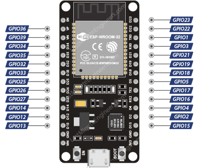 esp32 interrupt pins
Attaching an Interrupt to a GPIO Pin
In the Arduino IDE, we use a function called attachInterrupt() to set an
interrupt on a pin by pin basis. The syntax looks like below.
attachInterrupt( GPIOPin, ISR, Mode );
This function accepts three arguments:
GPIOPin – sets the GPIO pin as the interrupt pin, which tells ESP32 which
pin to monitor.
ISR – is the name of the function that will be called each time the
interrupt occurs.
Mode – defines when the interrupt should be triggered. Five constants are
predefined as valid values:
LOW Triggers interrupt whenever pin is LOW
HIGH Triggers interrupt whenever pin is HIGH
CHANGE Triggers interrupt whenever pin changes value, from
HIGH to LOW or LOW to HIGH
FALLING Triggers interrupt when pin goes from HIGH to LOW
RISING Triggers interrupt when pin goes from LOW to HIGH
Detaching an Interrupt from a GPIO Pin
When you want ESP32 to no longer monitor the pin, you can call the
detachInterrupt() function. The syntax looks like below.
detachInterrupt( GPIOPin );
Interrupt Service Routine
The Interrupt Service Routine (ISR) is a function that is invoked every time an
interrupt occurs on the GPIO pin.
Its syntax looks like below.
/*F********************************************************************
*
**********************************************************************/
void
IRAM_ATTR ISR()
{
Statements;
}
ISRs in ESP32 are special kinds of functions that have some unique rules that
most other functions do not have.
An ISR cannot have any parameters, and they should not return anything.
ISRs should be as short and fast as possible as they block normal program
execution.
They should have the IRAM_ATTR attribute, according to the ESP32 documentation.
What is IRAM_ATTR?
When we flag a piece of code with the IRAM_ATTR attribute, the compiled code is
placed in the ESP32’s Internal RAM (IRAM). Otherwise the code is kept in Flash.
And Flash on ESP32 is much slower than internal RAM.
If the code we want to run is an Interrupt Service Routine (ISR), we generally
want to execute it as soon as possible. If we had to ‘wait’ for the ISR to load
from Flash then things could go horribly wrong.
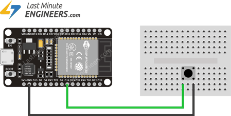
Hardware Hookup
Enough of the theory! Let’s look at a practical example.
Let’s connect a push button to GPIO#18 (D18) on the ESP32. You do not need any
pullup for this pin as we will be pulling the pin up internally.
Example Code: Simple Interrupt
The following sketch demonstrates the use of interrupts and the correct way to
write an interrupt service routine.
/*H********************************************************************
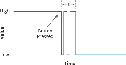
This program watches GPIO#18 (D18) for the FALLING edge. In other words, it
looks for a voltage change going from logic HIGH to logic LOW that occurs when
the button is pressed. When this happens the function isr is called. The code
within this function counts the number of times the button has been pressed.
**********************************************************************/
//************************* DEFINES ************************************
//************************* PROTOTYPES ************************************
void IRAM_ATTR isr();
//************************* VARIABLES ************************************
struct Button {
const uint8_t PIN;
uint32_t numberKeyPresses;
bool pressed;
};
Button button1 = {18, 0, false};
/*F********************************************************************
*
**********************************************************************/
void
setup()
{
Serial.begin(115200);
pinMode(button1.PIN, INPUT_PULLUP);
attachInterrupt(button1.PIN, isr, FALLING);
}
/*F********************************************************************
*
**********************************************************************/
void
loop()
{
if( button1.pressed )
{
Serial.printf( "Button has been pressed %u times\n"
, button1.numberKeyPresses);
button1.pressed = false;
}
}
/*F********************************************************************
*
**********************************************************************/
void IRAM_ATTR
isr()
{
button1.numberKeyPresses++;
button1.pressed = true;
}
Once you have uploaded the sketch, press the EN button on the ESP32 and open the
serial monitor at baud rate 115200. On pressing the button you will get the
following output.
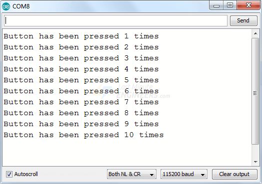 esp32 gpio interrupt output on serial monitor
Code Explanation
At the beginning of the sketch we create a structure called Button. This
structure has three members – the pin number, the number of key presses, and the
pressed state. FYI, a structure is a collection of variables of different types
(but logically related to each other) under a single name.
struct Button {
const uint8_t PIN;
uint32_t numberKeyPresses;
bool pressed;
};
Then create an instance of the Button structure and initialize the pin number to
18, the number of key presses to 0 and the default pressed state to false.
Button button1 = {18, 0, false};
The following code is an interrupt service routine. As mentioned earlier, the
ISR in ESP32 must have the IRAM_ATTR attribute.
In the ISR we simply increment the KeyPresses counter by 1 and set the button
pressed state to True.
/*F********************************************************************
*
**********************************************************************/
void
IRAM_ATTR isr()
{
button1.numberKeyPresses += 1;
button1.pressed = true;
}
In the setup section of the code, we first initialize the serial communication
with the PC and then we enable the internal pullup for the D18 GPIO pin.
Next we tell ESP32 to monitor the D18 pin and to call the interrupt service
routine isr when the pin goes from HIGH to LOW i.e. FALLING edge.
Serial.begin( 115200 );
pinMode( button1.PIN, INPUT_PULLUP );
attachInterrupt( button1.PIN, isr, FALLING );
In the loop section of the code, we simply check if the button has been pressed
and then print the number of times the key has been pressed so far and set the
button pressed state to false so that we can continue to receive interrupts.
if( button1.pressed )
{
Serial.printf( "Button 1 has been pressed %u times\n"
, button1.numberKeyPresses );
button1.pressed = false;
}
Managing Switch Bounce
A common problem with interrupts is that they often get triggered multiple times
for the same event. If you look at the serial output of the above example, you
will notice that even if you press the button only once, the counter is
incremented several times.
 esp32 gpio interrupt bounce problem
 switch bounce signal
Example Code: Debouncing an Interrupt
Here the above sketch is rewritten to demonstrate how to debounce an interrupt
programmatically. In this sketch we allow the ISR to be executed only once on
each button press, instead of executing it multiple times.
Changes to the sketch are highlighted in green.
struct Button {
const uint8_t PIN;
uint32_t numberKeyPresses;
bool pressed;
};
Button button1 = {18, 0, false};
>
//variables to keep track of the timing of recent interrupts
unsigned long button_time = 0;
unsigned long last_button_time = 0;
/*F********************************************************************
*
**********************************************************************/
void IRAM_ATTR
isr()
{
>
button_time = millis();
if( button_time - last_button_time > 250)
{
button1.numberKeyPresses++;
button1.pressed = true;
last_button_time = button_time;
}
}
/*F********************************************************************
*
**********************************************************************/
void
setup()
{
Serial.begin( BAUD );
pinMode( button1.PIN, INPUT_PULLUP );
attachInterrupt( button1.PIN, isr, FALLING );
}
/*F********************************************************************
*
**********************************************************************/
void
loop()
{
if( button1.pressed )
{
Serial.printf( "Button has been pressed %u times\n"
, button1.numberKeyPresses );
button1.pressed = false;
}
}
Let’s look at the serial output again as you press the button. Note that the
ISR is called only once for each button press.
 esp32 gpio interrupt debounce
Code Explanation:
This fix works because each time the ISR is executed, it compares the current
time returned by the millis() function to the time the ISR was last called.
If it is within 250ms, ESP32 ignores the interrupt and immediately goes back to
what it was doing. If not, it executes the code within the if statement
incrementing the counter and updating the last_button_time variable, so the
function has a new value to compare against when it’s triggered in the future.