Build an All-in-One ESP32 Weather Station Shield
In this project I’ll show you how you can build an all-in-one ESP32 weather
station shield and display the sensor readings on a web server. The web server
displays data from all the sensors and automatically updates the readings every
ten seconds, without the need to refresh the web page.
Watch the Video Tutorial and Project Demo
This guide is available in video format (watch below) and in written format
(continue reading).
JLCPCB
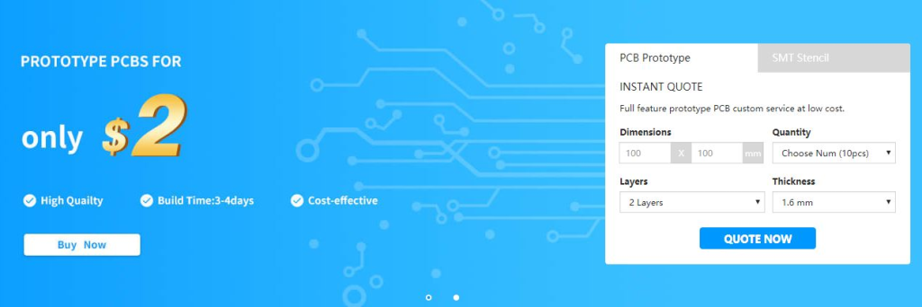
The previous video was sponsored by JLCPCB. JLCPCB is a well known PCB prototype
company in China. It is specialized in quick PCB prototype and small-batch
production. You can order a minimum of 10 PCBs for just $2.
 If you want to turn your breadboard circuits into real boards and make your
projects look more professional, you just have to upload the Gerber files to
order high quality PCBs for low prices. We’ll show you how to do this later in
this blog post.
If you want to turn your breadboard circuits into real boards and make your
projects look more professional, you just have to upload the Gerber files to
order high quality PCBs for low prices. We’ll show you how to do this later in
this blog post.
Resources
You can find all the resources needed to build this project in the bullets below.
Web server code (for Arduino IDE)
HTML page
Schematic diagram
Gerber files
KiCad project to edit the PCB
Click here to download all the files
ESP32 Weather Station Shield
Features
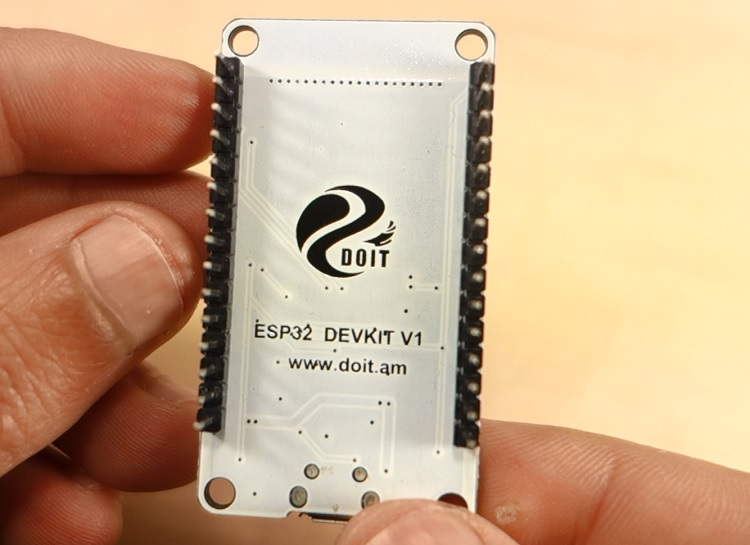
To build this project, I’ve designed a PCB for the ESP32 DEVKIT V1 DOIT board.
The PCB I’ve built only works with the version with 30 GPIOs.
 I’ve designed the shield to be a compact weather station. The PCB has a lot of
features so that it can suit a lot of different projects for different
applications. In fact, I didn’t use all the PCB features in this project.
Additionally, this shield can also be used as a learning shield as it comes with
some of the most used components when starting to learn how to program the ESP32.
I’ve designed the shield to be a compact weather station. The PCB has a lot of
features so that it can suit a lot of different projects for different
applications. In fact, I didn’t use all the PCB features in this project.
Additionally, this shield can also be used as a learning shield as it comes with
some of the most used components when starting to learn how to program the ESP32.
 The shield allows you to control:
2x SMD LEDs
1x Pushbutton
1x Trimpot
1x DHT22 temperature and humidity sensor
1x BMP180 barometric sensor
1x Light dependent resistor
1x MicroSD card module
2x Terminal blocks – that give you access to 3 GPIOs to connect other
components
The microSD card module is a very interesting addition to the shield: it can be
used to store readings if you want to build a data logger, or it can store an
HTML file to serve a web page – as we’ll do in this project. I think this is a
better and easier way to build a web server that requires more complex web pages.
The shield allows you to control:
2x SMD LEDs
1x Pushbutton
1x Trimpot
1x DHT22 temperature and humidity sensor
1x BMP180 barometric sensor
1x Light dependent resistor
1x MicroSD card module
2x Terminal blocks – that give you access to 3 GPIOs to connect other
components
The microSD card module is a very interesting addition to the shield: it can be
used to store readings if you want to build a data logger, or it can store an
HTML file to serve a web page – as we’ll do in this project. I think this is a
better and easier way to build a web server that requires more complex web pages.
ESP32 Shield Pin Assignment
The following table describes the pin assignment for each component on the shield:
Component ESP32 Pin Assignment
Pushbutton GPIO 33
Trimpot GPIO 32
Photoresistor (LDR) GPIO 4
DHT22 data pin GPIO 15
LED1 GPIO 27
LED2 GPIO 26
BMP180 SDA(GPIO 21); SCL(GPIO 22)
SD card module MOSI(GPIO 23); MISO(GPIO 19): CLK(GPIO 18); CS(GPIO 5)
Free GPIOs (terminal blocks) GPIO14, GPIO13, GPIO12
Note: there’s a small problem with our pin assignment. Currently the Arduino
WiFi library uses GPIO 4 that is connected to the LDR. So, you’ll probably have
trouble taking readings from the LDR when you use the WiFi library. To make it
work, you can solder a wire from the LDR to another available GPIO (must support
ADC).
Testing the Circuit on a Breadboard
Before designing the shield, I’ve assembled the circuit on a breadboard. If you don’t want to make a PCB, you can still follow this project by assembling the circuit on a breadboard.
Parts Required
To assemble the circuit on a breadboard you need the following parts:
ESP32 DOIT DEVKIT V1 Board – 30 GPIOs (read ESP32 development boards comparison)
2x 5mm LED
2x 330 Ohm resistor
1x Pushbutton
1x 10k Ohm resistor
1x 10k Ohm potentiometer
1x DHT22 temperature and humidity sensor
1x BMP180
1x MicroSD card module
Breadboard
Jumper wires
You can use the preceding links or go directly to MakerAdvisor.com/tools to find all the parts for your projects at the best price!
Schematic
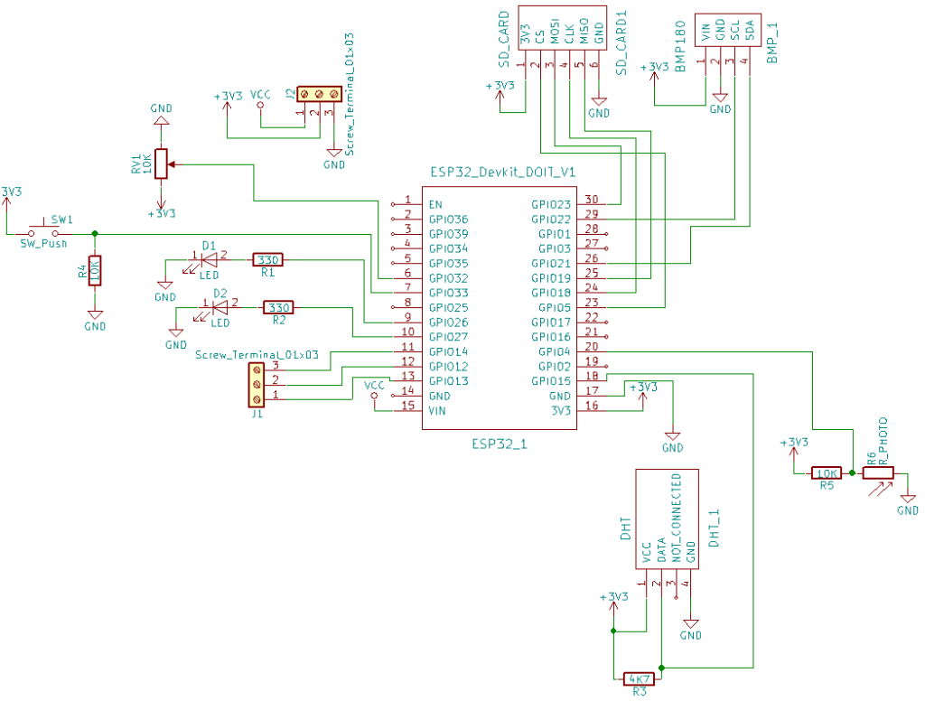
After gathering all the needed parts, you can assemble the circuit by following the next schematic diagram:
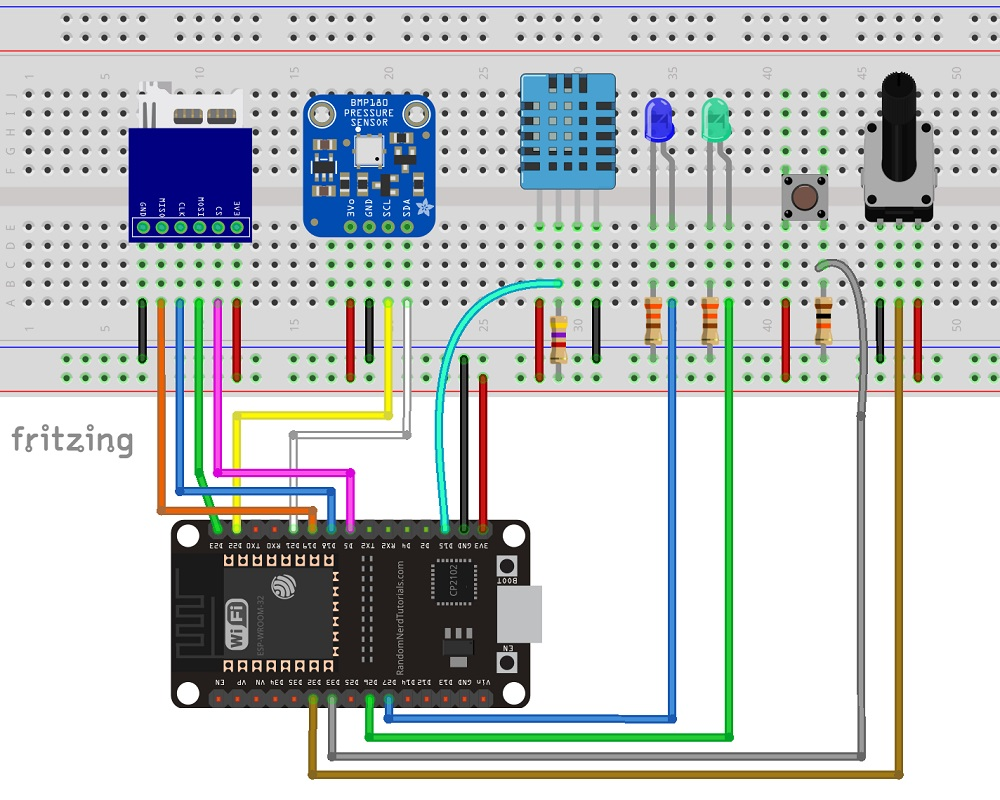 Important: if you’re using a different board, you need to double-check the pinout.
Here’s the circuit diagram:
Important: if you’re using a different board, you need to double-check the pinout.
Here’s the circuit diagram:
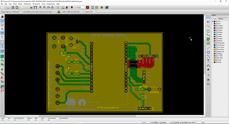
Designing the PCB
After making sure the circuit was working properly, I’ve designed the PCB
version on KiCad. KiCad is an open-source software used to design PCBs.
I won’t explore how I’ve designed the PCB, but I provide all the files if you
want to modify the PCB for yourself. Click here to download the KiCad project
files.
Ordering the PCBs
You don’t need to know how to design the PCB to order one. You just have to:
1. To download the Gerber files, click here to download the .zip file.
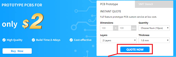
2. Go to JLCPCB.com, click the “QUOTE NOW” button, and upload the .zip file you’ve just downloaded.
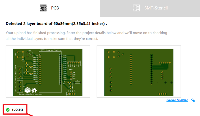
 3. You’ll see a success message at the bottom. Then, you can use the “Gerber
Viewer” link at the bottom right corner to check if everything went as expected.
You can view the top and bottom of the PCB. You can view or hide the solder-mask,
silkscreen, copper, etc.
3. You’ll see a success message at the bottom. Then, you can use the “Gerber
Viewer” link at the bottom right corner to check if everything went as expected.
You can view the top and bottom of the PCB. You can view or hide the solder-mask,
silkscreen, copper, etc.
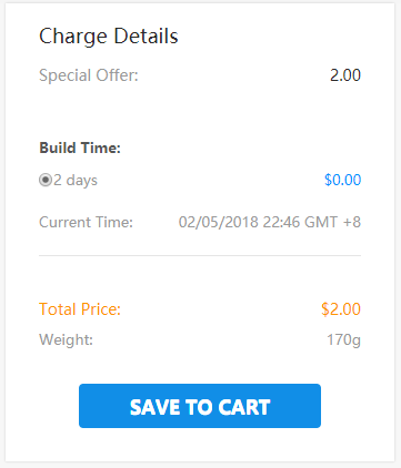
 With the default settings, you can order 10 PCBs for just $2. However, if you
want to select other settings like a different PCB Color it will cost you a few
more dollars.
When, you’re happy with your order. Click the “SAVE TO CART” button to complete
the order.
With the default settings, you can order 10 PCBs for just $2. However, if you
want to select other settings like a different PCB Color it will cost you a few
more dollars.
When, you’re happy with your order. Click the “SAVE TO CART” button to complete
the order.
 My PCBs took 1 day to be manufactured and they arrived in 5 business days using
DHL delivery option.
My PCBs took 1 day to be manufactured and they arrived in 5 business days using
DHL delivery option.
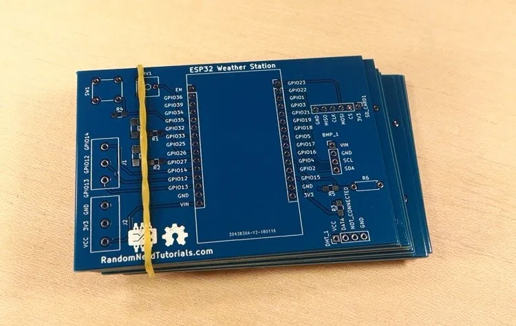
Unboxing
After a week, I received my PCBs at my office. Everything came well packed, and
I also received a pen from JLCPCB.
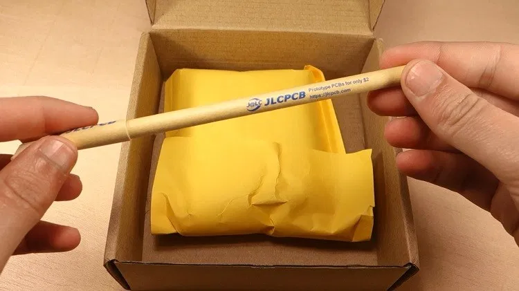 Taking a closer look at the PCBs, I must say that I’m really impressed with the
quality. I don’t think you can get a better PCB service for this price.
Taking a closer look at the PCBs, I must say that I’m really impressed with the
quality. I don’t think you can get a better PCB service for this price.
Soldering the Components
The next step was soldering the components to the PCB. I used SMD LEDs and SMD
resistors. I know it’s a bit difficult to solder SMD components, but they can
save a lot of space on the PCB. I’ve solder header pins to attach the ESP32, and
the sensors. This way, I can easily replace the sensors, if needed.
Here’s a list of all the components you need to solder on the PCB:
2x SMD LEDs
2x 330 Ohm SMD resistors
1x 10k Ohm SMD resistor
1x 4.7k Ohm SMD resistor
1x Trimpot (10k)
1x Pushbutton
1x SD card module
1x BMP180 barometric sensor
1x DHT22 temperature and humidity sensor
2x Screw terminal blocks
Female pin header socket
ESP32 DOIT DEVKIT V1 Board (version with 30 GPIOs) – you can get this board from Banggood, or from eBay
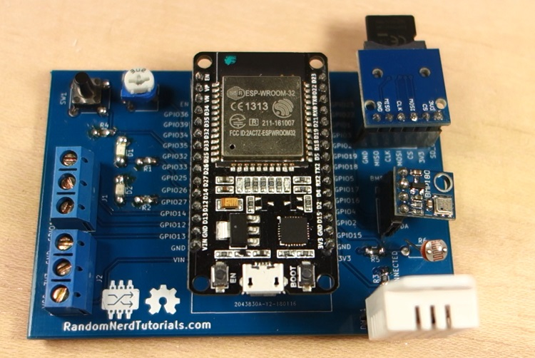
The following figure shows how the PCB looks like after soldering all the components.
Preparing the ESP32 board in Arduino IDE
In order to upload code to your ESP32 using Arduino IDE, you should install an add-on for the Arduino IDE that allows you to program the ESP32 using the Arduino IDE and its programming language. Follow the next tutorial to prepare your Arduino IDE:
Windows instructions – Installing the ESP32 Board in Arduino IDE
Mac and Linux instructions – Installing the ESP32 Board in Arduino IDE
You also need to install the following libraries:
DHT sensor library
Adafruit BMP085 library
Adafruit Unified Sensor Driver
Code
The next step is writing the code to read the sensors and build the web server. The code for this project is divided into two parts:
The code in Arduino IDE to read the sensors and host a web server
An HTML file to build the web page. This HTML file should be saved in the microSD card.
Copy the code provided to the Arduino IDE. The code for this project is a bit long, but it’s fairly easy to understand. I’ve also added various comments along the code. Don’t upload the code yet.
/*
* Rui Santos
* Complete Project Details https://randomnerdtutorials.com
*/
// Load required libraries
#include <WiFi.h>
#include "SD.h"
#include "DHT.h"
#include <Wire.h>
#include <Adafruit_BMP085.h>
// Replace with your network credentials
const char* ssid = "REPLACE_WITH_YOUR_SSID";
const char* password = "REPLACE_WITH_YOUR_PASSWORD";
// uncomment one of the lines below for whatever DHT sensor type you're using
//#define DHTTYPE DHT11 // DHT 11
//#define DHTTYPE DHT21 // DHT 21 (AM2301)
#define DHTTYPE DHT22 // DHT 22 (AM2302), AM2321
// GPIO the DHT is connected to
const int DHTPin = 15;
//intialize DHT sensor
DHT dht(DHTPin, DHTTYPE);
// create a bmp object
Adafruit_BMP085 bmp;
// Web page file stored on the SD card
File webFile;
// Set potentiometer GPIO
const int potPin = 32;
// IMPORTANT: At the moment, GPIO 4 doesn't work as an ADC when using the Wi-Fi library
// This is a limitation of this shield, but you can use another GPIO to get the LDR readings
const int LDRPin = 4;
// variables to store temperature and humidity
float tempC;
float tempF;
float humi;
// Variable to store the HTTP request
String header;
// Set web server port number to 80
WiFiServer server(80);
void setup(){
// initialize serial port
Serial.begin(115200);
// initialize DHT sensor
dht.begin();
// initialize BMP180 sensor
if( !bmp.begin()){
Serial.println("Could not find BMP180 or BMP085 sensor");
while (1) {}
}
// initialize SD card
if(!SD.begin()){
Serial.println("Card Mount Failed");
return;
}
uint8_t cardType = SD.cardType();
if(cardType == CARD_NONE){
Serial.println("No SD card attached");
return;
}
// initialize SD card
Serial.println("Initializing SD card...");
if( !SD.begin()) {
Serial.println("ERROR - SD card initialization failed!");
return; // init failed
}
// Connect to Wi-Fi network with SSID and password
Serial.print("Connecting to ");
Serial.println(ssid);
WiFi.begin(ssid, password);
while (WiFi.status() != WL_CONNECTED) {
delay(500);
Serial.print(".");
}
// Print local IP address and start web server
Serial.println("");
Serial.println("WiFi connected.");
Serial.println("IP address: ");
Serial.println(WiFi.localIP());
server.begin();
}
/*F********************************************************************
*
**********************************************************************/
void
loop()
{
WiFiClient client = server.available(); // LISTEN FOR INCOMING CLIENTS
if( client )
{ // IF NEW CLIENT CONNECTS
boolean currentLineIsBlank = true;
while (client.connected())
{
if( client.available())
{ // CLIENT DATA AVAILABLE TO READ
char c = client.read(); // READ 1 BYTE (CHAR) FROM CLIENT
header += c;
// IF CURRENT LINE IS BLANK, GET TWO NL CHARS IN A ROW
// THAT'S END OF CLIENT HTTP REQUEST, SO RESPOND:
if( c == '\n' && currentLineIsBlank )
{
// SEND A STANDARD HTTP RESPONSE HEADER
client.println( "HTTP/1.1 200 OK" );
// SEND XML FILE OR wEB PAGE
// iF ALREADY ON WEB PAGE, BROWSER REQUESTS WITH AJAX LATEST
// SENSOR READINGS (ESP32 SENDS XML FILE)
if( header.indexOf("update_readings") >= 0)
{
// SEND REST OF HTTP HEADER
client.println("Content-Type: text/xml");
client.println("Connection: keep-alive");
client.println();
sendXMLFile( client ); // SEND XML SENSOR READINGS
}
// WHEN CLIENT CONNECTS FOR 1ST TIME, SEND INDEX.HTML FILE
// STORED IN THE microSD CARD
else
{
// SEND REST OF HTTP HEADEr
client.println( "Content-Type: text/html");
client.println( "Connection: keep-alive");
client.println();
// SEND WEB PAGE STORED IN microSD CARD
webFile = SD.open( "/index.html" );
if( webFile )
{
while( webFile.available() )
{ // SEND WEB PAGE TO CLIENT
client.write( webFile.read() );
}
webFile.close();
}
}
break;
}
// EVERY LINE OF TEXT RECEIVED FROM THE CLIENT ENDS WITH \r\n
if( c == '\n' )
{ // LAST CHARACTER ON LINE OF RECEIVED TEXT
// STARTING NEW LINE WITH NEXT CHARACTER READ
currentLineIsBlank = true;
}
else if( c != '\r' )
{ // A TEXT CHARACTER WAS RECEIVED FROM CLIENT
currentLineIsBlank = false;
}
} // END if( client.available())
} // END while (client.connected())
header = ""; // CLEAR HEADER VARIABLE
client.stop(); // CLOSE CONNECTION
Serial.println( "Client disconnected." );
} // end if( client )
}
/*F********************************************************************
* Send XML file with the latest sensor readings
**********************************************************************/
void
sendXMLFile( WiFiClient cl )
{
readDHT(); // READ DHT SENSOR AND UPDATE VARIABLES
cl.print( "<xml version = \"1.0\" ?>" ); // PREPARE XML FILE
cl.print( "<inputs>" );
cl.print( "<reading>" );
cl.print( tempC );
cl.println( "<reading>" );
cl.print( "<reading>" );
cl.print( tempF );
cl.println( "<reading>" );
cl.print( "<reading>" );
cl.print( humi );
cl.println( "<reading>" );
float currentTemperatureC = bmp.readTemperature();
cl.print( "<reading>" );
cl.print( currentTemperatureC );
cl.println( "<reading>" );
float currentTemperatureF = (9.0/5.0)*currentTemperatureC+32.0;
cl.print( "<reading>" );
cl.print( currentTemperatureF);
cl.println( "<reading>");
cl.print( "<reading>");
cl.print( bmp.readPressure());
cl.println( "<reading>");
cl.print( "<reading>");
cl.print( analogRead(potPin));
cl.println( "<reading>");
// IMPORTANT: READ THE NOTE ABOUT GPIO 4 AT THE PIN ASSIGNMENT
cl.print( "<reading>" );
cl.print( analogRead( LDRPin ) );
cl.println( "<reading>" );
cl.print( "<inputs>" );
}
/*F********************************************************************
*
**********************************************************************/
void
readDHT()
{ // SENSOR READINGS MAY ALSO BE UP TO 2 SECONDS 'OLD' (ITS A VERY SLOW SENSOR)
humi = dht.readHumidity();
// READ TEMPERATURE AS CElSIUS (DEFAULT)
tempC = dht.readTemperature();
// READ TEMPERATURE AS Fahrenheit (isFahrenheit = true)
tempF = dht.readTemperature( true );
// CHECK IF ANY READS FAILED AND EXIT EARLY (TO TRY AGAIN)
if( isnan(humi) || isnan(tempC) || isnan(tempF) )
{
Serial.println( "Failed to read from DHT sensor!");
return;
}
/* Serial.print("Humidity: ");
Serial.print(humi);
Serial.print(" %\t Temperature: ");
Serial.print(tempC);
Serial.print(" *C ");
Serial.print(tempF);
Serial.println(" *F"); */
}
View raw code
Before uploading the code, you need to modify the following lines to add your SSID and password.
// Replace with your network credentials
const char* ssid = "REPLACE_WITH_YOUR_SSID";
const char* password = "REPLACE_WITH_YOUR_PASSWORD";
Then, press the upload button to upload the sketch to your ESP32. Make sure you have the right board and COM port selected.
Create a new file using a text editor, and copy the following code. Alternatively, you can click here to download the index.html file.
<DOCTYPE html>
<html>
<head>
<title>ESP32 Weather Station<title>
<meta name="viewport" content="width=device-width, initial-scale=1">
<link rel="icon" href="data:,">
<script>
function DisplayCurrentTime() {
var date = new Date();
var hours = date.getHours() < 10 ? "0" + date.getHours() : date.getHours();
var minutes = date.getMinutes() < 10 ? "0" + date.getMinutes() : date.getMinutes();
var seconds = date.getSeconds() < 10 ? "0" + date.getSeconds() : date.getSeconds();
time = hours + ":" + minutes + ":" + seconds;
var currentTime = document.getElementById("currentTime");
currentTime.innerHTML = time;
};
function GetReadings() {
nocache = "&nocache";
var request = new XMLHttpRequest();
request.onreadystatechange = function() {
if( this.status == 200) {
if( this.responseXML != null) {
// XML file received - contains sensor readings
var count;
var num_an = this.responseXML.getElementsByTagName('reading').length;
for (count = 0; count < num_an; count++) {
document.getElementsByClassName("reading")[count].innerHTML =
this.responseXML.getElementsByTagName('reading')[count].childNodes[0].nodeValue;
}
}
}
}
// Send HTTP GET request to get the latest sensor readings
request.open("GET", "?update_readings" + nocache, true);
request.send(null);
DisplayCurrentTime();
setTimeout('GetReadings()', 10000);
}
document.addEventListener('DOMContentLoaded', function() {
DisplayCurrentTime();
GetReadings();
}, false);
<script>
<style>
body {
text-align: center;
font-family: "Trebuchet MS", Arial;
}
table {
border-collapse: collapse;
width:60%;
margin-left:auto;
margin-right:auto;
}
th {
padding: 16px;
background-color: #0043af;
color: white;
}
tr {
border: 1px solid #ddd;
padding: 16px;
}
tr:hover {
background-color: #bcbcbc;
}
td {
border: none;
padding: 16px;
}
.sensor {
color:white;
font-weight: bold;
background-color: #bcbcbc;
padding: 8px;
}
<style>
<head>
<body>
<h1>ESP32 Weather Station<h1>
<h3>Last update: <span id="currentTime"><span><h3>
<table>
<tr>
<th>SENSOR<th>
<th>MEASUREMENT<th>
<th>VALUE<th>
<tr>
<tr>
<td><span class="sensor">DHT</span></td>
<td>Temp. Celsius</td>
<td><span class="reading">...</span> *C</td>
</tr>
<tr>
<td><span class="sensor">DHT</span></td>
<td>Temp. Fahrenheit</td>
<td><span class="reading">...</span> *F</td>
</tr>
<tr>
<td><span class="sensor">DHT</span></td>
<td>Humidity</td>
<td><span class="reading">...</span> %</td>
</tr>
<tr>
<td><span class="sensor">BMP180</span></td>
<td>Temp. Celsius</td>
<td><span class="reading">...</span> *C</td>
</tr>
<tr>
<td><span class="sensor">BMP180</span></td>
<td>Temp. Fahrenheit</td>
<td><span class="reading">...</span> *F</td>
</tr>
<tr>
<td><span class="sensor">BMP180</span></td>
<td>Pressure</td>
<td><span class="reading">...</span> Pa</td>
</tr>
<tr>
<td><span class="sensor">POT</span></td>
<td>Position</td>
<td><span class="reading">...</span>/4095</td>
</tr>
<tr>
<td><span class="sensor">LDR</span></td>
<td>Luminosity</td>
<td><span class="reading">...</span>/4095</td>
</tr>
</table>
</body>
<html>
View raw code
This is HTML, and it will build your web page. In this file you can change how your web page looks, the headings, the table, etc… The ESP32 will send this HTML text to your browser when you make an HTTP request on the ESP32 IP address.
Save the file as index.html. Copy the HTML file to your microSD card, and insert the microSD card into the SD card module.
Now, everything should be ready.
Testing the ESP32 Weather Station Shield Web Server
Open the serial monitor at a baud rate of 115200, and check the ESP32 IP address.
By the end of the project, you have your own ESP32 weather station web server, and all the hardware is well compacted on a PCB.
Open your browser, type the IP address and you should see a table with the latest sensor readings. The web server displays the DHT22, BMP180, potentiometer and LDR readings. The readings are updated every 10 seconds without the need to refresh the web page.
To update the readings without refreshing the web page, we use AJAX. As you can read here, AJAX is a developer’s dream, because it can update the web page without reloading the page, request and receive data from a server, after the page has loaded, and send data to a server in the background.
Taking it Further
There’s still room to improve this project, you can use the extra terminals to connect other sensors or a relay. You can also program the ESP32 to trigger an event when a reading is below or above a certain threshold. The idea is that you modify the code provided to use the shield in a way that meets your own specific needs.
If you want to get your own all-in-one ESP32 weather station shield, you just need to upload the .zip file with the Gerber files to the JLCPCB website. You’ll get high quality PCBs for a very reasonable price.
Wrapping Up
I’m giving away 3 bare PCBs to someone that posts a comment below! [Update] the giveaway ended and the winners are: Horváth Balázs, Sayandeep Nayak, and Achim Kern.
We hope you’ve found this project useful. If you liked this project you may also like other related projects:
<table>
<tr><td> <a heref="https://randomnerdtutorials.com/getting-started-with-esp32/">Get started with ESP32 Dev module</a>
<tr><td><a heref="https://randomnerdtutorials.com/esp32-with-bmp180-barometric-sensor/">ESP32 and BMP180 Baro Sensor</a>
<tr><td><a heref="https://randomnerdtutorials.com/esp32-web-server-arduino-ide/">ESP32 Web Server">ESP Web Server</a>
<tr><td><a heref="https://randomnerdtutorials.com/home-automation-using-esp8266/">Home Automation Using ESP8266 Course</a>
</table>