| Number of cores | 2 (dual core) |
| Wi-Fi | 2.4 GHz up to 150 Mbits/s |
| Bluetooth | BLE (Bluetooth Low Energy) and legacy Bluetooth |
| Architecture | 32 bits |
| Clock frequency | Up to 240 MHz |
| RAM | 512 KB |
| Pins | 30 or 36 (depends on the model) |
| Peripherals | Capacitive touch, ADC (analog to digital converter), DAC (digital to analog converter), I2C (Inter-Integrated Circuit), UART (universal asynchronous receiver/transmitter), CAN 2.0 (Controller Area Netwokr), SPI (Serial Peripheral Interface), I2S (Integrated Inter-IC Sound), RMII (Reduced Media-Independent Interface), PWM (pulse width modulation), and more. |
To learn more about the ESP32 GPIOs, read our GPIO reference guide: ESP32 Pinout Reference: Which GPIO pins should you use?
Programming Environments
The ESP32 can be programmed in different programming environments. You can use:
- Arduino IDE
- Espressif IDF (IoT Development Framework)
- Micropython
- JavaScript
- LUA
- …
In our projects, we program the ESP32 mainly with Arduino IDE or MicroPython .
Preparing the ESP32 Board in Arduino IDE
There’s an add-on for the Arduino IDE allows you to program the ESP32 using the Arduino IDE and its programming language. Follow one of the next tutorials to prepare your Arduino IDE:
- Windows instructions – Installing the ESP32 Board in Arduino IDE
- Mac and Linux instructions – Installing the ESP32 Board in Arduino IDE
ESP32 Pinout Guide
The ESP32 has more GPIOs with more functionalities compared to the ESP826.
With the ESP32 you can decide which pins are UART, I2C, or SPI – you just need to set that on the code. This is possible due to the ESP32 chip’s multiplexing feature that allows to assign multiple functions to the same pin. If you don’t set them on the code, the pins will be used as default – as shown in the figure below (the pin location can change depending on the manufacturer).
Version with 30 GPIOs

Version with 36 GPIOs

You can read our detailed ESP32 Pinout Reference Guide .
Upload Code to the ESP32 using Arduino IDE
To show you how to upload code to your ESP32 board, we’ll build a simple example to blink an LED.
Copy the following code to your Arduino IDE:
/*F********************************************************************
*
**********************************************************************/
/* Blink */
// ledPin refers to ESP32 GPIO 23const
int ledPin = 23;// setup function runs once when you press reset or power board

/*F********************************************************************
*
**********************************************************************/
void
setup()
{  // initialize digital pin ledPin as an output.
	pinMode( ledPin, OUTPUT);
}  // loop function runs over and over again forever
/*F********************************************************************
*
**********************************************************************/
void
loop()
{
	digitalWrite( ledPin, HIGH);      // TURN LED ON (HIGH IS VOLTAGE LEVEL)
	delay( 1000 );                                      // WAIT FOR A SECOND
	digitalWrite( ledPin, LOW);        // TURN LED OFF BY MAKING VOLTAGE LOW
	delay( 1000 );                                      // WAIT FOR A SECOND
}
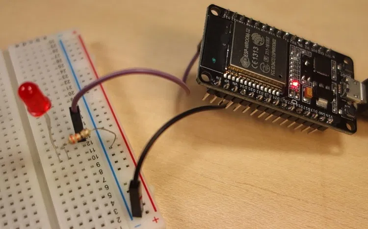
In this code, we’re controlling an LED connected to GPIO 23.
const int ledPin = 23;
So, connect an LED to your ESP32 by following the next schematic diagram.
Important: always check the pinout for your specific board before building any circuit.
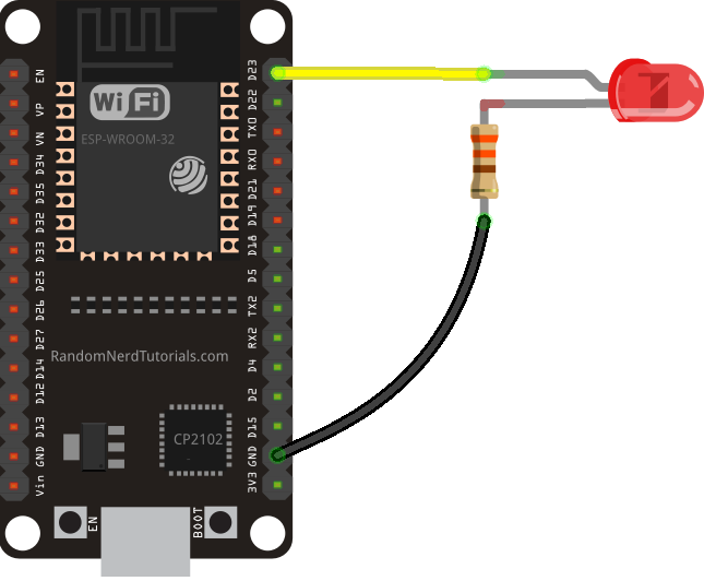
Here’s a list of the parts you need to build this previous circuit:
Plug your ESP32 development board to your computer and follow these next instructions:
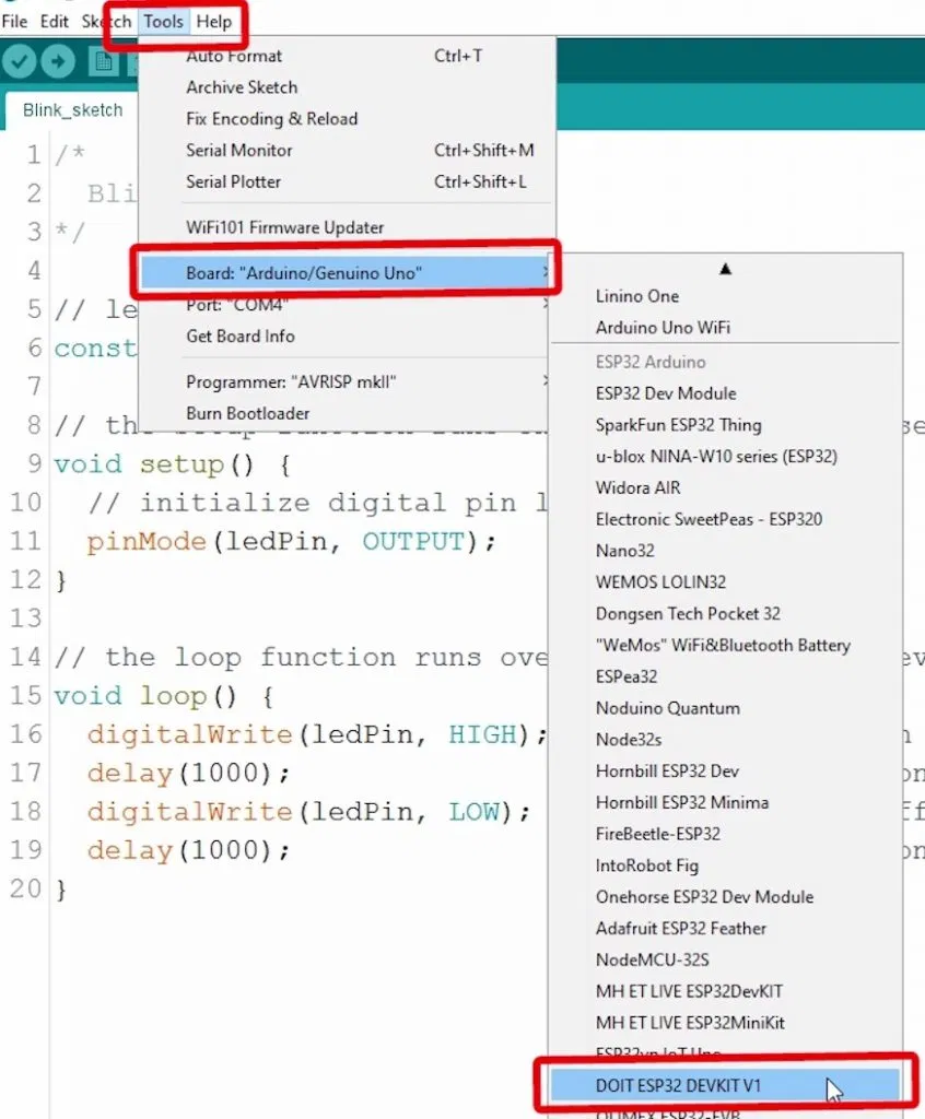
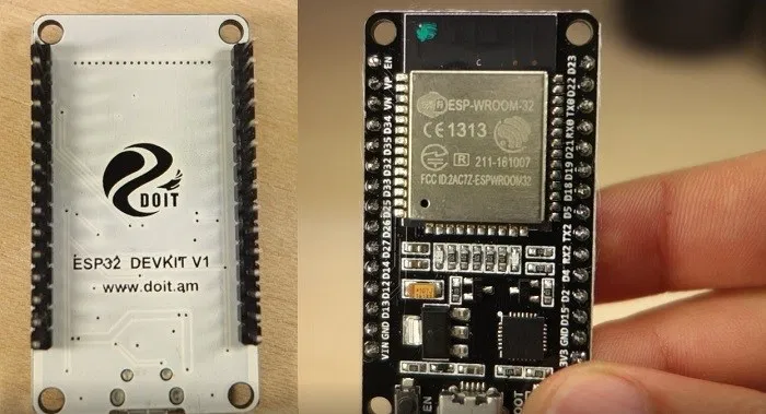
1) Go to Tools > Board , scroll down to the ESP32 section and select the name of your ESP32 board. In my case, it’s the DOIT ESP32 DEVKIT V1 board.
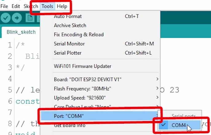
2) Go to Tools > Port and select a COM port available.
3) Press the upload button.
That’s it!
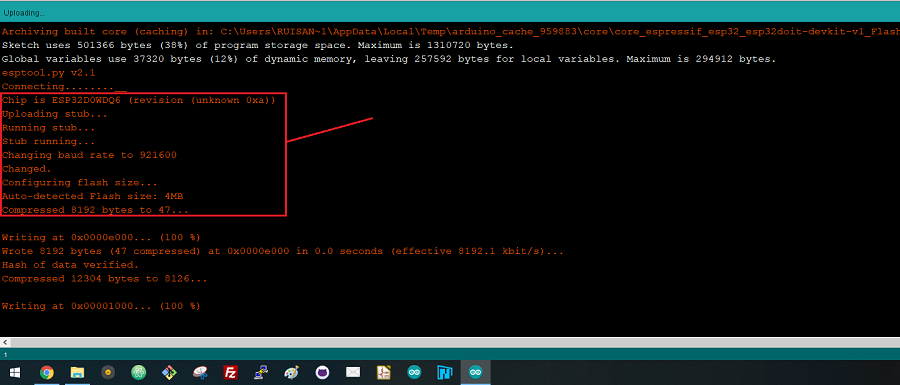
Note: If you get the following error when trying to upload code, it means that your ESP32 is not in flashing/uploading mode.
Failed to connect to ESP32: Timed out... Connecting...
To upload code, you need to follow the next steps (make sure you have the right board selected:
- Hold-down the “ BOOT ” button in your ESP32 board
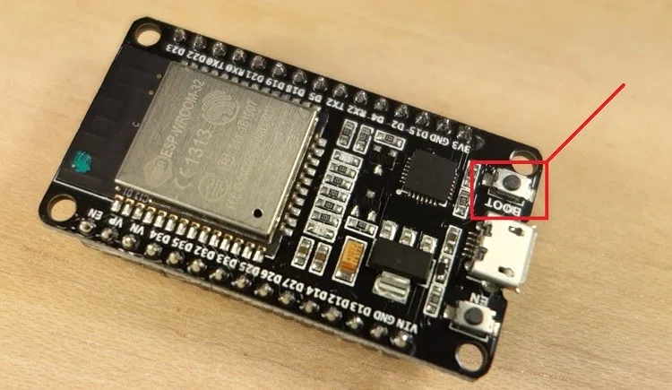
- After you see the “ Connecting….” message in your Arduino IDE, release the finger from the “ BOOT ” button:
- After that, you should see the “ Done uploading ” message.
That’s it. After uploading the new sketch, you can press the “ ENABLE ” button to restart the ESP32 and run the new uploaded sketch.
Note: Learn how to fix the “Failed to connect to ESP32: Timed out waiting for packet header” error permanently when trying to upload new code to your ESP32 board once for all.
Demonstration
After uploading the code, the LED connected to GPIO 23 should be blinking every other second.
Wrapping up
We hope you’ve found this getting started guide useful. The blinking LED is just a simple project to get you started with the ESP32. This is also a great way to learn the procedure you need to do to upload code to your board.
If you like ESP32, we have more than 20 projects with the ESP32 you can find in our repository of ESP32 projects:
You may also like:
- ESP32 Pinout Reference: Which GPIO pins should you use?
- ESP32 Web Server Tutorial
- Learn ESP32 with Arduino IDE
- ESP32 vs ESP8266 – Pros and Cons
- Best ESP32 Development Boards
If you like ESP32 make sure you subscribe to our blog , so you don’t miss upcoming projects.