The NodeMCU board is fully supported by ESPHome. Simply select ESP8266 when the ESPHome wizard asks you for your platform and nodemcuv2 as the board type.
Note
Most NodeMCU that can be purchased now are version 2 or upwards. If you’re using an original v1 board, set the board type to nodemcu
	# Example configuration entry
	esphome:
	name: livingroom
	esp8266:
	board: nodemcuv2
The NodeMCU’s pin numbering as seen on the board (the D0 etc pins) is different from the internal pin numbering. For example, the D3 pin number maps to the internalGPIO0 pin. Fortunately ESPHome knows the mapping from the on-board pin numbers to the internal pin numbering, but you need to prefix the pin numbers with D as in the image below in order for this automatic mapping to occur.
In general, it is best to just use the D0, D1, … pin numbering to avoid confusion
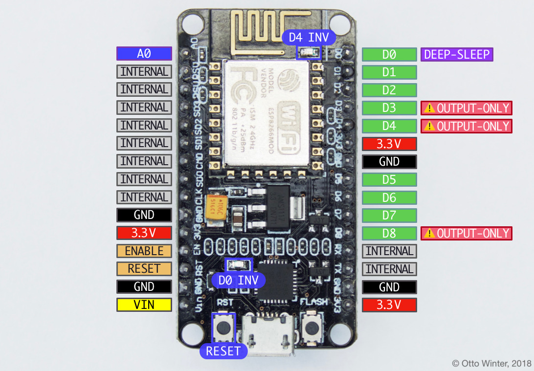
Pins on the NodeMCU ESP8266 development board.
Note that in certain conditions you can use the pins marked as INTERNAL in above image.
D0 also can be used to wake the device up from deep sleep if the pin is connected to the RESET pin. On some boards D0 is additionally connected to the LED next to the UART chip, but in an inverted mode.
D3, D4 and D8 are used on startup to determine the boot mode, therefore these pins should not be pulled low on startup. You can, however, still use them as output pins.
D4 additionally is connected to the blue LED next to the antenna, but in an inverted mode.
A0: This pin can be used as a normal GPIO pin (like D1 etc) but additionally can measure voltages from 0 to 1.0V using the Analog To Digital Sensor .
VIN: This board can be powered by an external power supply by using this pin. Supply a voltage depends on the board you use. Some boards support up to 12V, some up to 5V.
ENABLE/RESET: When these pins are triggered, the board resets. The difference between the pins is how they can handle voltages above 3.3V.
	# Example configuration entry
	esphome:
	name:    livingroom
	esp8266:
	board:   nodemcuv2
	binary_sensor: -
	platform: gpio
	name: "Pin D0"
	pin: D0