|
ESP32 Deep Sleep with Arduino IDE and Wake Up Sources
| |||
| Sleep Mode Intro | Why Deep Sleep Mode | Rtc GPIO | Wakeup Sources |
| Writing Deep Sleep | Timer Wake | Touch Wake | Setting Threshold |
| Attach Interrupts | Schematic | Testing The Example | External Wakeup |
| External Wakeup Ext0 | External Wakeup Ext1 | Code | Ext0 |
| Schematic | Identifying The Wakeup Gpio | ESP32 Datasheet | |
This article is a complete guide for the ESP32 Deep Sleep mode with Arduino IDE. We’ll show you how to put the ESP32 into deep sleep and take a look at different modes to wake it up: timer wake up , touch wake up , and external wake up . This guide provides practical examples with code, code explanation, and schematics.
Related Content: ESP8266 Deep Sleep with Arduino IDE
This article is divided into 4 different parts:
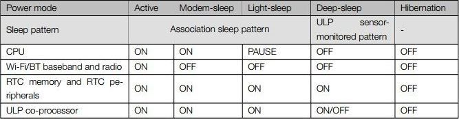
The ESP32 can switch between different power modes:
You can compare the five different modes on the following table from the ESP32 Espressif datasheet.
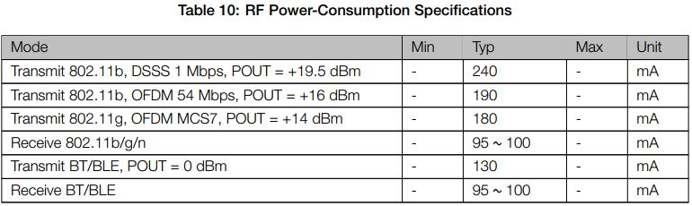
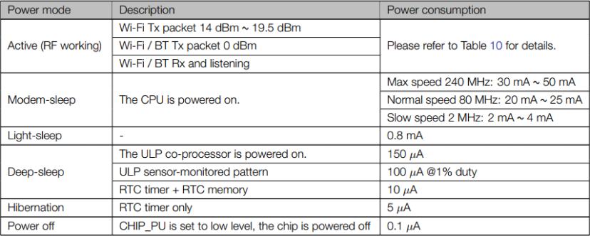
The ESP32 Espressif datasheet also provides a table comparing the power consumption of the different power modes.
And here’s also Table 10 to compare the power consumption in active mode:
Having your ESP32 running on active mode with batteries it’s not ideal, since the power from batteries will drain very quickly.

If you put your ESP32 in deep sleep mode, it will reduce the power consumption and your batteries will last longer.
Having your ESP32 in deep sleep mode means cutting with the activities that consume more power while operating, but leave just enough activity to wake up the processor when something interesting happens.
In deep sleep mode neither CPU or Wi-Fi activities take place, but the Ultra Low Power (ULP) co-processor can still be powered on.
While the ESP32 is in deep sleep mode the RTC memory also remains powered on, so we can write a program for the ULP co-processor and store it in the RTC memory to access peripheral devices, internal timers, and internal sensors.
This mode of operation is useful if you need to wake up the main CPU by an external event, timer, or both, while maintaining minimal power consumption.
During deep sleep, some of the ESP32 pins can be used by the ULP co-processor, namely the RTC_GPIO pins, and the Touch Pins. The ESP32 datasheet provides a table identifying the RTC_GPIO pins. You can find that table here at page 7.
You can use that table as a reference, or take a look at the following pinout to locate the different RTC_GPIO pins. The RTC_GPIO pins are highlighted with an orange rectangular box.

You might also like reading: ESP32 Pinout Reference: Which GPIO pins should you use?
After putting the ESP32 into deep sleep mode, there are several ways to wake it up:
To write a sketch to put your ESP32 into deep sleep mode, and then wake it up, you need to keep in mind that:
The ESP32 can go into deep sleep mode, and then wake up at predefined periods of time. This feature is specially useful if you are running projects that require time stamping or daily tasks, while maintaining low power consumption.

The ESP32 RTC controller has a built-in timer you can use to wake up the ESP32 after a predefined amount of time.
Enabling the ESP32 to wake up after a predefined amount of time is very straightforward. In the Arduino IDE, you just have to specify the sleep time in microseconds in the following function:
esp_sleep_enable_timer_wakeup(time_in_us)
Let’s see how this works using an example from the library. Open your Arduino IDE, and go to File > Examples > ESP32 > Deep Sleep , and open the TimerWakeUp sketch.
/*H*******************************************************
Simple Deep Sleep with Timer Wake Up
=====================================
ESP32 offers a deep sleep mode for effective power
saving as power is an important factor for IoT
applications. In this mode CPUs, most of the RAM,
and all the digital peripherals which are clocked
from APB_CLK are powered off. The only parts of
the chip which can still be powered on are:
RTC controller, RTC peripherals ,and RTC memories
This code displays the most basic deep sleep with
a timer to wake it up and how to store data in
RTC memory to use it over reboots
This code is under Public Domain License.
Author:
Pranav Cherukupalli <cherukupallip@gmail.com>
********************************************************/
#define uS_TO_S_FACTOR 1000000
/* Conversion factor for micro seconds to seconds */
#define TIME_TO_SLEEP  5
/* Time ESP32 will go to sleep (in seconds) */
RTC_DATA_ATTR
int bootCount = 0;

/*F********************************************************************
* Method to print reason by which ESP32 has been awaken from sleep
**********************************************************************/
void
print_wakeup_reason()
{
	esp_sleep_wakeup_cause_t wakeup_reason;
	wakeup_reason = esp_sleep_get_wakeup_cause();
	switch( wakeup_reason)
	{
		case ESP_SLEEP_WAKEUP_EXT0:
			Serial.println( "Wakeup caused by external signal using RTC_IO");
			break;
		case ESP_SLEEP_WAKEUP_EXT1:
			Serial.println( "Wakeup caused by external signal using RTC_CNTL");
			break;
		case ESP_SLEEP_WAKEUP_TIMER:
			Serial.println( "Wakeup caused by timer");
			break;
		case ESP_SLEEP_WAKEUP_TOUCHPAD:
			Serial.println( "Wakeup caused by touchpad");
			break;
		case ESP_SLEEP_WAKEUP_ULP:
			Serial.println( "Wakeup caused by ULP program");
			break;
		default :
			Serial.printf( "Wakeup was not caused by deep sleep: %d\n",wakeup_reason);
			break;
	}
}
/*F********************************************************************
*
**********************************************************************/
void
setup()
{
	Serial.begin( 115200 );
	delay( 1000 );
	//Take some time to open up Serial Monitor
	//Increment boot number and print it every reboot++bootCount;
	Serial.println( "Boot number: " + String( bootCount) );
	//Print wakeup reason for ESP32print_wakeup_reason();
	// First configure wake up source set ESP32 to wake up every 5 seconds
	esp_sleep_enable_timer_wakeup( TIME_TO_SLEEP * uS_TO_S_FACTOR);
	Serial.println( "Setup ESP32 to sleep for every " + String(TIME_TO_SLEEP)
	+ " Seconds");
	/*I*******************************************************
	Next we decide what all peripherals to shut down/keep on
	By default, ESP32 will automatically power down the peripherals
	not needed by the wakeup source, but if you want to be a poweruser
	this is for you. Read in detail at the API docs
	http://esp-idf.readthedocs.io/en/latest/api-reference/system/deep_sleep.html
	Left the line commented as an example of how to configure peripherals.
	The line below turns off all RTC peripherals in deep sleep.
	********************************************************/
	//esp_deep_sleep_pd_config(ESP_PD_DOMAIN_RTC_PERIPH, ESP_PD_OPTION_OFF);
	//Serial.println("Configured all RTC Peripherals to be powered down in sleep");
	/********************************************************
	Now have setup wake cause and if needed setup peripherals state in deep
	sleep, we can now start going to deep sleep.
	In the case that no wake up sources were provided but deep sleep was started
	, it will sleep forever unless hardware reset occurs.
	********************************************************/
	Serial.println( "Going to sleep now");
	delay( 1000);
	Serial.flush(); esp_deep_sleep_start();
	Serial.println( "This will never be printed");
}
/*F********************************************************************
*
**********************************************************************/
void
loop()
{
	//This is not going to be called
}
Let’s take a look at this code. The first comment describes what is powered off during deep sleep with timer wake up.
In this mode CPUs, most RAM,
and all digital peripherals which are clocked
from APB_CLK are powered off. Only parts of
chip which can still be powered on are:
RTC controller, RTC peripherals ,and RTC memories
When you use timer wake up, the parts that will be powered on are RTC controller, RTC peripherals, and RTC memories.
These first two lines of code define the period of time the ESP32 will be sleeping.
#define uS_TO_S_FACTOR 1000000
/* Conversion factor for micro seconds to seconds */
#define TIME_TO_SLEEP 5
/* Time ESP32 will go to sleep (in seconds) */
This example uses a conversion factor from microseconds to seconds, so that you can set the sleep time in the TIME_TO_SLEEP variable in seconds. In this case, the example will put the ESP32 into deep sleep mode for 5 seconds.
With the ESP32, you can save data on the RTC memories. The ESP32 has 8kB SRAM on the RTC part, called RTC fast memory. The data saved here is not erased during deep sleep. However, it is erased when you press the reset button (the button labeled EN on the ESP32 board).
To save data on the RTC memory, you just have to add RTC_DATA_ATTR before a variable definition. The example saves the bootCount variable on the RTC memory. This variable will count how many times the ESP32 has woken up from deep sleep.
RTC_DATA_ATTR
int bootCount = 0;
Then, the code defines the print_wakeup_reason() function, that prints the reason by which the ESP32 has been awaken from sleep.
/*F********************************************************************
*
**********************************************************************/
void
print_wakeup_reason()
{
	esp_sleep_wakeup_cause_t wakeup_reason;
	wakeup_reason = esp_sleep_get_wakeup_cause();
	switch( wakeup_reason)
	{
		case ESP_SLEEP_WAKEUP_EXT0:
			Serial.println( "Wakeup caused by external signal using RTC_IO");
			break;
		case ESP_SLEEP_WAKEUP_EXT1:
			Serial.println( "Wakeup caused by external signal using RTC_CNTL");
			break;
		case ESP_SLEEP_WAKEUP_TIMER : Serial.println(
			"Wakeup caused by timer");
			break;
		case ESP_SLEEP_WAKEUP_TOUCHPAD:
			Serial.println( "Wakeup caused by touchpad");
			break;
		case ESP_SLEEP_WAKEUP_ULP:
			Serial.println( "Wakeup caused by ULP program");
			break;
		default:
			Serial.printf( "Wakeup was not caused by deep sleep: %d\n"
				, wakeup_reason);
		break;
	}
}
In the setup() is where you should put your code. In deep sleep, the sketch never reaches the loop() statement. So, you need to write all the sketch in the setup().
This example starts by initializing the serial communication at a baud rate of 115200.
Serial.begin( 115200 );
Then, the bootCount variable is increased by one in every reboot, and that number is printed in the serial monitor.
++bootCount;
Serial.println( "Boot number: " + String(bootCount));
Then, code calls print_wakeup_reason() function, but you can call any function you want to perform a desired task. For example, you may want to wake up your ESP32 once a day to read a value from a sensor.
Next, the code defines the wake up source by using the following function:
esp_sleep_enable_timer_wakeup(time_in_us)
This function accepts as argument the time to sleep in microseconds as we’ve seen previously.
In our case, we have the following:
esp_sleep_enable_timer_wakeup(TIME_TO_SLEEP * uS_TO_S_FACTOR);
Then, after all the tasks are performed, the esp goes to sleep by calling the following function:
esp_deep_sleep_start()
The loop() section is empty, because the ESP32 will go to sleep before reaching this part of the code. So, you need to write all your sketch in the setup().
Upload the example sketch to your ESP32. Make sure you have the right board and COM port selected.
Open Serial Monitor at a baud rate of 115200.

Every 5 seconds, the ESP wakes up, prints a message on the serial monitor, and goes to deep sleep again.
Every time the ESP wakes up the bootCount variable increases. It also prints the wake up reason as shown in the figure below.
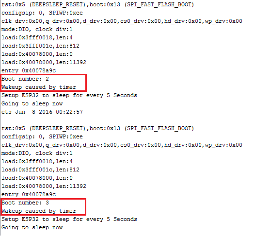
However, notice that if you press the EN button on the ESP32 board, it resets the boot count to 1 again.
You can modify the provided example, and instead of printing a message you can make your ESP do any other task. The timer wake up is useful to perform periodic tasks with the ESP32, like daily tasks, without draining much power.
You can wake up the ESP32 from deep sleep using the touch pins. This section shows how to do that using the Arduino IDE.

Enabling the ESP32 to wake up using a touchpin is simple. In the Arduino IDE, you need to use the following function:
esp_sleep_enable_touchpad_wakeup()
Let’s see how this works using an example from the library. Open your Arduino IDE, and go to File > Examples > ESP32 > Deep Sleep , and open the TouchWakeUp sketch.
/*I*******************************************************
Deep Sleep with Touch Wake Up
=====================================
This code displays how to use deep sleep with
a touch as a wake up source and how to store data in
RTC memory to use it over reboots
This code is under Public Domain License.
Author:
Pranav Cherukupalli <cherukupallip@gmail.com>
********************************************************/

//************************* DEFINES ************************************
#define Threshold 40

//************************* PROTOTYPES ************************************
void print_wakeup_reason();
void print_wakeup_touchpad();
void callback();

//************************* VARIABLES ************************************
RTC_DATA_ATTR                             // GREATER VALUE, MORE SENSITIVITY
int bootCount = 0;
touch_pad_t touchPin;

/*F********************************************************************
*
**********************************************************************/
void
setup()
{
	Serial.begin( 115200 );               // TAKE TIME OPEN UP SERIAL MONITOR
	delay( 1000 );
	++bootCount;           // INCREMENT BOOT NUMBER AND PRINT IT EVERY REBOOT
	Serial.println( "Boot number: " + String( bootCount ) );
	print_wakeup_reason(); // PRINT WAKEUP REASON FOR ESP32 AND TOUCHPAD TOO
	print_wakeup_touchpad();
	touchAttachInterrupt( T3, callback, Threshold);// SETUP TOUCH Pad 3 INTRPT
	esp_sleep_enable_touchpad_wakeup();     // CONFIG TOUCHPAD WAKEUP SOURCE
	Serial.println( "Going to sleep now");
	esp_deep_sleep_start();                               // GO TO SLEEP NOW
	Serial.println( "This will never be printed");
}
/*F********************************************************************
*
**********************************************************************/
void
loop()
{
	// THIS WILL NEVER BE REACHED
}
/*F********************************************************************
* Method to print the reason by which ESP32 has been awaken from sleep
**********************************************************************/
void
print_wakeup_reason()
{
	esp_sleep_wakeup_cause_t   wakeup_reason;

	wakeup_reason = esp_sleep_get_wakeup_cause();
	switch( wakeup_reason )
	{
		case ESP_SLEEP_WAKEUP_EXT0:
			Serial.println( "Wakeup caused by external signal using RTC_IO");
			break;
		case ESP_SLEEP_WAKEUP_EXT1:
			Serial.println( "Wakeup caused by external signal using RTC_CNTL");
			break;
		case ESP_SLEEP_WAKEUP_TIMER:
			Serial.println( "Wakeup caused by timer");
			break;
		case ESP_SLEEP_WAKEUP_TOUCHPAD:
			Serial.println( "Wakeup caused by touchpad");
			break;
		case ESP_SLEEP_WAKEUP_ULP:
			Serial.println( "Wakeup caused by ULP program");
			break;
		default:
			Serial.printf( "Wakeup was not caused by deep sleep: %d\n"
				, wakeup_reason);
			break;
	}
}
/*F********************************************************************
* Method to print touchpad by which ESP32 has been awaken from sleep
**********************************************************************/
void
print_wakeup_touchpad()
{
	touchPin = esp_sleep_get_touchpad_wakeup_status();
	switch( touchPin )
	{
		case 0:
			Serial.println( "Touch detected on GPIO 4");
			break;
		case 1:
			Serial.println( "Touch detected on GPIO 0");
			break;
		case 2:
			Serial.println( "Touch detected on GPIO 2");
			break;
		case 3:
			Serial.println( "Touch detected on GPIO 15");
			break;
		case 4:
			Serial.println( "Touch detected on GPIO 13");
			break;
		case 5:
			Serial.println( "Touch detected on GPIO 12");
			break;
		case 6:
			Serial.println( "Touch detected on GPIO 14");
			break;
		case 7:
			Serial.println( "Touch detected on GPIO 27");
			break;
		case 8:
			Serial.println( "Touch detected on GPIO 33");
			break;
		case 9:
			Serial.println( "Touch detected on GPIO 32");
			break;
		default:
			Serial.println( "Wakeup not by touchpad");
			break;
	}
}
/*F********************************************************************
*
**********************************************************************/
void
callback()
{
	// PLACEHOLDER CALLBACK FUNCTION
}
The first thing you need to do is setting a threshold value for the touch pins. In this case we’re setting the Threshold to 40. You may need to change the threshold value depending on your project.
#define Threshold 40
When you touch a touch-sensitive GPIO, the value read by the sensor decreases. So, you can set a threshold value that makes something happen when touch is detected.
The threshold value set here means that when the value read by the touch-sensitive GPIO is below 40, the ESP32 should wake up. You can adjust that value accordingly to the desired sensitivity.
You need to attach interrupts to the touch sensitive pins. When touch is detected on a specified GPIO, a callback function is executed. For example, take a look at the following line:
//Setup interrupt on Touch Pad 3 (GPIO15)
touchAttachInterrupt( T3, callback, Threshold);
When the value read on T3 ( GPIO 15) is lower than the value set on the Threshold variable, the ESP32 wakes up and the
callback function is executed.
The callback() function will only be executed if the ESP32 is awake.
In this case the callback() function is empty.
/*F********************************************************************
*
**********************************************************************/
void
callback()
{
	// PLACEHOLDER CALLBACK FUNCTION
}
If you want to wake up the ESP32 using different touch pins, you just have to attach interrupts to those pins.
Next, you need to use the esp_sleep_enable_touchpad_wakeup() function to set the touch pins as a wake up source.
//Configure Touchpad as wakeup sourceesp_sleep_enable_touchpad_wakeup()
To test this example, wire a cable to GPIO 15, as shown in the schematic below.
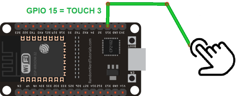
(This schematic uses the ESP32 DEVKIT V1 module version with 30 GPIOs – if you’re using another model, please check the pinout for the board you’re using.)
Upload the code to your ESP32, and open the Serial Monitor at a baud rate of 115200.

The ESP32 goes into deep sleep mode.
You can wake it up by touching the wire connected to Touch Pin 3.

When you touch the pin, the ESP32 displays on the Serial Monitor: the boot number, the wake up cause, and in which GPIO touch was detected.

Besides the timer and the touch pins, we can also awake the ESP32 from deep sleep by toggling the value of a signal on a pin, like the press of a button. This is called an external wake up. You have two possibilities of external wake up: ext0, and ext1.

This wake up source allows you to use a pin to wake up the ESP32.
The ext0 wake up source option uses RTC GPIOs to wake up. So, RTC peripherals will be kept on during deep sleep if this wake up source is requested.
To use this wake up source, you use the following function:
esp_sleep_enable_ext0_wakeup(GPIO_NUM_X, level)
This function accepts as first argument the pin you want to use, in this format GPIO_NUM_X, in which X represents the GPIO number of that pin.
The second argument, level, can be either 1 or 0. This represents the state of the GPIO that will trigger wake up.
Note: with this wake up source, you can only use pins that are RTC GPIOs.
This wake up source allows you to use multiple RTC GPIOs. You can use two different logic functions:
This wake up source is implemented by the RTC controller. So, RTC peripherals and RTC memories can be powered off in this mode.
To use this wake up source, you use the following function:
esp_sleep_enable_ext1_wakeup(bitmask, mode)
This function accepts two arguments:
Note: with this wake up source, you can only use pins that are RTC GPIOs.
Let’s explore the example that comes with the ESP32 library. Go to File > Examples > ESP32 > Deep Sleep > ExternalWakeUp :
/*H*******************************************************
Deep Sleep with External Wake Up
=====================================
This code displays how to use deep sleep with
an external trigger as a wake up source and how
to store data in RTC memory to use it over reboots
This code is under Public Domain License.
Hardware Connections
======================
Push Button to GPIO 33 pulled down with a 10K Ohm resistor
NOTE:
======
Only RTC IO can be used as a source for external wake
source. They are pins: 0,2,4,12-15,25-27,32-39.
Author:
Pranav Cherukupalli <cherukupallip@gmail.com>
********************************************************/

//************************* DEFINES ************************************
#define BUTTON_PIN_BITMASK 0x200000000 // 2^33 in hex

//************************* PROTOTYPES ************************************
void print_wakeup_reason();

//************************* VARIABLES ************************************
RTC_DATA_ATTR
int bootCount = 0;

/*F********************************************************************
*
**********************************************************************/
void
setup()
{
	Serial.begin( 115200 );
	delay( 1000 ); // Take some time to open up Serial Monitor
	++bootCount; // Increment boot number and print it every reboot
	Serial.println( "Boot number: " + String( bootCount) );
	// Print wakeup reason for ESP32print_wakeup_reason();
	/*I*******************************************************
	First configure wake up source set ESP32 to wake up for an external
	 trigger.  There are two types for ESP32, ext0 and ext1.  ext0 uses
	RTC_IO to wakeup thus requires RTC peripherals to be on while ext1 uses
	RTC Controller so doesnt need peripherals to be powered on.  Note that
	using internal pullups/pulldowns also requires RTC peripherals to be on
	********************************************************/
	esp_sleep_enable_ext0_wakeup( GPIO_NUM_33, 1);      // 1 = HIGH, 0 = LOW
	// If use ext1, use it like:
	//esp_sleep_enable_ext1_wakeup( BUTTON_PIN_BITMASK, ESP_EXT1_WAKEUP_ANY_HIGH);
	// Go to sleep now
	Serial.println( "Going to sleep now");
	delay( 1000);
	esp_deep_sleep_start();
	Serial.println( "This will never be printed");
}
/*F********************************************************************
*
**********************************************************************/
void
loop()
{
	// This is not going to be called
}
/*F********************************************************************
* Method to print reason by which ESP32 has been awaken from sleep
**********************************************************************/
void
print_wakeup_reason()
{
	esp_sleep_wakeup_cause_t wakeup_reason;
	wakeup_reason = esp_sleep_get_wakeup_cause();
	switch( wakeup_reason )
	{
		case ESP_SLEEP_WAKEUP_EXT0:
			Serial.println( "Wakeup caused by external signal using RTC_IO");
			break;
		case ESP_SLEEP_WAKEUP_EXT1:
			Serial.println( "Wakeup caused by external signal using RTC_CNTL");
			break;
		case ESP_SLEEP_WAKEUP_TIMER:
			Serial.println( "Wakeup caused by timer");
			break;
		case ESP_SLEEP_WAKEUP_TOUCHPAD:
			Serial.println( "Wakeup caused by touchpad");
			break;
		case ESP_SLEEP_WAKEUP_ULP:
			Serial.println( "Wakeup caused by ULP program");
			break;
		default:
			Serial.printf( "Wakeup was not caused by deep sleep: %d\n"
				, wakeup_reason);
			break;
	}
}
This example awakes the ESP32 when you trigger GPIO 33 to high. The code example shows how to use both methods: ext0 and ext1. If you upload the code as it is, you’ll use ext0. The function to use ext1 is commented. We’ll show you how both methods work and how to use them.
This code is very similar with the previous ones in this article. In the setup(), you start by initializing the serial communication:
Serial.begin( 115200);
delay( 1000); //Take some time to open up the Serial Monitor
Then, you increment one to the bootCount variable, and print that variable in the Serial Monitor.
Serial.println( "Boot number: " + String(bootCount));
// Next, you print wake up reason using print_wakeup_reason() function defined earlier.
print_wakeup_reason(); // Print wakeup reason for ESP32
After this, you need to enable the wake up sources. We’ll test each of the wake up sources, ext0 and ext1, separately.
In this example, the ESP32 wakes up when the GPIO 33 is triggered to high:
esp_sleep_enable_ext0_wakeup( GPIO_NUM_33, 1 ); // 1 = High, 0 = Low
Instead of GPIO 33, you can use any other RTC GPIO pin.
To test this example, wire a pushbutton to your ESP32 by following the next schematic diagram. The button is connected to GPIO 33 using a pull down 10K Ohm resistor.
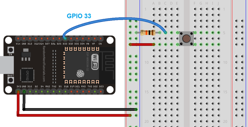
(This schematic uses the ESP32 DEVKIT V1 module version with 30 GPIOs – if you’re using another model, please check the pinout for the board you’re using.)
Note: only RTC GPIOs can be used as a wake up source. Instead of GPIO 33, you could also use any RTC GPIO pins to connect your button.
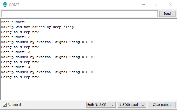
Let’s test this example. Upload the example code to your ESP32. Make sure you have the right board and COM port selected. Open the Serial Monitor at a baud rate of 115200.
Press pushbutton to wake up ESP32.
Try this several times, and see the boot count increasing in each button press.
Using this method is useful to wake up your ESP32 using a pushbutton, for example, to make a certain task. However, with this method you can only use one GPIO as wake up source.
What if you want to have different buttons, all of them wake up the ESP, but do different tasks? For that you need to use the ext1 method.
The ext1 allows you to wake up the ESP using different buttons and perform different tasks depending on the button you pressed.
Instead of using the esp_sleep_enable_ext0_wakeup() function, you use the esp_sleep_enable_ext1_wakeup() function. In the code, that function is commented:
// If you were to use ext1, you would use it like
// esp_sleep_enable_ext1_wakeup(BUTTON_PIN_BITMASK,ESP_EXT1_WAKEUP_ANY_HIGH);
Uncomment that function so that you have:
esp_sleep_enable_ext1_wakeup( BUTTON_PIN_BITMASK,ESP_EXT1_WAKEUP_ANY_HIGH);
The first argument of the function is a bitmask of the GPIOs you’ll use as a wake up source, and the second argument defines the logic to wake up the ESP32.
In this example we’re using the variable BUTTON_PIN_BITMASK, that was defined at the beginning of the code:
#define
BUTTON_PIN_BITMASK
0x200000000
// 2^33 in hex
This is only defining one pin as a wake up source, GPIO 33. You need to modify the bitmask to configure more GPIOs as a wake up source.
To get the GPIOs bitmask, follow the next steps:
Mask for a single GPIO
For you to understand how to get the GPIOs bitmask, let’s go through an example. In the code from the library, the button is connected to GPIO 33. To get the mask for GPIO 33:
1. Calculate 2^33. You should get 8589934592 ;
2. Convert that number (8589934592) to hexadecimal. You can go to this converter to do that:
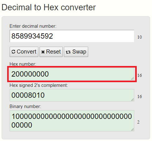
3. Copy the Hex number to the BUTTON_PIN_BITMASK variable, and you should get:
#define BUTTON_PIN_BITMASK 0x200000000 // 2^33 in hex
Mask for several GPIOs
If you want to use GPIO 2 and GPIO 15 as a wake up source, you should do the following:
#define BUTTON_PIN_BITMASK 0x8004
When you use several pins to wake up the ESP32, it is useful to know which pin caused the wake up. For that, you can use the following function:
esp_sleep_get_ext1_wakeup_status()
This function returns a number of base 2, with the GPIO number as an exponent: 2^(GPIO). So, to get the GPIO in decimal, you need to do the following calculation:
GPIO = log( RETURNED_VALUE )/log( 2)
Now, you should be able to wake up the ESP32 using different buttons, and identify which button caused the wake up. In this example we’ll use GPIO 2 and GPIO 15 as a wake up source.
Wire two buttons to your ESP32. In this example we’re using GPIO 2 and GPIO 15, but you can connect your buttons to any RTC GPIOs.
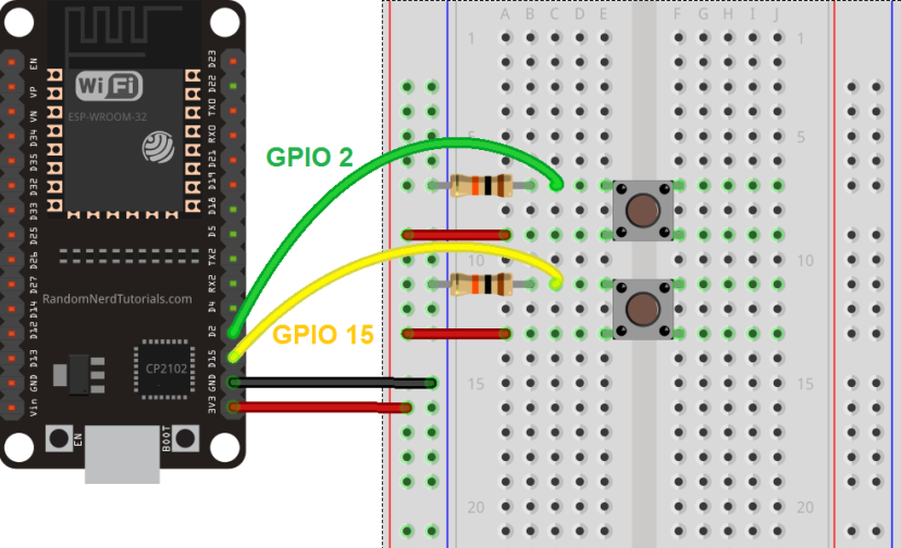
You need to make some modifications to the example code we’ve used before:
The next sketch has all those changes implemented.
/*H*******************************************************
Deep Sleep with External Wake Up
=====================================
This code displays how to use deep sleep with
an external trigger as a wake up source and how
to store data in RTC memory to use it over reboots
This code is under Public Domain License.
Hardware Connections
======================
Push Button to GPIO 33 pulled down with a 10K Ohm
resistor
NOTE:
======
Only RTC IO can be used as a source for external wake
source. They are pins: 0,2,4,12-15,25-27,32-39.
Author:
Pranav Cherukupalli <cherukupallip@gmail.com>
********************************************************/

//************************* DEFINES ************************************
#define BUTTON_PIN_BITMASK 0x8004

//************************* PROTOTYPES ************************************
void print_wakeup_reason();
void print_GPIO_wake_up();

//************************* VARIABLES ************************************
RTC_DATA_ATTR int bootCount = 0;              // GPIOs 2 and 15

/*F********************************************************************
*
**********************************************************************/
void
setup()
{
	Serial.begin( 115200 );
	delay( 1000 );
	// Take some time to open up the Serial Monitor Increment boot number and
	// print it every reboot
	++bootCount;
	Serial.println( "Boot number: " + String( bootCount) );
	print_wakeup_reason();                  // Print wakeup reason for ESP32
	// Print GPIO used to wake upprint_GPIO_wake_up();
	/********************************************************
	1st configure wake up source, set ESP32 to wake up for an external trigger.
	There are two types for ESP32, ext0 and ext1.  ext0 uses RTC_IO to wakeup
	thus requires RTC peripherals to be on while ext1 uses RTC Controller so
	doesnt need peripherals to be powered on.  Note that using internal
	pullups/pulldowns also requires RTC peripherals to be turned on.
	********************************************************/
	// esp_deep_sleep_enable_ext0_wakeup(GPIO_NUM_15,1); // 1 = High, 0 = Low
	// If you were to use ext1, you would use it
	likeesp_sleep_enable_ext1_wakeup( BUTTON_PIN_BITMASK
		, ESP_EXT1_WAKEUP_ANY_HIGH);
	// Go to sleep now
	Serial.println( "Going to sleep now");
	delay( 1000 );
	esp_deep_sleep_start();
	Serial.println( "This will never be printed");
}
/*F********************************************************************
*
**********************************************************************/
void
loop()
{
	//This is not going to be called
}
/*F********************************************************************
* Method to print the reason by which ESP32 has been awaken from sleep
**********************************************************************/
void
print_wakeup_reason()
{
	esp_sleep_wakeup_cause_t wakeup_reason;
	 wakeup_reason = esp_sleep_get_wakeup_cause();
	switch( wakeup_reason)
	{
		case ESP_SLEEP_WAKEUP_EXT0:
			Serial.println( "Wakeup caused by external signal using RTC_IO");
			break;
		case ESP_SLEEP_WAKEUP_EXT1:
			Serial.println( "Wakeup caused by external signal using RTC_CNTL");
			break;
		case ESP_SLEEP_WAKEUP_TIMER:
			Serial.println( "Wakeup caused by timer");
			break;
		case ESP_SLEEP_WAKEUP_TOUCHPAD:
			Serial.println( "Wakeup caused by touchpad");
			break;
		case ESP_SLEEP_WAKEUP_ULP:
			Serial.println( "Wakeup caused by ULP program");
			break;
		default:
			Serial.printf( "Wakeup was not caused by deep sleep: %d\n"
				, wakeup_reason );
			break;
	}
}
/*F********************************************************************
* Method to print the GPIO that triggered the wakeup
**********************************************************************/
void
print_GPIO_wake_up()
{
	uint64_t GPIO_reason = esp_sleep_get_ext1_wakeup_status();
	Serial.print( "GPIO that triggered the wake up: GPIO ");
	Serial.println( (log(GPIO_reason))/log( 2), 0);
}
You define the GPIOs mask at the beginning of the code:
#define BUTTON_PIN_BITMASK 0x8004 // GPIOs 2 and 15
You create a function to print the GPIO that caused the wake up:
/*F********************************************************************
*
**********************************************************************/
void
print_GPIO_wake_up()
{
	int GPIO_reason = esp_sleep_get_ext1_wakeup_status();
	 Serial.print( "GPIO that triggered the wake up: GPIO ");
	Serial.println( (log( GPIO_reason))/log( 2), 0);
}
And finally, you enable ext1 as a wake up source:
esp_sleep_enable_ext1_wakeup(BUTTON_PIN_BITMASK,ESP_EXT1_WAKEUP_ANY_HIGH);
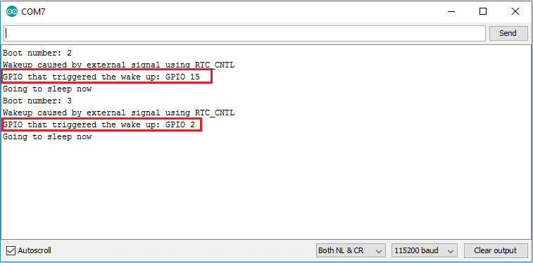
Having two buttons connected to GPIO 2 and GPIO 15, you can upload the code provided to your ESP32. Make sure you have the right board and COM port selected.
The ESP32 is in deep sleep mode now. You can wake it up by pressing the pushbuttons.
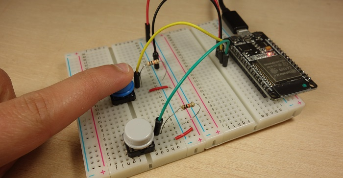
Open the Serial Monitor at a baud rate of 115200. Press the pushbuttons to wake up the ESP32.
You should get something similar on the serial monitor.
In this article we’ve shown you how to use deep sleep with the ESP32 and different ways to wake it up. You can wake up the ESP32 using a timer, the touch pins, or a change on a GPIO state.
Let’s summarize what we’ve seen about each wake up source: