| | |
|
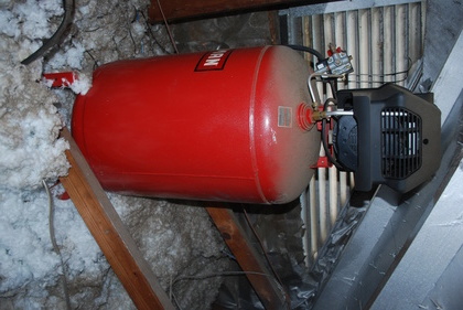
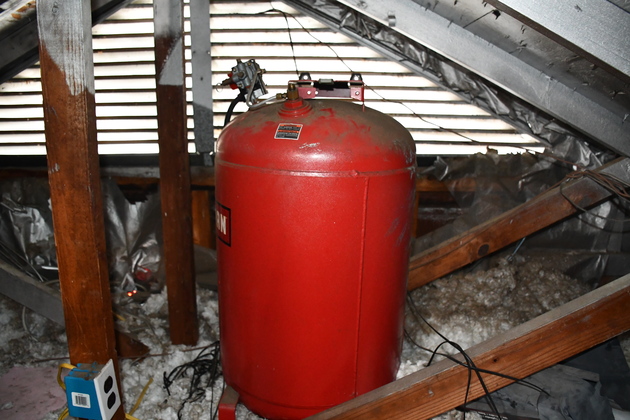
Original Sears Compressor in shop attic
|
|
|
|
Replacing Air Compressor Pump & Motor for Sears 919.167312
|
12/04/2021 Page Origin
I don't use my air compressor heavily, but when I need it nothing else will work!
I blow out the DC6 filter several times each year, occasionally I air up a tire, some times I need to use some of my impact tools and I occasionally do a little spray painting.
This Sears oil free air compressor has been installed in the attic above my workshop (was garage) for about 19 years (since 2003).
Note: this oil free compressor is awfully noisy!
This year (2021) it has broken twice, the rear cover (black plastic) containing the run/start caps and the centrifugal switch, pops off.
When this rear cover poped off, the centrifugal switch was no longer in it's start position, so I got a Locked Rotor Amperage (LRA) current drain that tripped the 20 Amp breaker.
After the second breakdown in 1 year, I had to do something about an air compressor, I need more reliabilty.
The Sears system's (919.167312) has a 30 gal. tank (certified above 150#), and is already plumbed into my air distribution system.
My air distribution system includes a water trap (all water in the tank & system drained into it) with blow out valve, guages, and valves to allow me to cut portions of the system out, etc.
Since the Sears compressor was an oil free system, that is, the compressor was mounted directly to the motor's shaft, I had to replace the pump and motor.
I found a couple of motors that purported to be a direct replacement for the Sears, but they were very pricy, and I didn't feel good about their write ups!
So I went hunting.
I checked Harbor Freight, they had a pump with good pressure but low SCFM (for impacts anyway).
Then I looked on Amazon.
Most air compressor pumps I find, in my price range, are only spec'd to 115 PSI, which means a new pressure switch.
These pumps do have a high SCFM though, so much better for impact tools.
The Sears tank and check valve has a pressure unloader, are rated for 150# plus, so I won't have to worry about that.
BTW, the outlet on the Sears tank is in the bottom of a hemisphere so all the water is drained, hence the tank's interior shouldn't be very rusty!
The existing pressure switch is a Siemens D26612, which is set for 150# cut-out and what I can find on the internet says, it can't be adjusted.
Pieces required, Pump, motor, pulley, belt, pressure switch, and a 240V 20A circuit with receptical, wire, plug, box and cover plate.
- Pump: 3HP, 2 Piston, V Style, single stage, Twin Cylinder Air Compressor Head Pump.
TL31105 Dims: 15 x 11 x 12.5 " (LxWxH), delivers 8.8 CFM.
Note this is a "Compressor Duty" motor, hence it will require a higher current circuit then the other 3HP motors in the shop.
- Motor: 3HP Air Compressor Motor 3450 RPM, Single Phase 56 Frame 208-230V 5/8" Shaft 60Hz CW/CCW TEFC
Motor Dims: 15.75 x 10.63 x 10.43 " (LxWxH).
- 3" Sheave (AKA: Pulley): Single Groove Web Sheaves, 3"OD 5/8"Bore V-Belt Sheave with key
- Belt: 48" v-belt
- Pressure Switch with unloader. LF10-4M.
- New 240 Volt, 30 amp circuit (NEMA L6-30R and Nema L6-30p connectors)
(similar to what I did for the DC6 Blower Upgrade) click on "New 240V Ckt", with the exception of 30Amps instead of 20Amps.
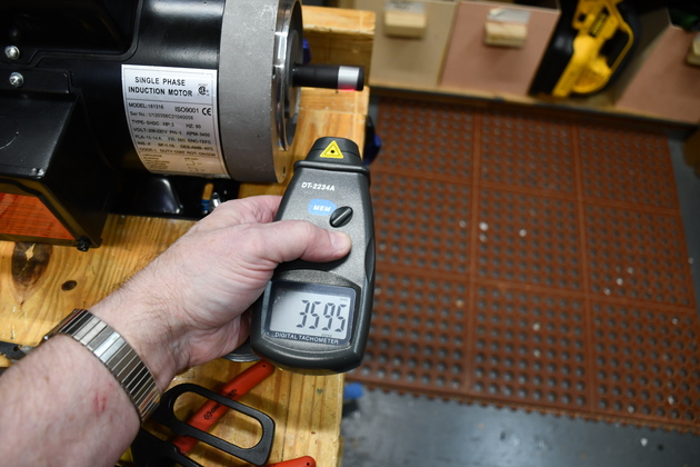
During initial testing: I'm getting 3570 RPM on the motor and 1064 RPM on the pump.
Compressor Oil: 20 or 30 weight, non detergent, not engine oil.
It took about 16oz. (≅500ml) to fill the compressor's crank case.
Tube Flair: 45° angle. American.
Pipe Flair: 37° angle. Japanese
Specifications for Superbuy TL31105 compressor pump.
Max Air Pressure 115 PSI
Speed: 1080RPM
Max Air Delivery: 8.8 CFM
Flywheel diameter: 9.8"(250MM)
Mounting hole: M8
Required oil: air compressor lubricating oil (16 oz.)

|
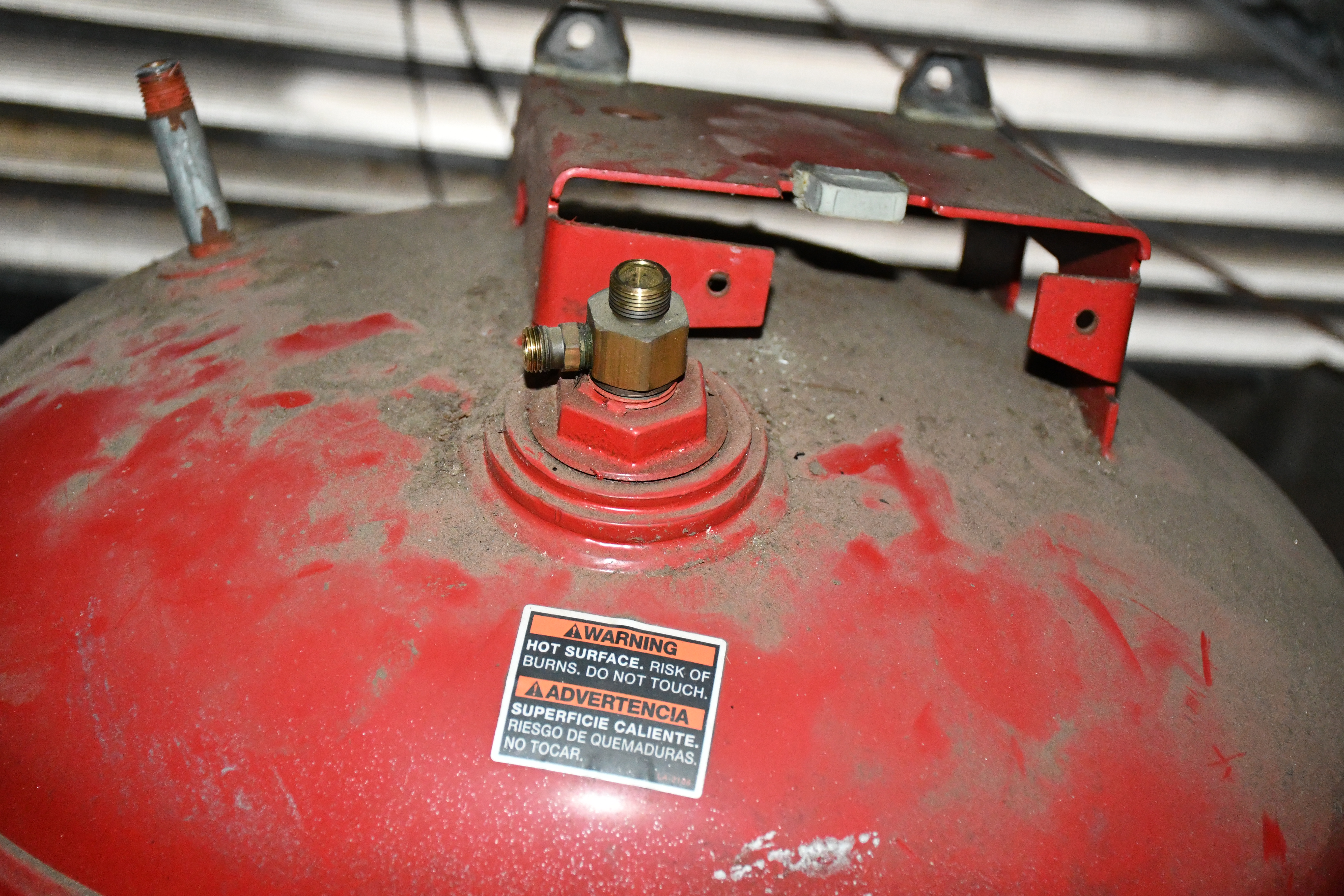
Air Tank in Shop Attic
We mounted it with the elongated tank vertical.
The bottom hemisphere had a plug which we replaced with a 1/2" bushing and PVC adapter.
The 1/2" PVC gently angles down to the top of the Water Trap.
|
|
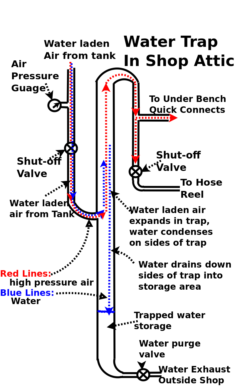
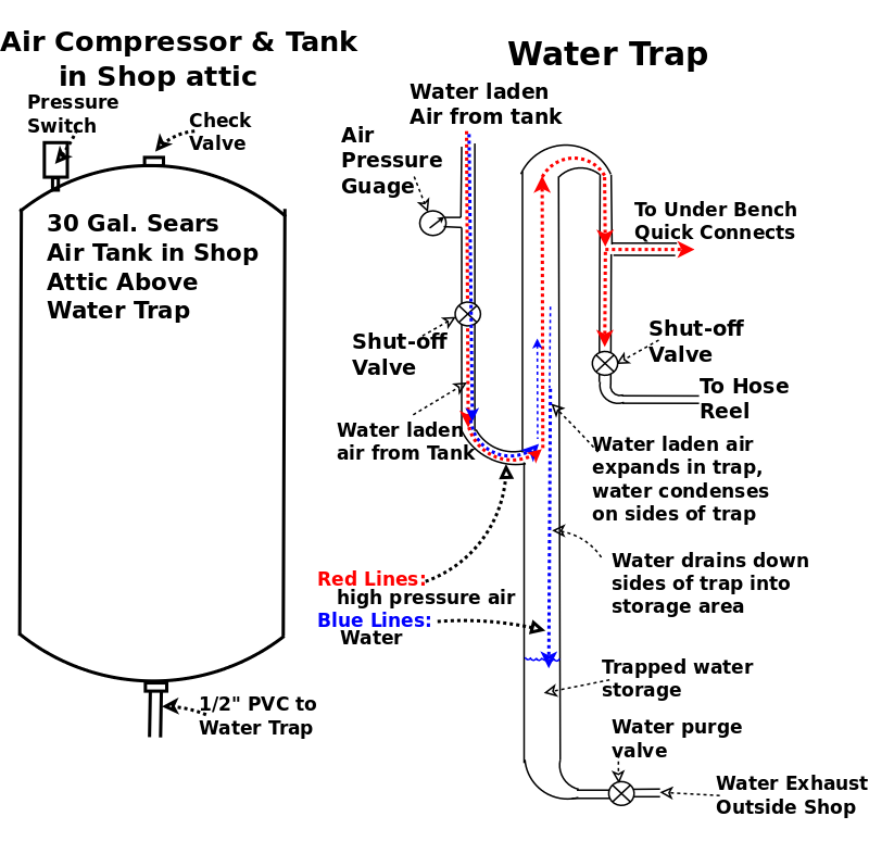
Simple Water Trap.
Click to enlarge then follow the dotted red and blue lines.
The high pressure air flows down from the compressor tank (1/2" PVC), into the water trap (1" PVC), then up through the water trap, at a slower speed (thanks to Bernoulli's Law) and out the top, allowing most of the suspended water to condense on the sides of the water trap and collect in the bottom half.
The water collects in the lower half of the 1" 8ft. tall PVC.
After exiting the top of the water trap, the air goes down through another 1/2" PVC, to the outlets plumbed in the shop under the front of the benches and to a hose reel with it's own cutoff.
At the bottom of the water trap (1" PVC) is a water purge or drain valve and a water exhaust line to the outside.
This drain valve is used periodically to exhaust the water out of the water trap.
An even larger water trap PVC would be appropriate, but I could only find PVC tees etc. from 1/2" to 1".
Remember, compressed air plumbing is like sewer plumbing, water has to flow smoothly, by gravity, to a chosen low point where it collects.
Click for larger Pic.
|
|
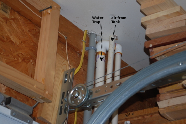
Here you can see the 1/2" PVC coming through the ceiling, and the top end of the water trap (output).
The grey PVC is for electrical power to the outside motion detector lights.
|
|
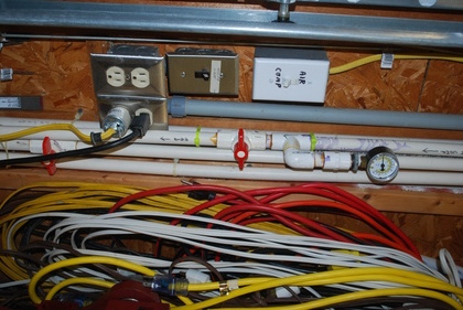
Air guage, main valve (upper red handle), and the other lines running up and down the wall.
My water trap (behind tee and main valve) is almost 8' tall.
Lower red handled valve in the pic, controls air to a hose reel on the ceiling, a cronic leaker, so it has it's own shut-off valve.
Switches on the wall.
The top switch controls the air compressor in the attic, I keep it off most of the time, since I don't use it often.
The bottom switch controls power to the motion controlled car port lights and a motion controlled light in the back yard.
|
After doing a lot of reearch I believe I have found a working solution.
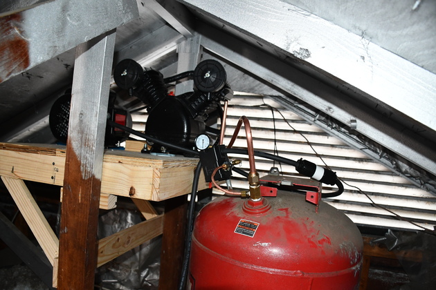
I plan to get a new motor, pump, sheave, pressure switch, and belt, mount them on a wooden frame that will be screwed between two truss uprights, adjacent to the compressor tank's top.
In the pic below, the new base will be attached between the two verticals on the left of the tank.
The 3HP motor from Amazon, 3450 RPM.
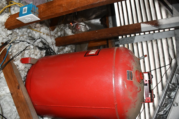
Attic 30 gal. Air Tank
|
The tank in 2021, with motor/pump removed.
This tank, even though its been in use since 2003, should not have a lot of internal rust, since water has never been allowed to accumulate inside.
Note, it is elongated vertically, the air outlet ls in the bottom with a constant downward angle to the water trap, in the shop below.
Note the original 120V receptical near the bottom of the truss vertical.
The new motor/pump mount will be attached between the two verticals to the left of the tank.
|

|
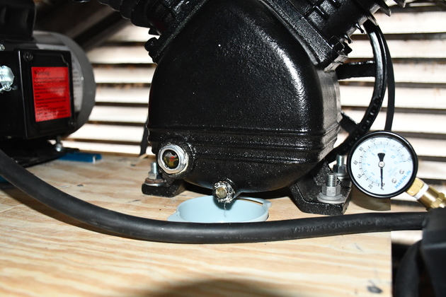
Check valve (center) and pressure switch nipple (left).
Also note 19 years of dust on top of the 30gal. tank.
This check valve has a 3/8" MNPT, and I want to use 1/2" tube to connect the new pump to this tank, so I'm replacing the in-tank check valve.
The original pressure switch isn't supposed to be adjustable, so I'm replacing it also.
Note: since the tank and compressor will be mounted seperately, I'll need a flexible 1/2" pipe to connect them, to prevent vibration fatigue cracking the tube.
|
Motor

|
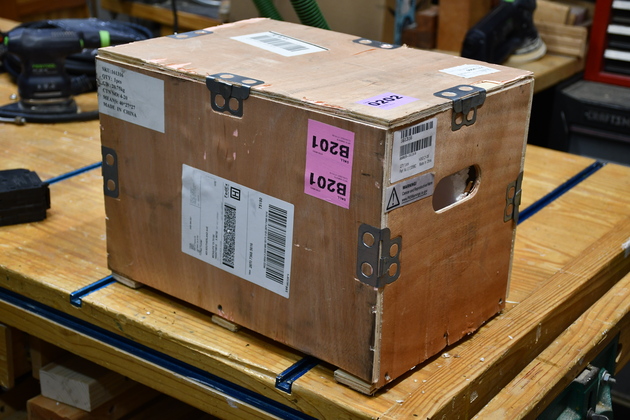
Wooden shipping box containing the 3HP motor.
|
|
Closer look at the wooden motor shipping box.
Note the handhold.
|
|
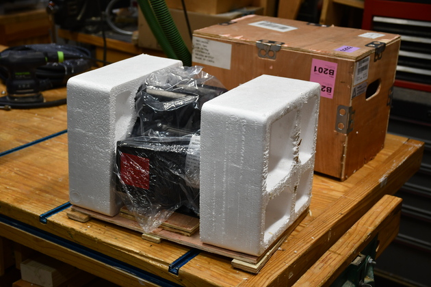
Remove 8 wallboard screws and lift off the box.
Note styrofoam and plastic wrap.
I was very impressed with the motor's packaging, it beat the heck out of the Jet motors I received.
|
|
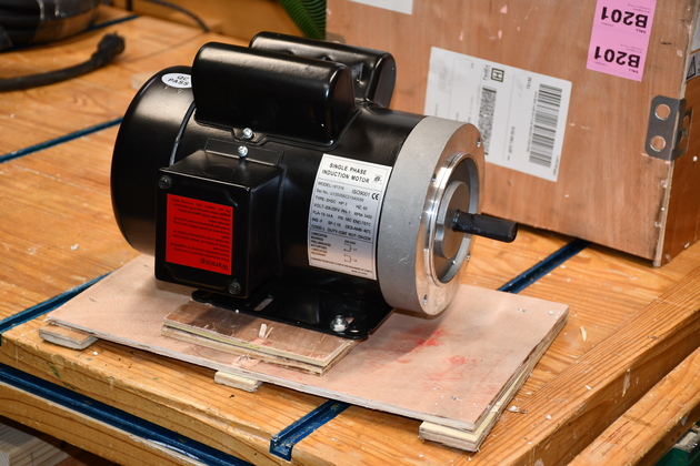
Plastic removed.
Motor held down with two 8mm hex bolts.
|
|
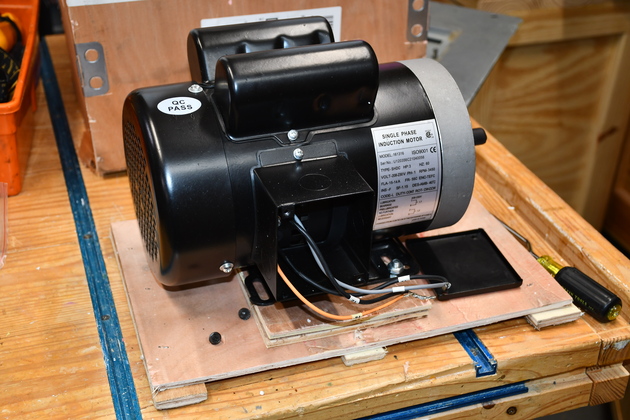
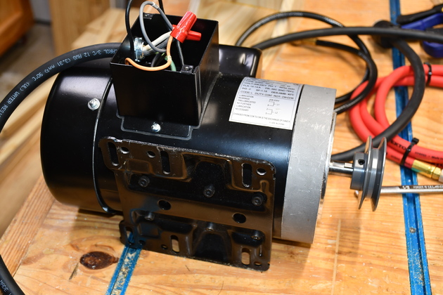
The new 3HP 240V motor, it came in a really interesting wooden box.
The motor is bolted to the box bottom, you can see the rest of the box hehind the motor.
The wires have little tags on them, labeled: T1, T8, T2, T5.
From the factory, the motor is wired to rotate CCW, T1 and T8 are twisted together, and T2 and T5 are also twisted together, these two would be connected to the 240V single phase.
|
|
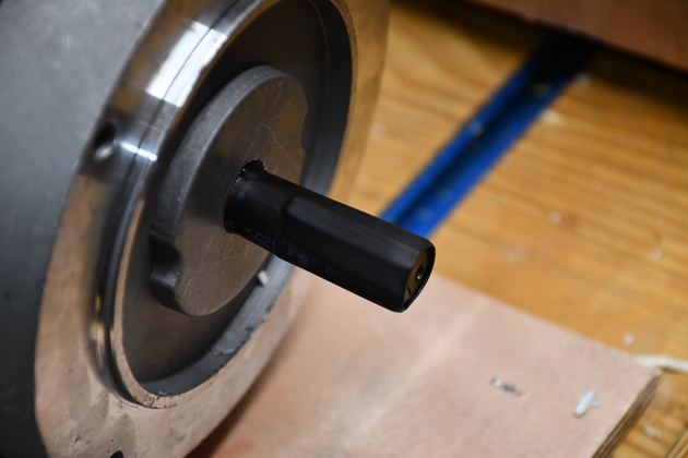
The motor was shipped with, what appears to be, heat shrink on it's 5/8" shaft.
You can see the imprint of the key in the heat shrink.
|

|
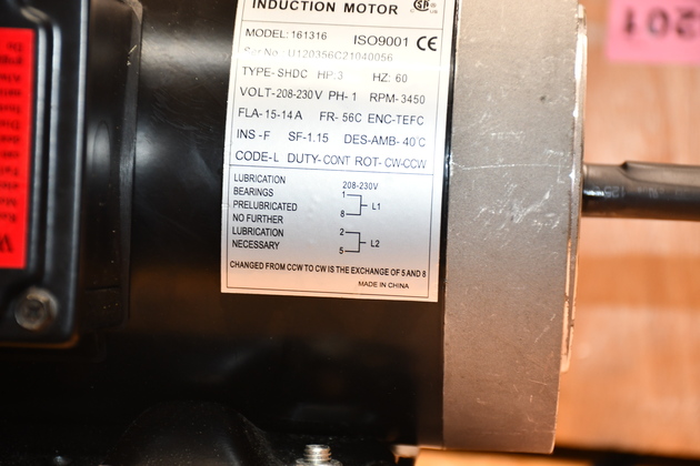
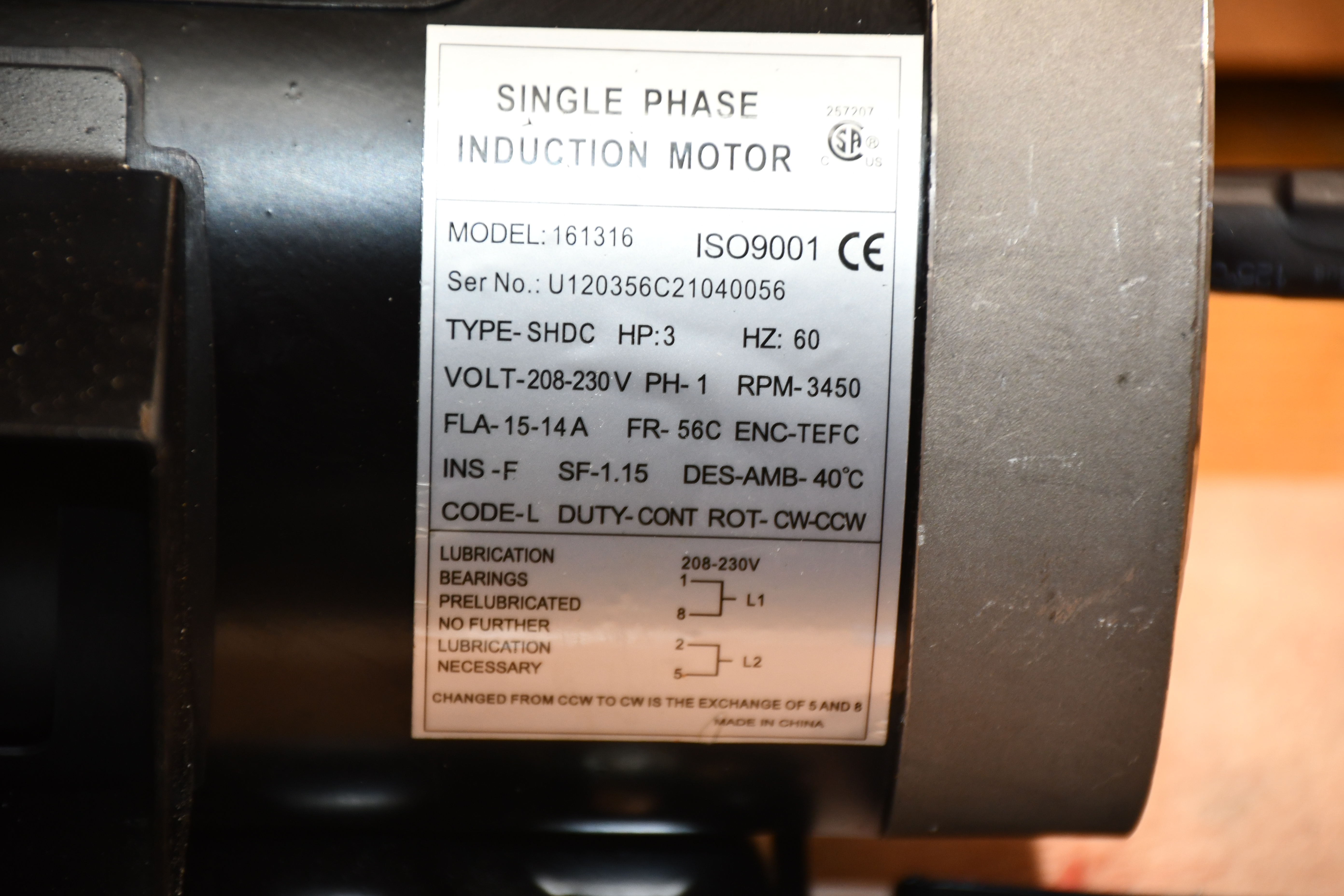
The motor's tag.
FLA: 15 -14A. Overload protection 15 * 1.25 = 18.75A
Service Rating: 1.15
|
|
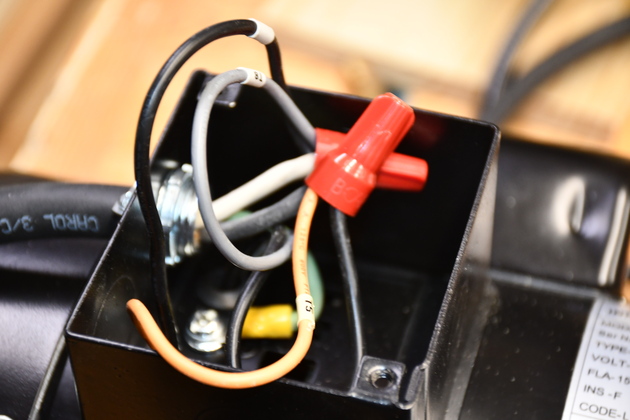
Better pic of wiring.
My motor was shipped wired for CCW rotation (T1 to T8 and T2 to T5), to reverse the motor's direction, wire T1 to T5 and T2 to T8.
|
Pump
|
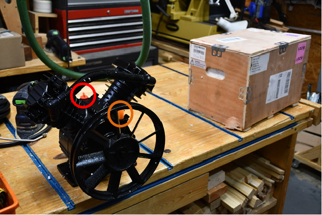
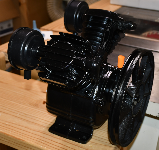
The TL31105 pump has arrived sitting next to the unpacked motor's wooden box.
Note the Red Circle around the oil filler and the Orange Circle around the air vent.
One of the keen things about this particular pump is it has a seperate filler and vent, plus a sight glass.
|
|
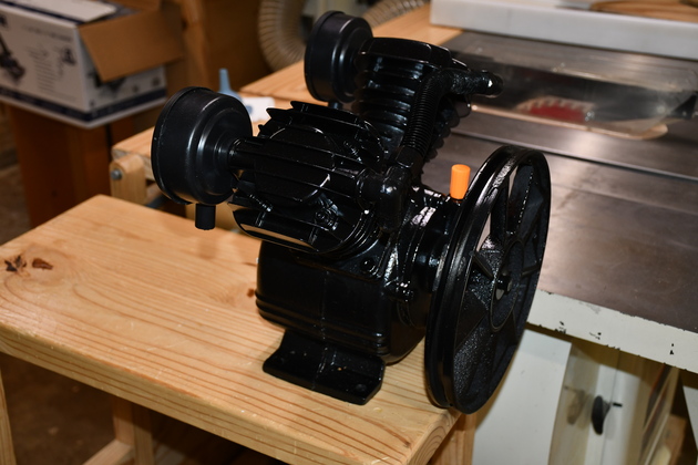
Pump on my roll-around table.
|
|
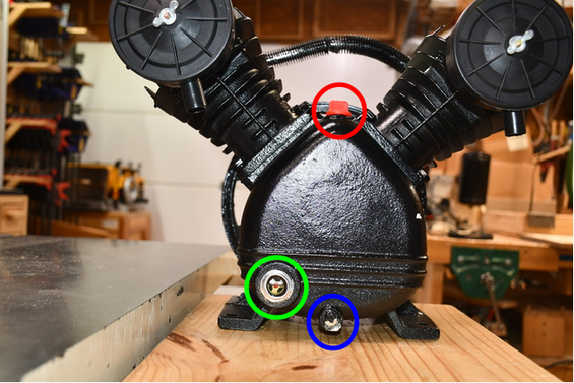
Back of the pump showing (Red Circle) fill cap (top), sight glass (Green Circle), and drain plug (Blue Circle).
The pump came with no oil, so I filled it up to the center of the sight glass.
|
|
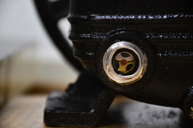
Close look at sight glass showing oil level.
It took a little over 16oz. (≅500ml), about 1/2 qt., to fill the compressor's crank case.
|
|
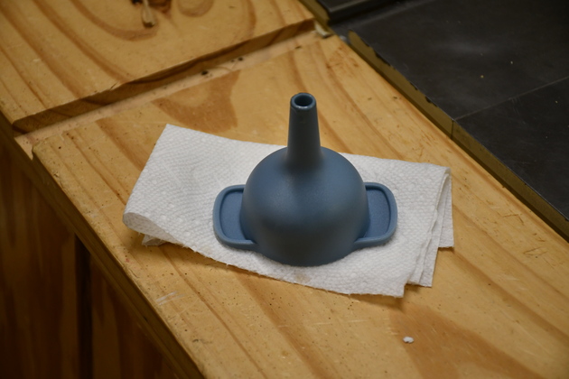
Funnel used to fill pump's crankcase.
This is the smallest funnel in the set, It's tip will actually screw partway into the compressor's oil fill hole.
|
Pairing Motor & Pump

|
Test lash up on my work bench.
Note the 1" Tee bolts in the Tee tracks are securing both pump and motor.
Tension the belt:
Put 5 LB pressure on the center of the belt (between flywheel and sheave) should deflect ≤ 1/2" or 3/16" on some systems.
Some belts say deflect 1/64" for each 1" of span.
|
|
Checking the motor is 3595 RPM, unloaded.
I put a piece of reflective tape on the shaft so the optical tach would work.
|
|
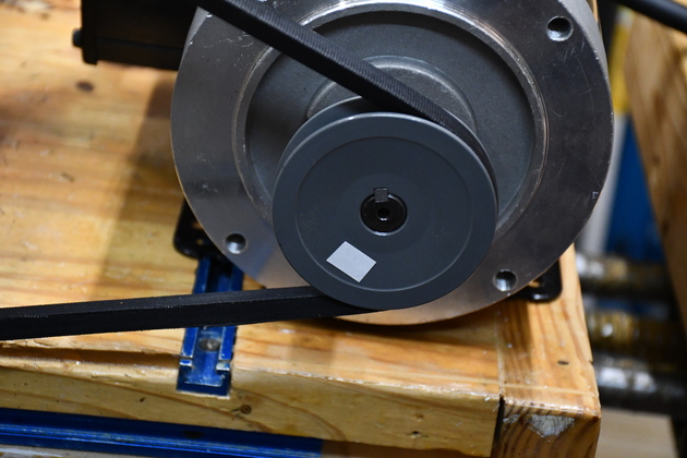
Reflective tape on the 3" motor sheave.
|

|
Reflective tape on the pump flywheel.
|
|
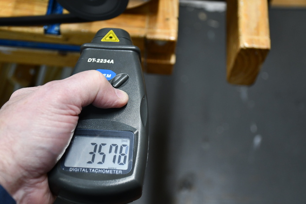
Motor: 3576 RPM.
This is a: TL31105, Single Phase General Purpose Induction Motor: HP - 3,POLE - 2,FRAME -56C, ENC -TEFC,IP - 55.
HZ: 60Hz, Voltage: 208V/230V,AMP: 15.0-14.0A,RPM: 3450-3600.
44.9 LBS.
|
|
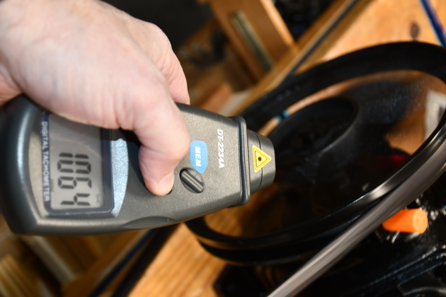
Pump: 1064 RPM.
|
Pressure Switch
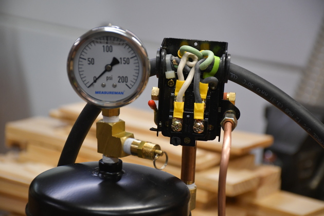
|
Close up of the pressure switch on the test setup.
The switch is actually mounted upside-down, the two adjustments can barely be seen at it's bottom.
For more details along with adjusting, please see Pressure Switch * Prtable Air Tank page.
|
Electric
The circuit:
The existing circuit for the old compressor is a 120Volt 20Amp, on a home run from the breaker box.
It will need to be replaced with larger conductors (10-3 Wgnd ideally), 30 Amp 240V plugs/recepticals, and a new quad breaker (20,30,30,20).
20Amps would let the motor run but would trip out during starting the motor due to its poentially starting under load.
Compressor Duty means running continuously and starting under max load.
I'll have to move the ceiling reel to the East junction box, then run a new home run from the breaker box to the receptical box in the attic near the compressor's 30 gal. tank.
Which means a new quad 30a breaker, a new 10 AWG home run from the breaker box, a new 240V switch, a new 240V 30A recptacle and a new cover plate for the recptacle.
Since this 240V line is single phase, I can use 10/2 W GND, with red tape on bothe ends of the white wire.
I had to use a Square D breaker for the DC6 blower.
I have noticed that some manufacturers add a little piece of plastic or metal (not electrified) so the breaker won't sit snugly in the slot of a different manufacturer's breaker box.
I assume they are trying to restrict me to only use their boxes and breakers.
If your house is an old one, like mine, that means you have to have your breaker box and all the breakers replaced, BIG $$$$$$$.
However after some careful examination and testing, I have found I can use Square-D HOM breakers in my old Gould box if I snip out a little bit of plastic above the buss bar contact slot.
For the in-wall wire run, I'll use what I call "Flat Patching".
|
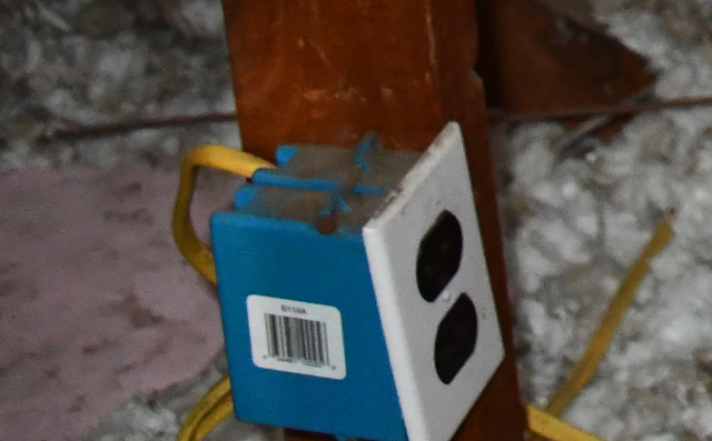
The 120V 20A plug, in the attic, for the Sears air conpressor.
I'll rewire that for 240V 30A, single phase and a NEMA L6-30A receptacle and cover plate.
|
|
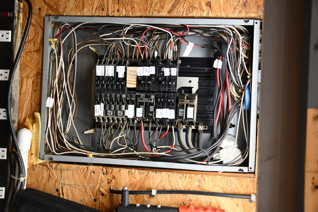
Ancient Gould breaker box, after installing two new 240V circuits.
Note the "Bad Slot", this is where one of the Gould breakers arced and ruined the 120V contact.
I have added 4 quad breakers to this guy in the last year, Shop AC, Air Comp, Dust 240, and Shop 240 (right under the mains.
You'll also note the red tape on some white wires, signifying they are hot (white wires in house wiring is normally return).
Click for larger pic.
|
|
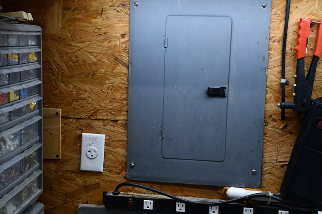
Breaker box wall with new Shop 240V receptical on the left.
|
|
Tank with old 120V receptacle (lower left).
The two vertical 2x4s on the left are the attic truss's verticals the new compressor mount will be attached to.
There is about 10" between the truss verts and the tank.
There is about 14" of clearance above the old pump mount on top of the tank, so the new compressor mount can overlap it quite a bit.
|
|
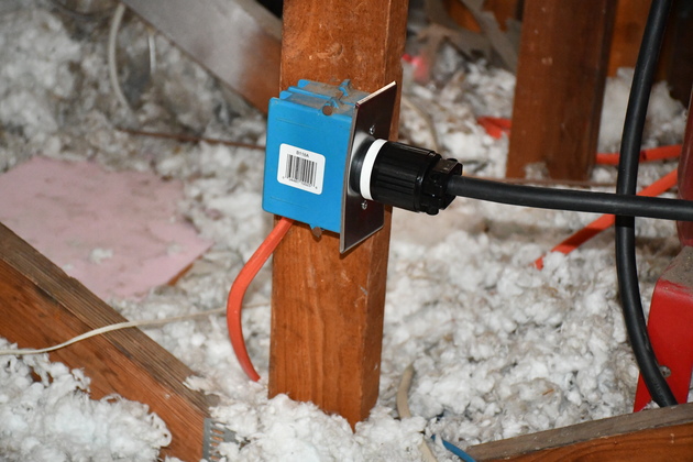
Closer look at the new 240Volt 30Amp receptacle, in the attic for the new compressor motor.
|
|
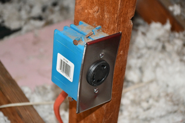
The 240V 30Amp Receptical.
|
|
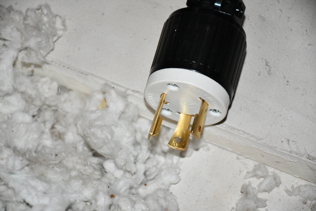
And new 240V 30A cable mount plug.
|
|
Wiring the motor.
Here, I'm attaching a 4' length of 12-3 SO cord to the motor, the other end will be attached to the pressure switch.
|
|
Closer look at motor wiring.
|


