| | |
|
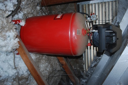
Original install of Sears oil free pump in the attic of my shop.
|
|
|
|
Original Install of Sears 919.167312
2 HP, 150 PSI Air Compressor (2003)
|
12/04/2021 Page Origin
I don't use my air compressor heavily, but when I need it, its really handy.
I blow out the DC6 filter several times each year, occasionally I air up a tire, some times I need to use some of my impact tools and I occasionally do a little spray painting.
This oil free air compressor has been installed in the attic above my workshop (was garage) for about 18 years.
Note: this oil free compressor is awfully noisy!
This year (2021 fall) it has broken twice, the rear cover (black plastic) containing the run/start caps and the centrifugal switch, pops off.
When this rear cover poped off, the centrifugal switch was no longer in it's start position, so I got a Locked Rotor Amperage (LRA) current drain that tripped the 20 Amp breaker.
After the second breakdown in 1 year, I had to do something about an air compressor.
The Sears system's (919.167312) has a 30 gal. tank (certified above 150#), and is already plumbed into my air distribution system.
My air distribution system includes a water trap (all water in the tank & system drained into it) with blow out valve, guages, and valves to allow me to cut portions of the system out, etc.
Since the Sears compressor was an oil free system, that is, the compressor was mounted directly to the motor's shaft, I had to replace the pump and motor.
I found a couple of motors that purported to be a direct replacement for the Sears, but they were very pricy, and I didn't feel good about their write ups!
|
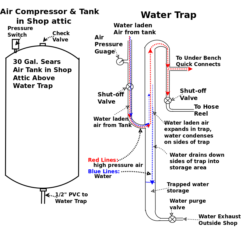
Diagram of my simple water trap.
Follow the dotted red and line.
The air flows down from the compressor tank (1/2" PVC), into the water trap (1" PVC), then up through the water trap, at a slower speed (thanks to Bernoulli's Law) and out the top, allowing most of the suspended water to condense on the sides of the water trap and collect in the bottom half.
The water collects in the lower half of the 1" 8ft. tall PVC.
After exiting the top of the water trap, the air goes down through another 1/2" PVC, to the outlets plumbed in the shop under the front of the benches and to a hose reel with it's own cutoff.
At the bottom of the water trap (1" PVC) is a water purge or drain valve and a water exhaust line to the outside.
This drain valve is used periodically to let the water out of the water trap.
An even larger water trap PVC would be appropriate, but I could only find PVC tees etc. from 1/2" to 1".
Remember, compressed air plumbing is like sewer plumbing, water has to flow smoothly, by gravity, to a chosen low point where it collects.
Click for larger Pic.
|
|
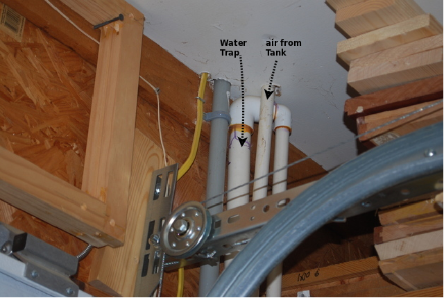
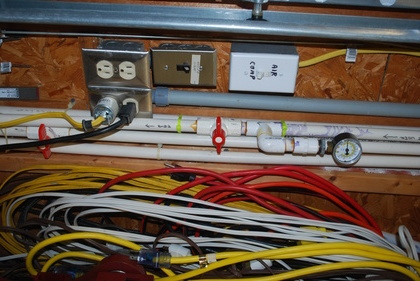
Here you can see the 1/2" PVC coming through the ceiling, and the top end of the water trap (output).
The grey PVC is for electrical power to the outside motion detector lights.
|
|
Air guage, main valve (upper red handle), and the other lines running up and down the wall.
My water trap (behind tee and main valve) is almost 8' tall.
Lower red handled valve in the pic, controls air to a hose reel on the ceiling, a cronic leaker, so it has it's own shut-off valve.
Switches on the wall.
The top switch controls the air compressor in the attic, I keep it off most of the time, since I don't use it often.
The bottom switch controls power to the motion controlled car port lights and a motion controlled light in the back yard.
|
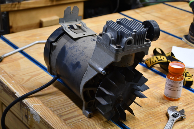
Old Motor
|
The 2HP craftsman motor and oil free pump, right side.
|
|
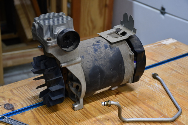
Left side.
Note I brought the high pressure air line (pipe) so I could make sure I have the right fittings for the new pump.
|
|
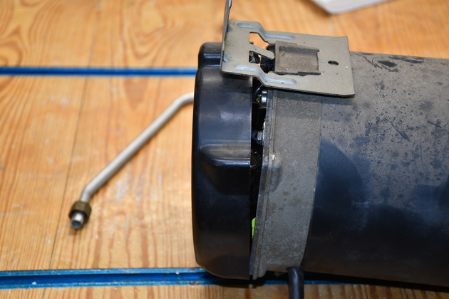
You can see the plastic cap housing the two capacitors and centrifugal switch, has broken loose again.
|
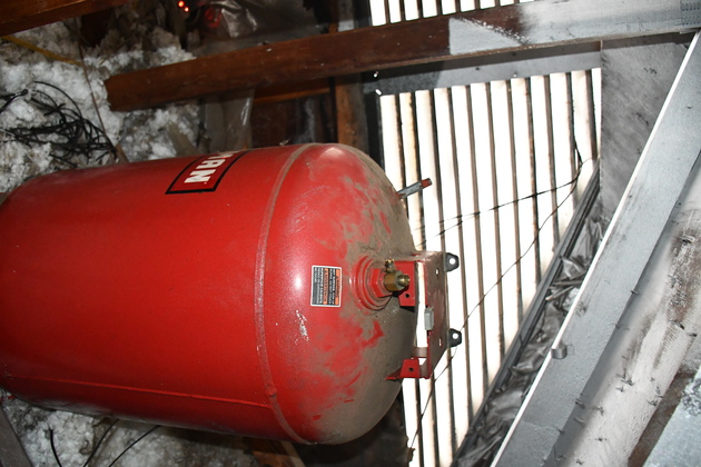
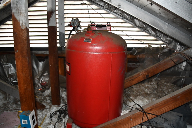
Tank
|
The tank, with motor/pump removed, and switches/valves.
Note you can see the 120V utlet on the truss vertical.
I'll rewire that for 240V 20A, single phase.
|
|
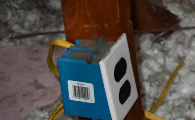
The 120V 20A plug for the Sears air conpressor.
|
|
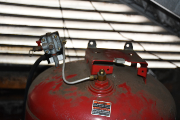
Closer look at the top of the tank.
You can see the pressure switch with the unload line going to the check valve on the tank.
The unloader bleeds off high pressure air when the pump is stopped, allowing the motor to restart, on the next cycle, with no back pressure.
|
|
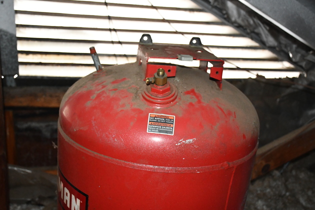
Better pic of tank top without pressure switch.
|
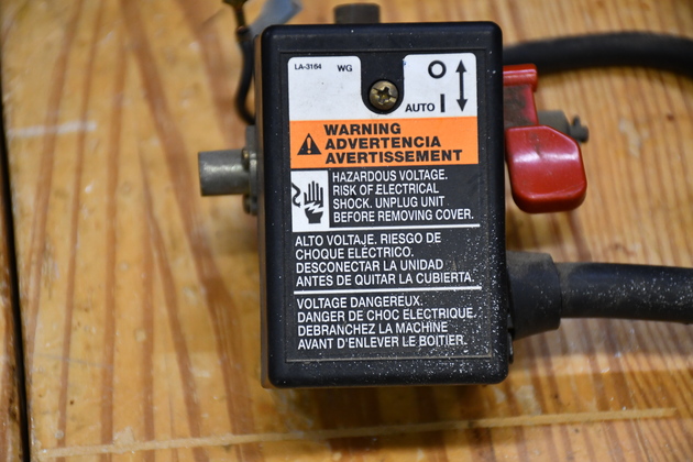
Pressure Switch
|
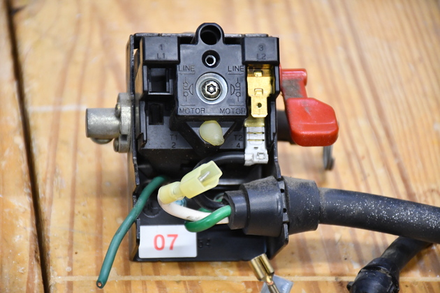
Inside of pressure switch.
This is a Siemens D26612 set at 150# cut out.
|
|
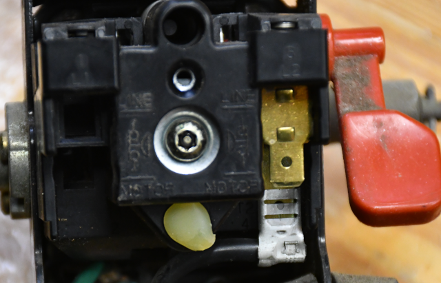
Every thing I've read about this switch says its not adjustable, yet I see, what appear to be, adjustments!
The pressure adjustment differential screw is probably the torx screw with a white ring around it.
The piece of glue below may cover the cut-out adjustment.
Note, this is only a singe phase switch (SPST), the two contacts on the right.
|
|
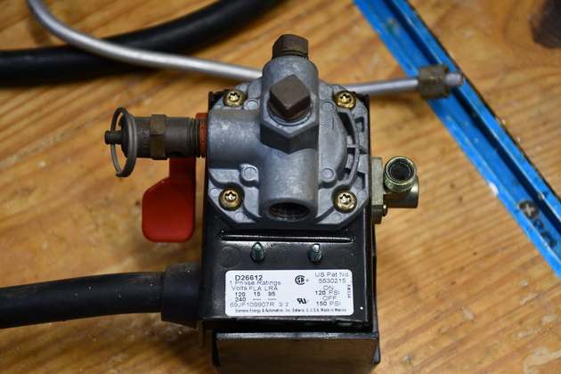
You can see all 4 ports, the left side has a safety valve in it, the small tube commector is for the unload tube to the check valve.
The 1/4" OD tube on the bench behind it is the unload tube.
Note the white tag at the bottom.
|
|
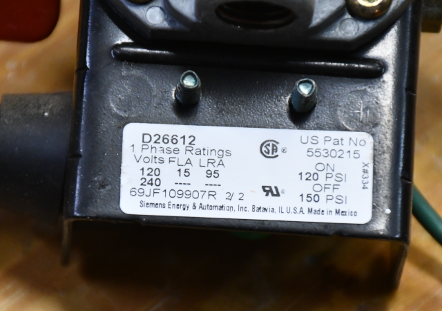
The white tag shows the model # D26612, its a single phase switch, the voltage (120/240), the current: Full Load Amps 15, Lock Rotor Amps 95, the cut-in pressure (120 PSI) and the cout-out pressure (150 PSI).
|
|
Outside of the cap.
|
|
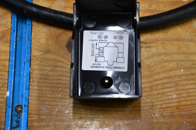
Wiring schematid inside the back cap.
|
Electric Circuit
The circuit:
The original circuit for the old compressor is a 120Volt 20Amp, on a home run from the breaker box.
|
|
The 120V 20A plug for the Sears air conpressor.
I'll rewire that for 240V 20A, single phase and a NEMA 6-20A receptacle.
|
|
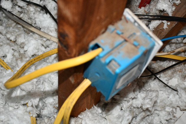
Old 120V 20A box with extra line to ceiling plug for cable reel.
|
