03/26.22: Page Origin
As of 04/08/22, I only have one thing more to do.
I need to replace the copper 1/2" tube from the compressor to the tank with a flexible tube.
Since the pump and tank are mounted seperately, and there is bound to be some vibration, a rigid tube would soom crack and begin to leak.
I've ordered a flexible tub that is tested to 200# pressure.
That should do the trick.
I've drilled a hole, in the base, under the pump's oil drain, and added a funnel, to make oil change easier and less messy.
|
|
| Since I can't take this into the attic fully assembled, I will take it in 3 parts, base, pump, and motor.
|
| Install the check valve and pressure switch on the tank.
| | Remove the motor and pump from the mount.
| | Move the mount into the attic and attach it to the truss uprights near the air tank.
| | Move the pump to the mount in the attic and install it.
| | Move the motor to the attic and install it on the mount.
| | Measure the length of the 1/2" tube from pump to tank.
| | Measure the length of the 1/8" unloader tube.
| | Cut & bend the ouput and unloader tubes.
| | Attach the pump's output (1/2" tube) to the check valve.
| | Connect the unloader tube between pressure switch and check valve.
| | Check for leaks.
|
|
Install
|
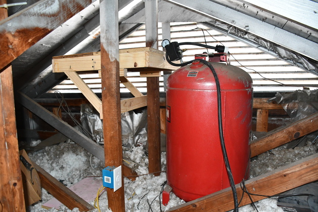
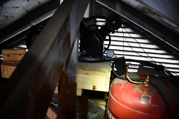
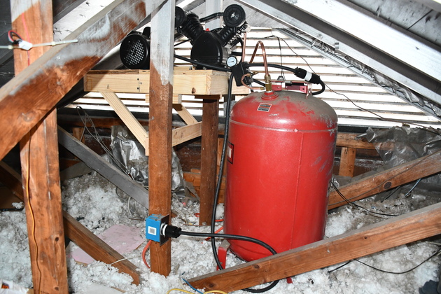
Compressor base installed next to the 30 gal. air tank.
You can see the 240V power plug just to the left of the 30 gal. tank, on the nearest truss vertical.
BTW, the silver stuff on the roof and rafters is spray on Radiant Barrier.
|
|
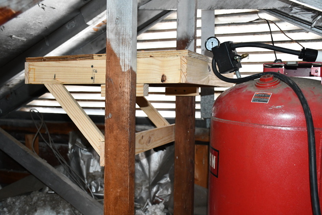
Closer look at the installed compressor base.
You are looking at the back side of the base.
|
|
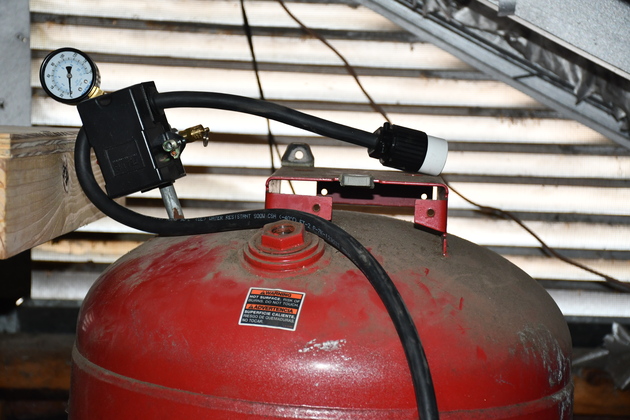
Close look, pressure switch installed.
Note 1/2" bushing (tank top foreground) for check valve, background 12-3 SO cable with female receptical is for motor, foreground 12-3 SO goes to 240V power plug.
|
|
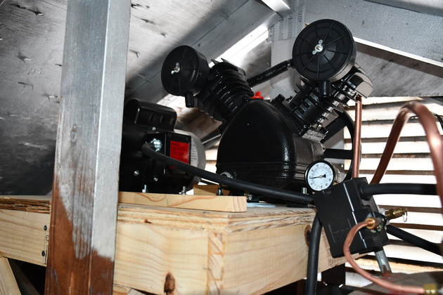
Pump & motor installed, now I need to work on the plumbing.
Note, the tank's check valve is already installed.
|
|
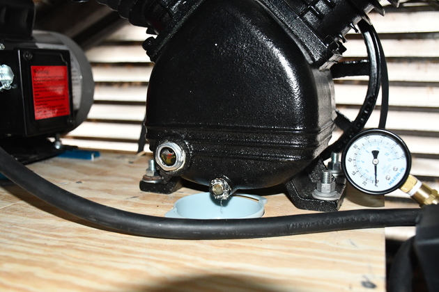
You can see the funnel directly under the pump's oil drain.
The sight glass is also easy to see, I hope this'll make an oil change easy..
|
|
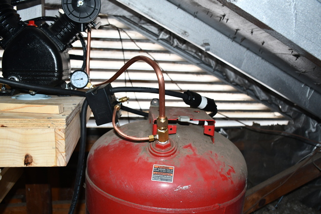
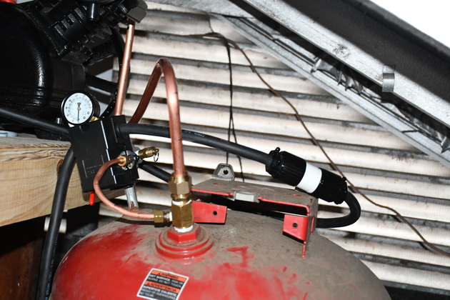
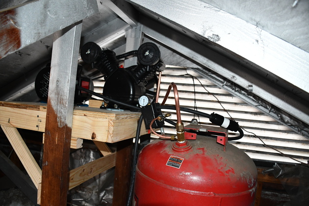
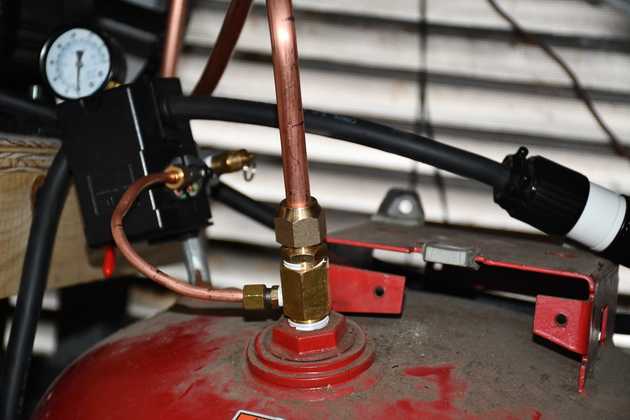
Now the plumbing is installed, the pump discharge (1/2" copper tube in center), and the unload tube, from pressure switch to tank's check valve.
|
|
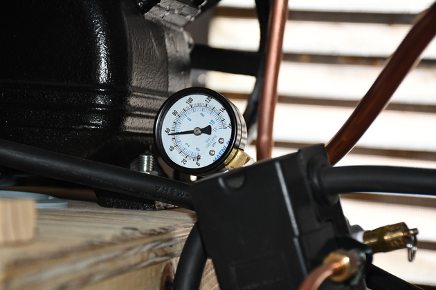
Note about 60 # pressure from yesterday's run.
|
|
Hooked up and ready to go.
|
|
Closer look at the pump and pressure switch.
|
|
Everything installed and ready to test.
|
|
Closer look at tank's check valve, compressor discharge, unloader tube from prepressure switch, and power to the motor (plug receptical on right).
|
New Electric
|
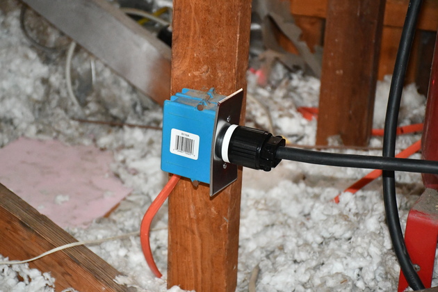
Heavy SO cord plugged into the new 30A 240V receptical.
|
|
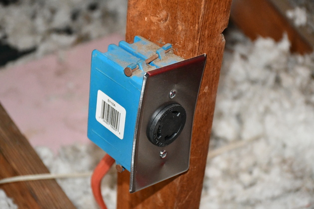
New 30A 240V receptical.
|
|
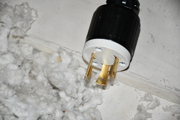
New 30A 240V plug.
|
In The Shop
|
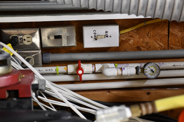
In the shop, Old switch and gauge, next to the overhead door.
Note the yellow romex and the old switch with ivory switch toggle.
|
|
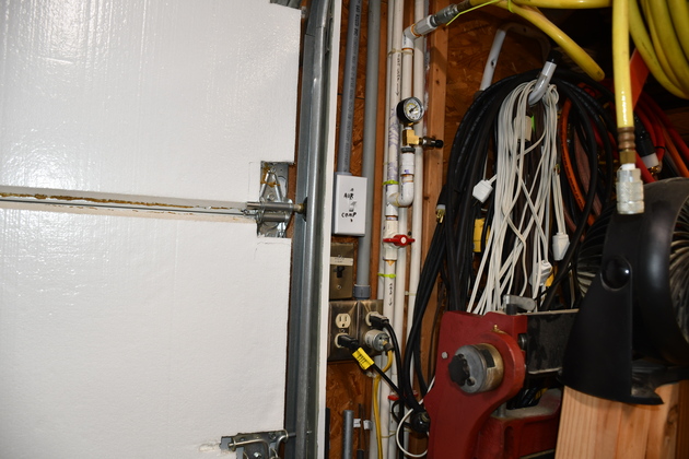
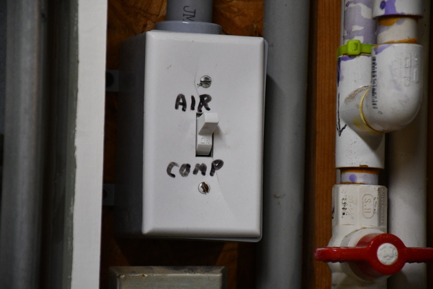
After installing the new AirComp.
|
|
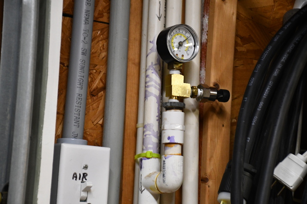
Closer look, note the new tee below the pressure gauge and new pressure sensor.
Also, not 120Lbs. pressure showing on the gauge.
|
|
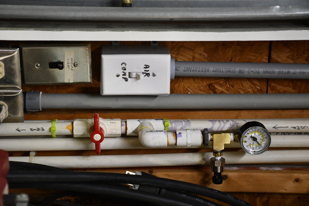
A little bit taller look at new 30 Amp switch and pressure sensor.
Note, I ran a 3/4" PVC conduit into the new box when I installed the new switch.
|
|
New 30 Amp switch (A DPST), I know it doesn't look different but it is.
|