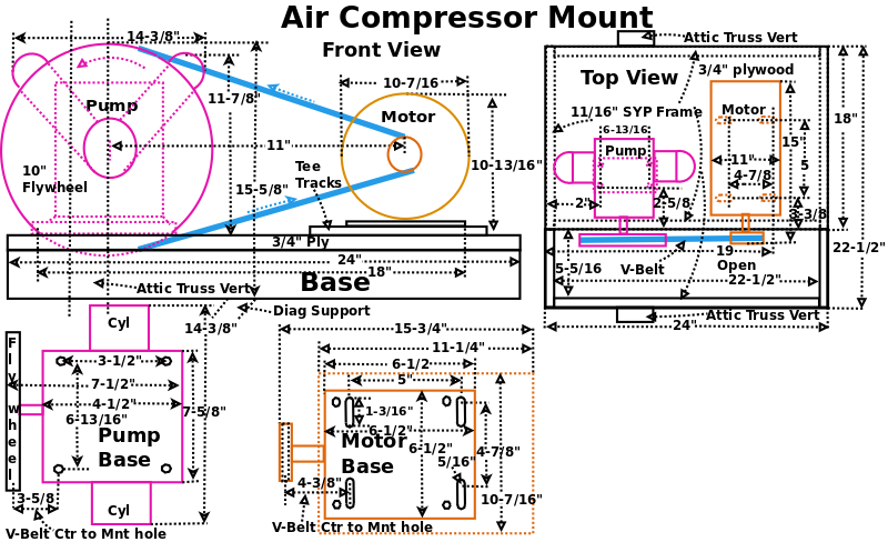
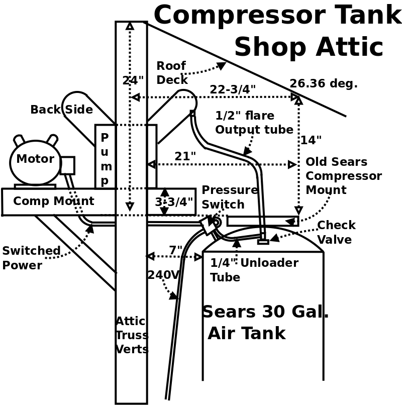
When I rebuilt my shop air compressor I built a wooden mount frame that would be attached between two truss verticals (Thats why it is 22-1/2" wide) near the air tank in the attic.
This frame would support the pump and electric motor.
Initially, I built a mount that mounted the pump on top and the, upside down, motor underneath, but that would have been too difficult to assemble in the attic.
The diagram is very busy, but it does illustrate all the pieces.
I also built a test stand which duplicated the truss verticals in the attic so I could be sure everything would work before I moved it to the attic.
12/20/2021: Page Origin
Motor (MTHTL33724) Dims: 15, 11, 12.5" (LxWxH), weight: 40Lbs.
Pump (TL31105) Dims: 11.5, 15, 12.5" (LxWxH), Weight: 30Lbs.
To calculate belt length take half the circumference of the Flywheel (F) add to 1/2 the circumference of the Sheave (S), and add 2 times the distance from center B to center S.
Finally add some distance for slack so the belt can be easily installed, 4"?
Belt Len: 1/2 C Flywheel + 1/2 C Sheave + 2 * C2C.
Circumference = π * D.
$pi = 3.14159;
1/2 Flywheel Circumference: CF/2: = 5 * π = 15.71.
1/2 Sheave Circumference: CS/2: = 1.5 * π = 4.71.
C2C (Ctr 2 Ctr) = 13-1/2"
Belt len = (CF/2 + CS/2) + C2C * 2 = 47.42".
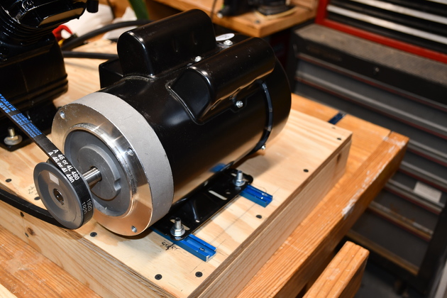
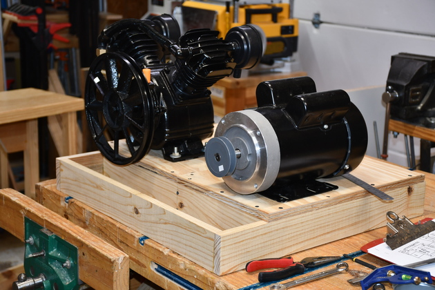
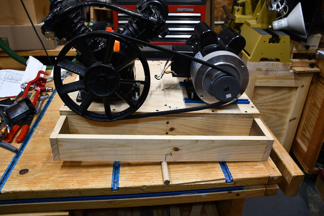
The motor will be beside the pump and both mounted on 3/4" plywood on top of the 1x3" base frame.
The slots in the motor base are xx&uot; long and allow the motor to be moved side to side to tighten the v-belt.
Click for larger pics
Building The Mount
|
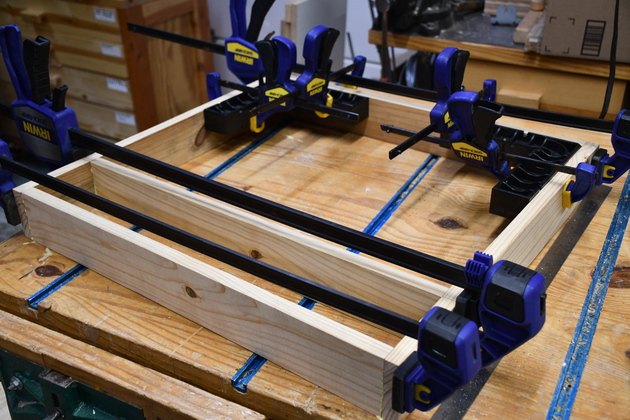
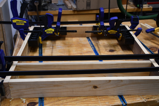
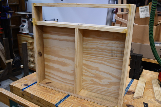
Mount frame being glued.
There are #20 biscuits in each joint.
|
|
Slightly different perspective.
|
|
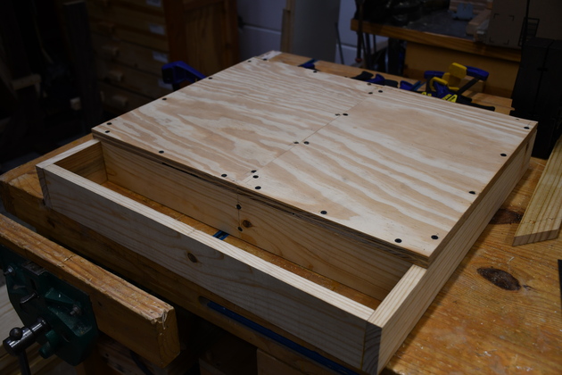
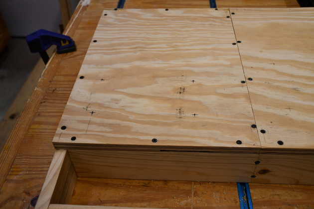
3/4" plywood tops, screwed on.
I didn't have a large enough piece of 3/4" plywood so I used two smaller pieces.
Thats also why I put the extra frame piece in.
|
|
Bottom of mount frame, note the exta support for the two pieces of 3/4" plywood.
|
|
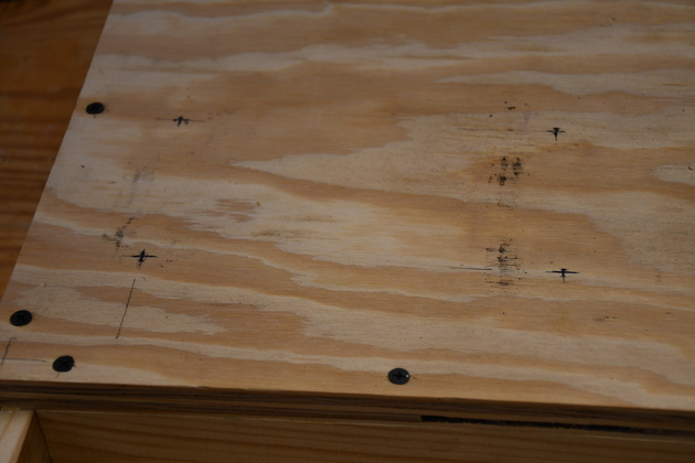
Closer look at plywood top and their screws.
|
Pump Mount
|
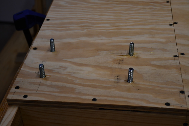
Note the cross marks where the compressor pump's bolt holes will go.
|
|
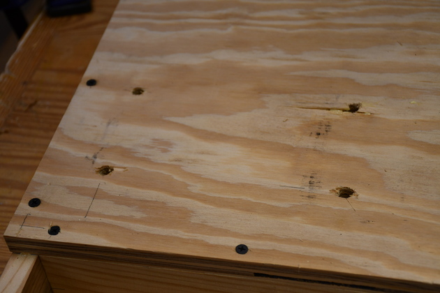
3/8" holes drilled for pump mounting holes.
|
|
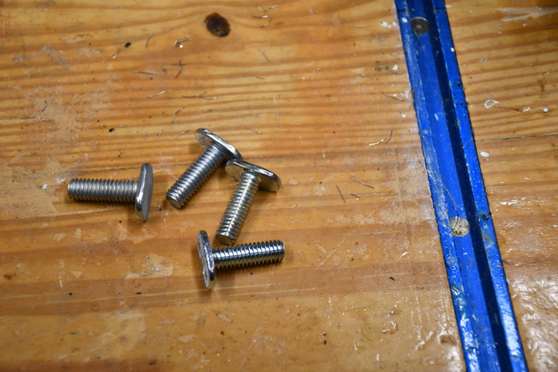
3/8" carriage bolts ready to mount the pump.
|
|
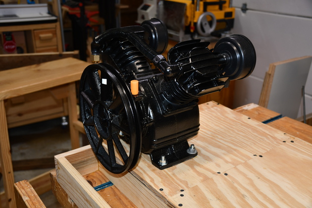
Pump mounted.
|
|
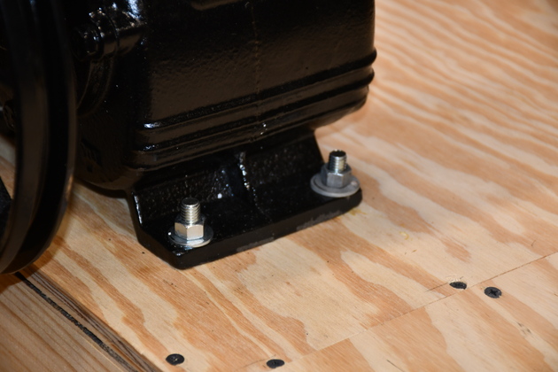
Closer look at pump's mounting 3/8" carriage bolts.
|
Motor Mount
|
|
|
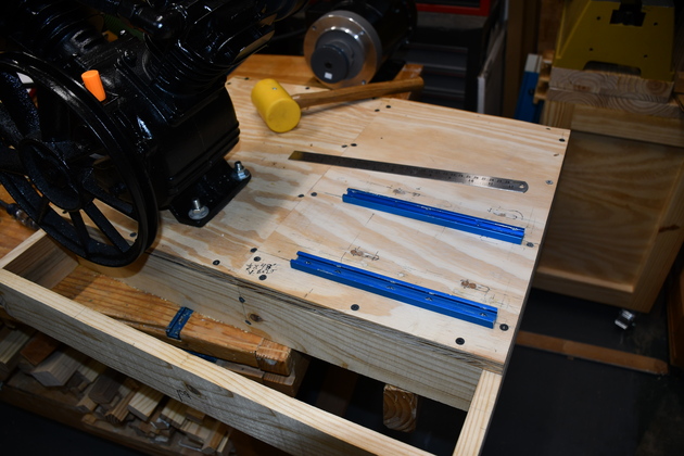
| Figuring out where the motor tee tracks should go.
|
| Several things are important at this stage:
| | Is the motor's sheave aligned with the pump's flywheel?
| | Does the motor slide sideways enough to mount the belt?
| | Does the motor slide sideways enough that the belt is tight?
|
|
|
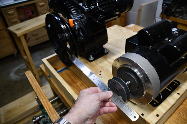
Checking sheave to flywheel alignment.
I measured the distance from sheave's outside edge to the inside of the v-belt groove.
The straight edge is flat against the sheave's front surface.
|
|
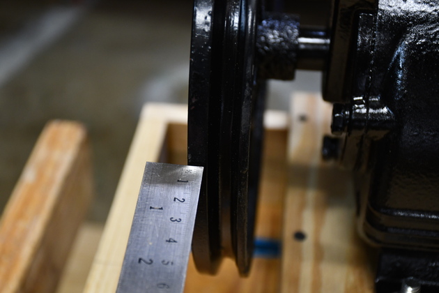
Its hard to see but the inner edge of the straight edge is 1/16" from the inner surface of the flywheel's inner belt surface, the same distance as the sheave's.
|
|
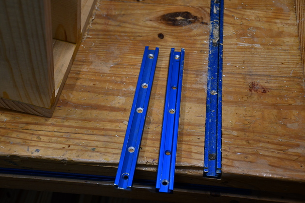
Two 9" long pieces of tee track.
Note: I added extra chamfered mount holes.
|
|
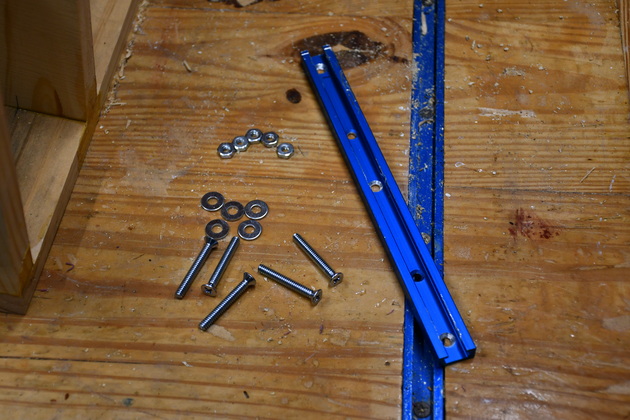
#10-24 bolts, nuts, and washers to hold the tee track down.
Eight of these all told, four for each T-Track.
|
|
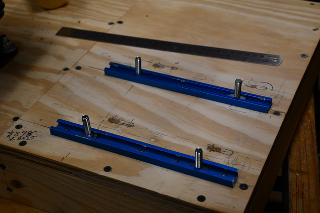
Tee tracks installed
|
|
1" tee bolts to mount motor.
|
|
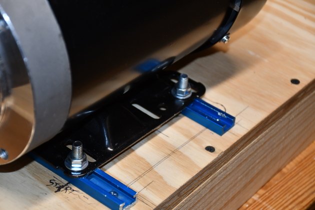
With tee bolts positioned to mount the motor.
|
|
Positioning the tee tracks, needed to allow enough room for the motor to be moved toward the pump so a belt could be installed, then moved to tighten the belt.
Note the extra space allowing for belt stretch.
I had decided to move the motor toward the edge of the mount, then move the sheave back, thus allowing me to line up the sheave and flywheel.
|
|
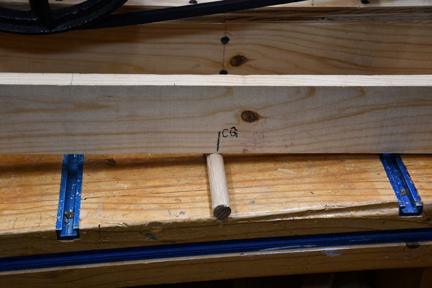
I needed to find the approximate center of gravity to help when attaching the mount to the test stand (and in the attic).
Note the 3/4" dowel under the mount frame.
I rolled the frame back and forth until it balanced, hence the center of gravity.
|
|
Closer look at dowel under the mount frame.
|
|
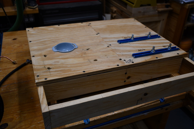
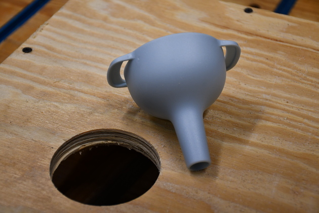
The mount with oil drain funnel installed, ready to paint.
|
|
Clser look at the mounted funnel.
The two holes are two of the compressor pump mounting holes.
I put this in, hopefully, to keep oil off the mount itself.
|
|
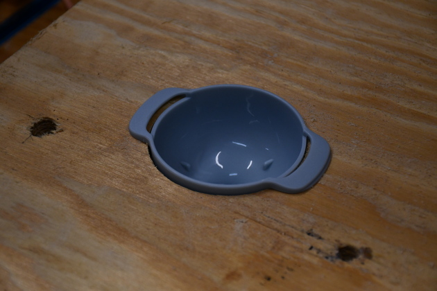
The funnel beside the 3-1/8" hole it fits in.
I bought a set of cheap funnels, one exactly fits the pump's oil filler hole, this is another.
|
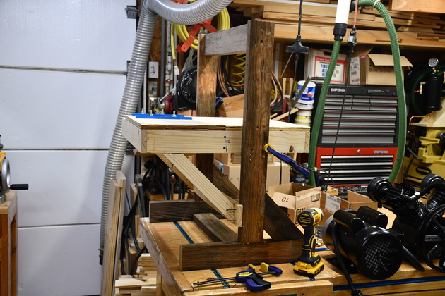
Test Stand
|
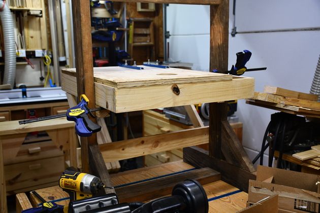
The dark wood test stand, supporting the mount.
The test stand simulates two vertical 2x4s in the shop's attic truss, where the compressor mount base will be installed.
I put this together to be sure I had all the mounting things right.
It allows me to properly support the base and keep every thing level.
Hard t osee with all the clutter, but!
|
|
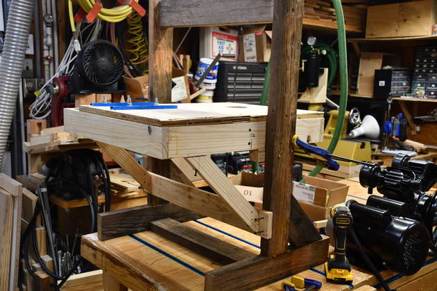
A little closer look.
The screws on the diagonal support are barely screwed in just to hold the base.
|
|
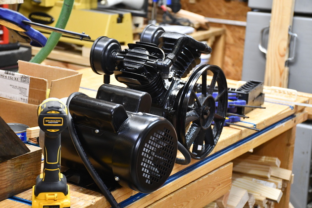
Motor and pump have been unmounted for the trip into the attic.
|
|
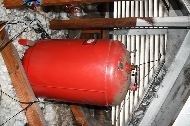
This is the side nearest to the 30 gal. attic air tank.
|
|
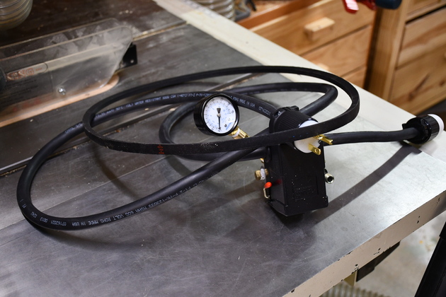
The pressure switch, with 12-3 SO cord and the V-belt ready to go into the attic.
|