|
|
|
| ||||
|
Replacing Jet DC-1100 Blower Motor with DC-1200 Blower Motor
| |||||||
|
|
|
| ||||
|
Replacing Jet DC-1100 Blower Motor with DC-1200 Blower Motor
| |||||||
| Back So Automation | Dc240Switch | New 240V Ckt | Flat Wall Patching |
| Old Blower | New Impeller | New Motor | Src End |
| Dest End | Running Wiring | Blower Install | It Runs |
A few years ago I moved the Jet-DC1100 blower to the ceiling and added a cyclone separator. Then in 2020, I automated the entire system.
New Motor
The blower motor (old Jet DC-1100) in my 6" dust collector, is getting very old and even twice has tripped the dedicated 20 Amp breaker (both times the planer was working).
I bought the DC-1100 about 15 or 16 years ago, and it has been reqularly used ever since.
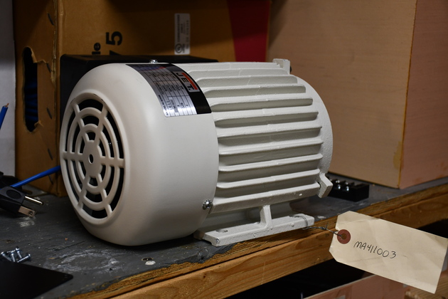
I decided recently, to replace and upgrade the blower motor to a MA411003 and impeller.
Turns out the Jet DC-1100 and DC-1200 use the same parts for the blower housing and motor supports, but instead of the 1-1/2HP 120 Volt motor the DC-1200 uses a 2HP 240 Volt motor and slightly larger impeller.
I had already bought a DC-1200 impeller, thinking I would replace the DC-1100 impeller, but when the old Jet motor started tripping the breaker, I felt it was time to replace both.
I measured the current draw by the DC-1100 motor at 9.3 Amps, shouldn't be a problem, but it trips the circuit breaker occasionally.
I don't have any excessive voltage drop in any segment feeding the blower, and a different breaker didn't solve the problem.
So I decided it must be time, and bought a new DC-1200 motor from MMtoolparts.com and got after it.
New Motor Pics.
Physical Replacement
One of the more difficult parts of replacing the blower motor is: getting the blower down off the wall, it weighs about 60 Lbs. and is bolted to a wooden frame almost touching the ceiling.
I have to move the bandsaw, table saw, remove hanging dust hoses, dust bin, cyclone, unbolt and lower the motor, and move to the work bench.
After I have the blower assembly on the bench, I have to pull the cover, then the impeller, remove the housing, remove the motor from it's steel mounting frame.
Here are some pics of the original install.
The motor, it's mount, and the impeller with housing weighs about 55#.
When I installed it I used an old boat trailer wench, which I still have, bolted to the wall and a hoist bar bolted above the blower motor housing.
Betty and I still remember installing the blower, she cranked the wench while I guided the blower up then bolted it to the wooden mount I had already bolted to the wall.
Thank goodness I made all the Dust Automation stuff modular with plugs, so I can unplug anything I need to remove (or replace).
We will reverse the process to get the old DC1100 blower down.
This will be the 3rd time I have winched the blower up to the ceiling.
New 240 Volt Circuit
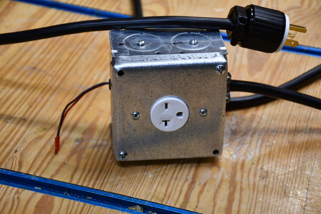
In the United States, 240 Volt 20 Amp circuit requires NEMA 6-20P plugs and NEMA 6-20R receptacles.
BTW, you can get the receptacles a little cheaper than the Leviton.
The old DC-1100 blower is 120V, the new DC-1200 blower requires 240V 20A, so I'll have to run a new circuit to it.
The blower is currently on the 'Shop East' circuit.
The last time I was in the box was last winter (2020) to install a 240V circuit for the mini-split.
But, the breaker box is full, so what to do?
Noting, my ancient Gould box is a type HOM.
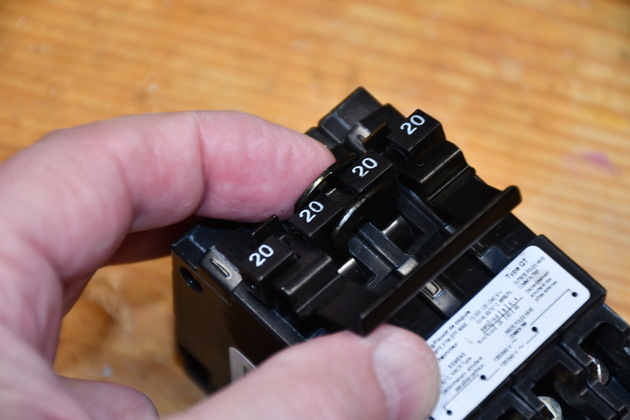
I found quad breakers at Amazon that will give me a 240 volt, single phase, circuit and two 20 Amp 120 Volt circuits.
Please take a look at pics for New 240 Volt Circuit.
Running wiring through the walls
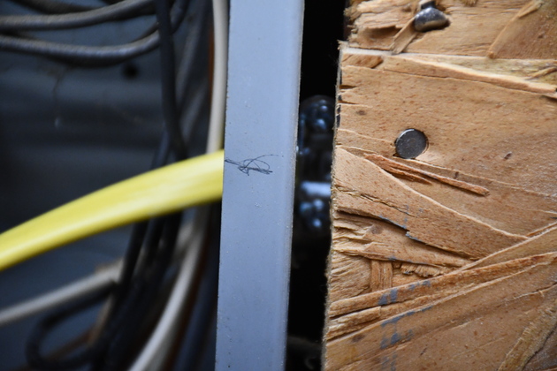
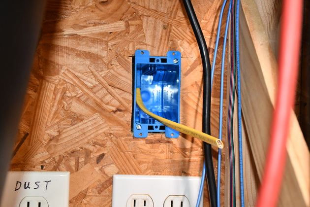
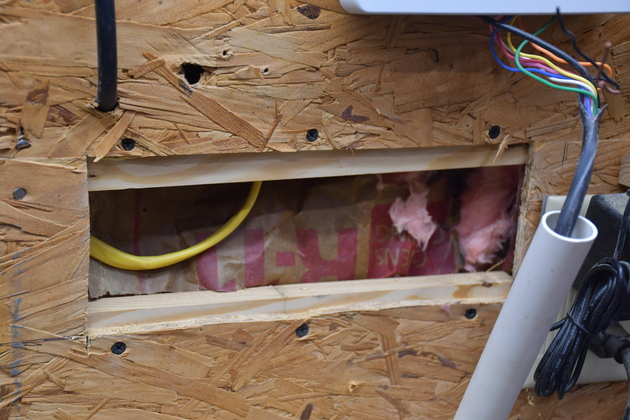
When I run a new circuit in the shop I cut access holes in the paneling so I can bore holes in the plate or fireblock and route the wire down to the breaker box or receptacle hole.
One of the concerns I've always had when cutting through existing paneling is not cutting into a wire or pipe behind the paneling.
House wiring is normally stapled to the 4" side of the studs, so if you stay a small distance from the studs you "shouldn't encounter" any wiring, unless somebody didn't follow the rules.
There are tools to find wiring behind walls.
To help visualize this take a look at how house walls are framed.
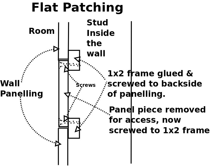
Heres how I
Flat Patch a wall.
I cut the access holes with a Fein Multimaster so I can control the depth of cut, and don't saw into anything below the paneling.
In home construction, wires and plumbing are not normally placed against the paneling or sheetrock.
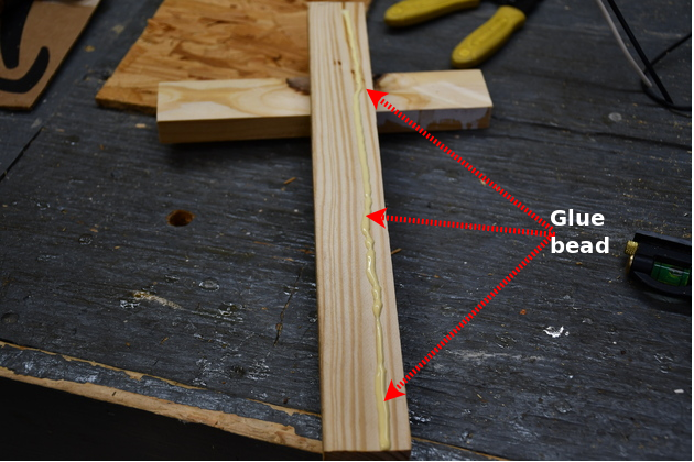
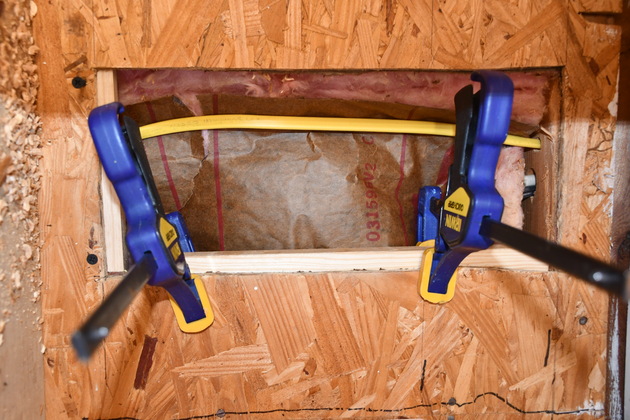
I glue a small 1x2 wooden frame to the back side of the paneling so it overlaps the hole I just cut.
When I'm ready to cover the hole, I screw the original paneling cut-out to the 1x2 frame.
See the Panel Flat Patching pics.
This same procedure works for sheetrock!
You just have to do a little texturing (or spackeling) and touch up paint after you finish.
It Runs
Well, I reinstalled the blower, cyclone, and dust bin, reconnected all the power, sensor, and vacuum connections.
Did a little checking, turned on the sander, and voilla, it runs, only much better.
There is a noticable increase in vacuum, and the motor sounds a little different (deeper, more serious sound).
|
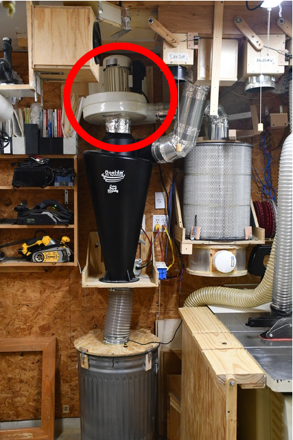
| Replacing the blower's motor and impeller. The cyclone stack: The blower on top, cyclone, and dust bin on bottom. To replace the blower (red circle), everything will need to be removed from the blower (on top) to the dust bin (on bottom) and all dust hoses disconnected. The blower (motor, impeller, and housing) weighs about 60Lbs. so I use a boat winch near the floor, to raise and lower it to the mount point near the ceiling. Please see the Blower Install page. I have already moved the bandsaw and 2 of the dust hoses, the table saw, on right, will also need to move. |
|
The old impeller still on the DC-1100 1-1/2HP motor. |
|
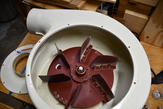
New impeller with new motor, both for Jet DC-1200. Note there are no "puller holes" in the hub. |
|
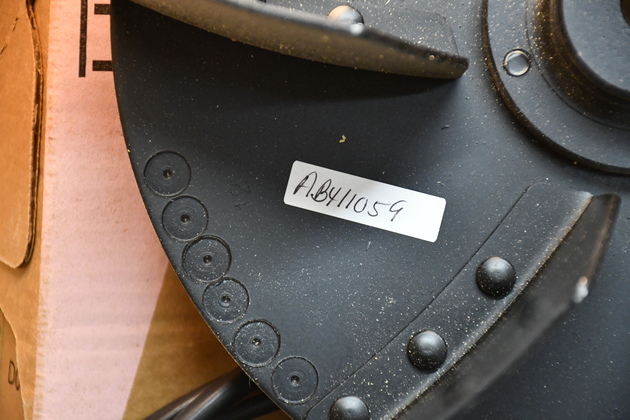
Impeller 12" (Jet AB411059) for the DC-1200. Mmtoolparts.com has this impeller. |
|
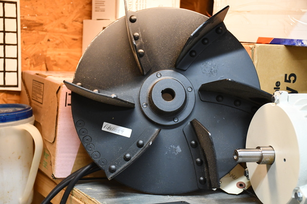
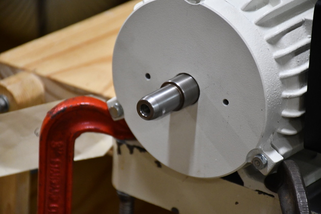
The new 2HP 240V motor (Jet MA411003). I ordered this motor from mmtoolparts.com. |
|
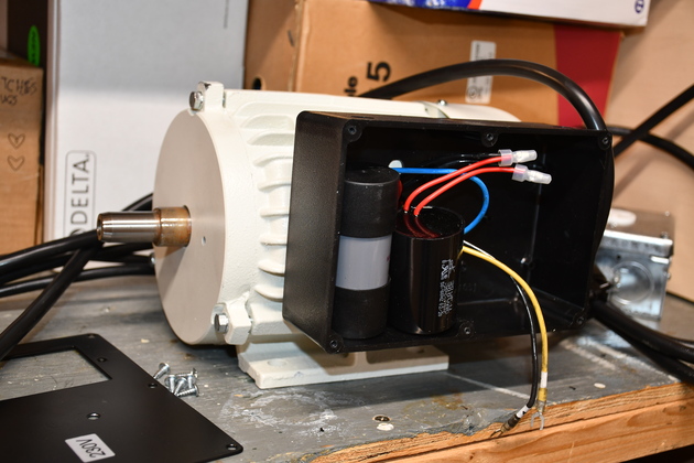
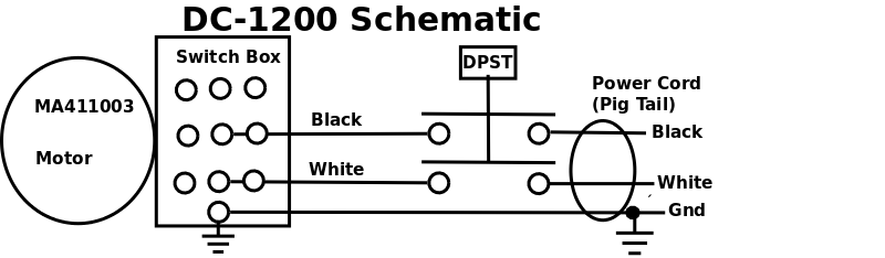
I have the switch box lid off, the start and run capacitors are both floating. I'll need a strain relief for the pigtail. I'm purchasing a push button DPST switch for $12.07 (71008) for this motor, it has similar specs and dimensions as the Jet switch (994542). I did have to wallow the two munting holes an 1-1/2 mm on each side to get it to match Jet's mounting holes. BTW: the same switch is used on both the Jet DC-1100 and DC-1200. PowerTec was nice enough to provide a dimensional drawing and schematic, so it is easy to match to the Jet switch box. This switch will be more for connections and to plug the hole in the lid, since I'm using the hi-power 240V SSR, it only needs to turn ON once. The Jet manual for the DC-1200 shows black & white wires to the motor, these appear black and pale yellow, which doesn't matter for this circuit. |
|
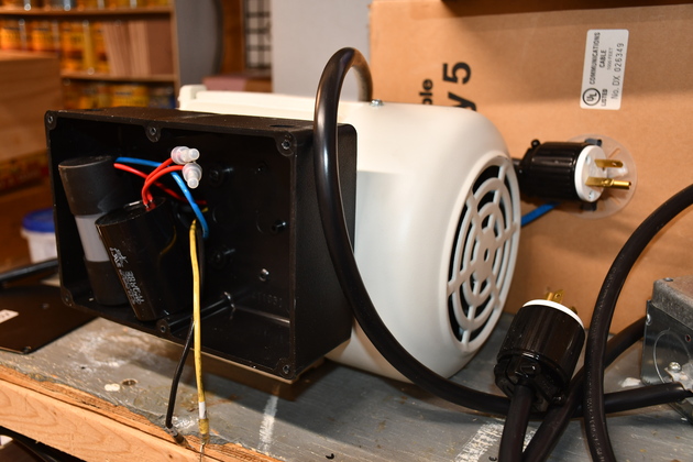
A little different angle. You can see the fan cover and inside the switch box. |
|
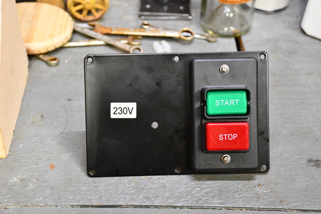
Motor switch mounted on the motor's panel. I bought this switch from Amazon for $12.07, thinking It would exactly fit the panel, but I had to wallow the mounting holes in the switch and bezel about 2mm on each side. Remember, in my case, it only needs to turn on once, it mostly acts as a barrier strip (connection block). However, I did turn it on and off a number of times during testing. The $12.07 compared to the Jet Switch (Jet #994542) $68.36. |
|
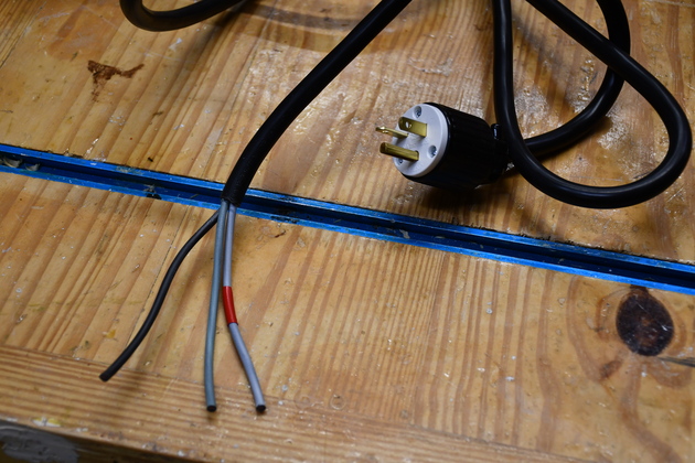
Power pig tail for the new motor. Note the red tape on the neutral wire (lighter gray). |
|
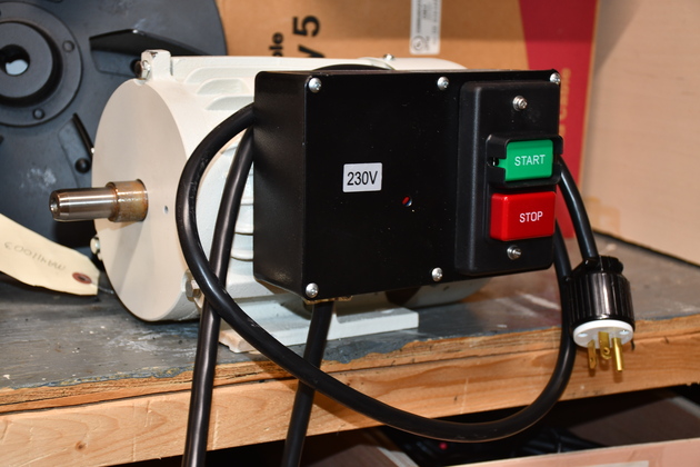
New motor with switch and power pig tail installed, ready to mount. |
|
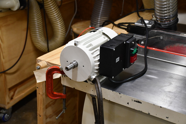
New motor plugged into new circuit, running.
|
|
It really is turning. |
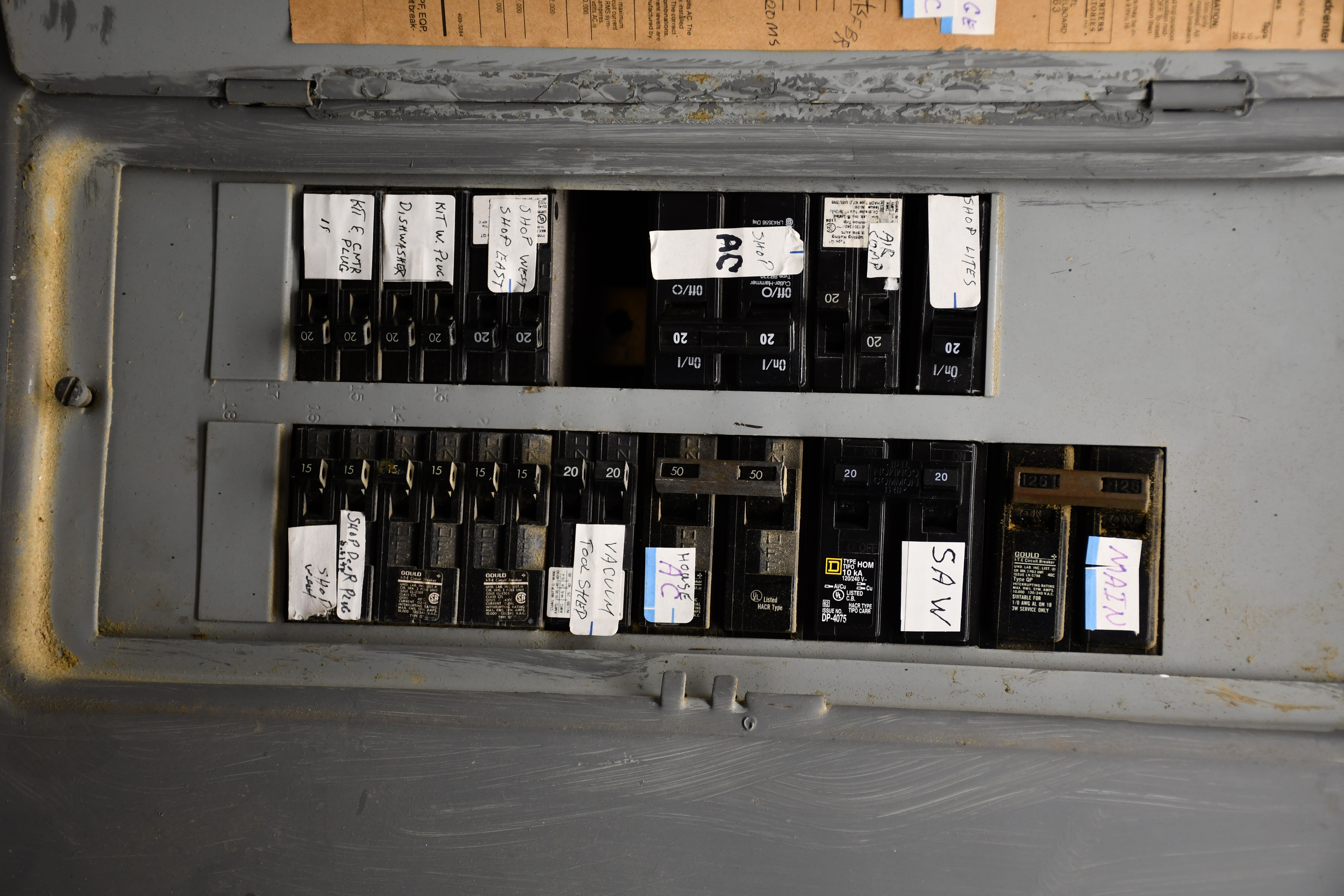
I'll need another 240 Volt, 20 Amp circuit for the new 2HP motor. This involves running a 12-2 w Gnd diagonally across the shop from east wall to west wall, then down inside the walls to breaker box on the east and new 240V wall plug on the west.. Since my breaker box is full, I bought a new Square-D Quad Breaker to replace one of the other dual 240 Volt breakers. This breaker has 1 pair of ganged 20 amp breakers and 2 individual 20 amp breakers in a dual package, with yokes on the center pair and outer pair. I currently have a single 120Volt 20 amp breaker for shop lights and another for the air compressor. These two single breakers take up two standard slots, I can use the Square-D quad in this dual position with the two individual 20 Amp breakers replacing the 2 single circuits above and the ganged breakers for the new 240 Volt circuit.

| The new 240V circuit (in In Red) upper right, will come from the breaker box on the east wall to the junction box in the attic, and from there to the new 240 receptacle on the west wall. Pale pink circuits were added earlier. Click for larger pic. |
Running the Wire
Here is a page to help visualize running a circuit through the wall.
There isn't much room in my attic, like most tract houses, the roof is about 6/12 pitch with trusses, which means there isn't much room in the attic especially out nrear the outside walls.
Both the breaker box and new receptacle are in outside walls, bummer!
I ran the new circuit in two pieces, with a junction box in the middle, so I wouldn't have to crawl out to the plate to run the Romex down through the plate on either end.
|
|
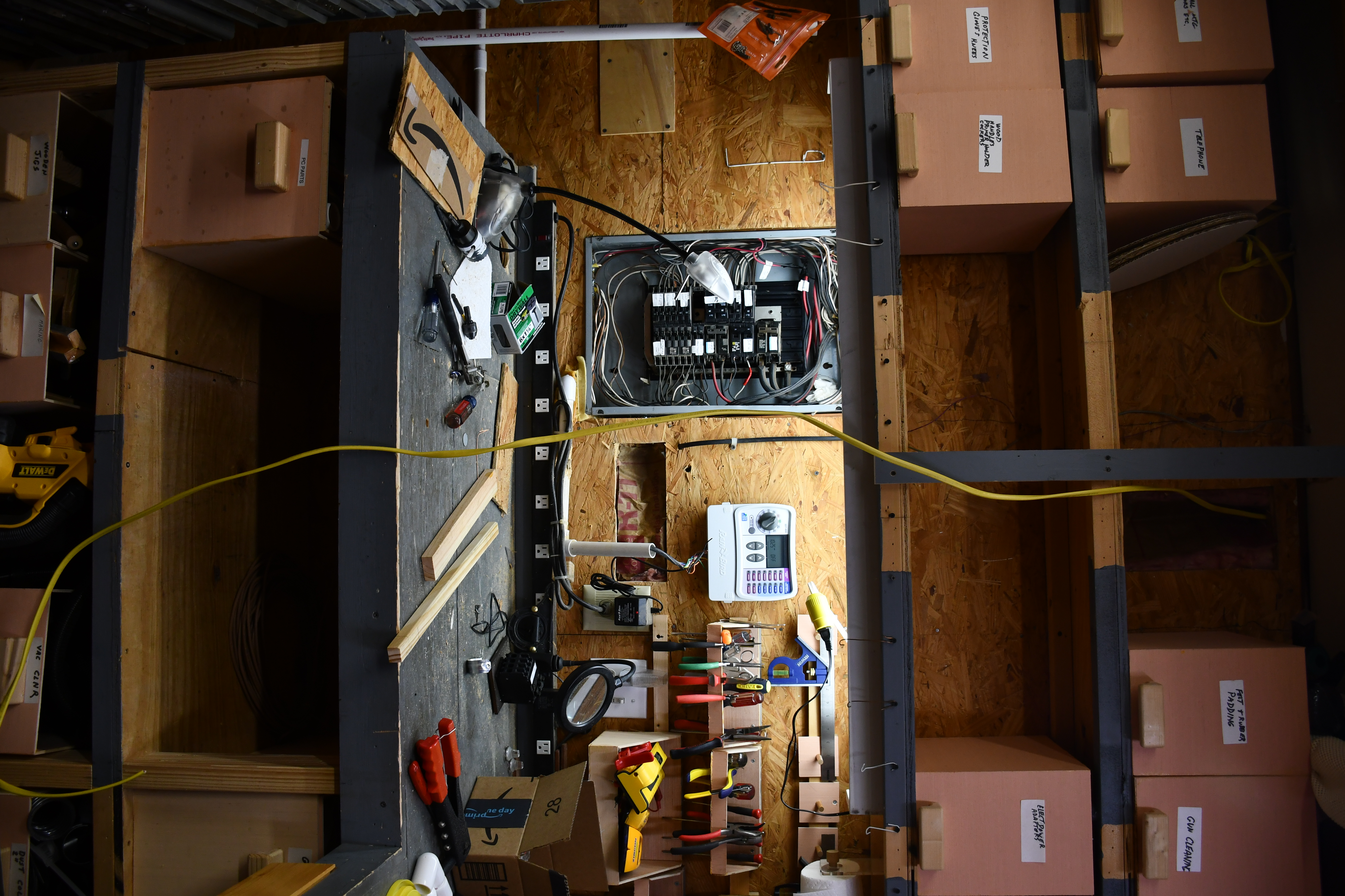
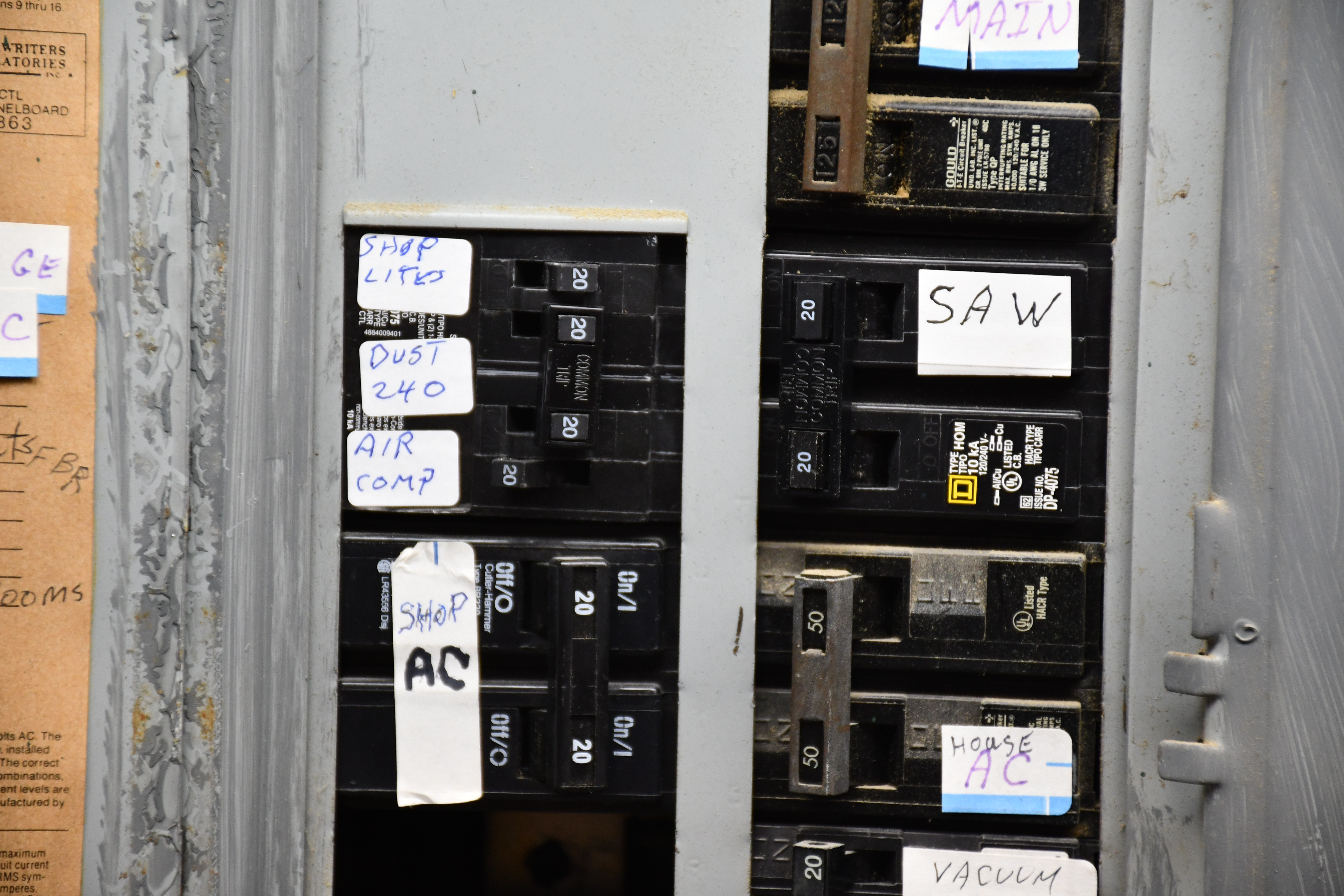
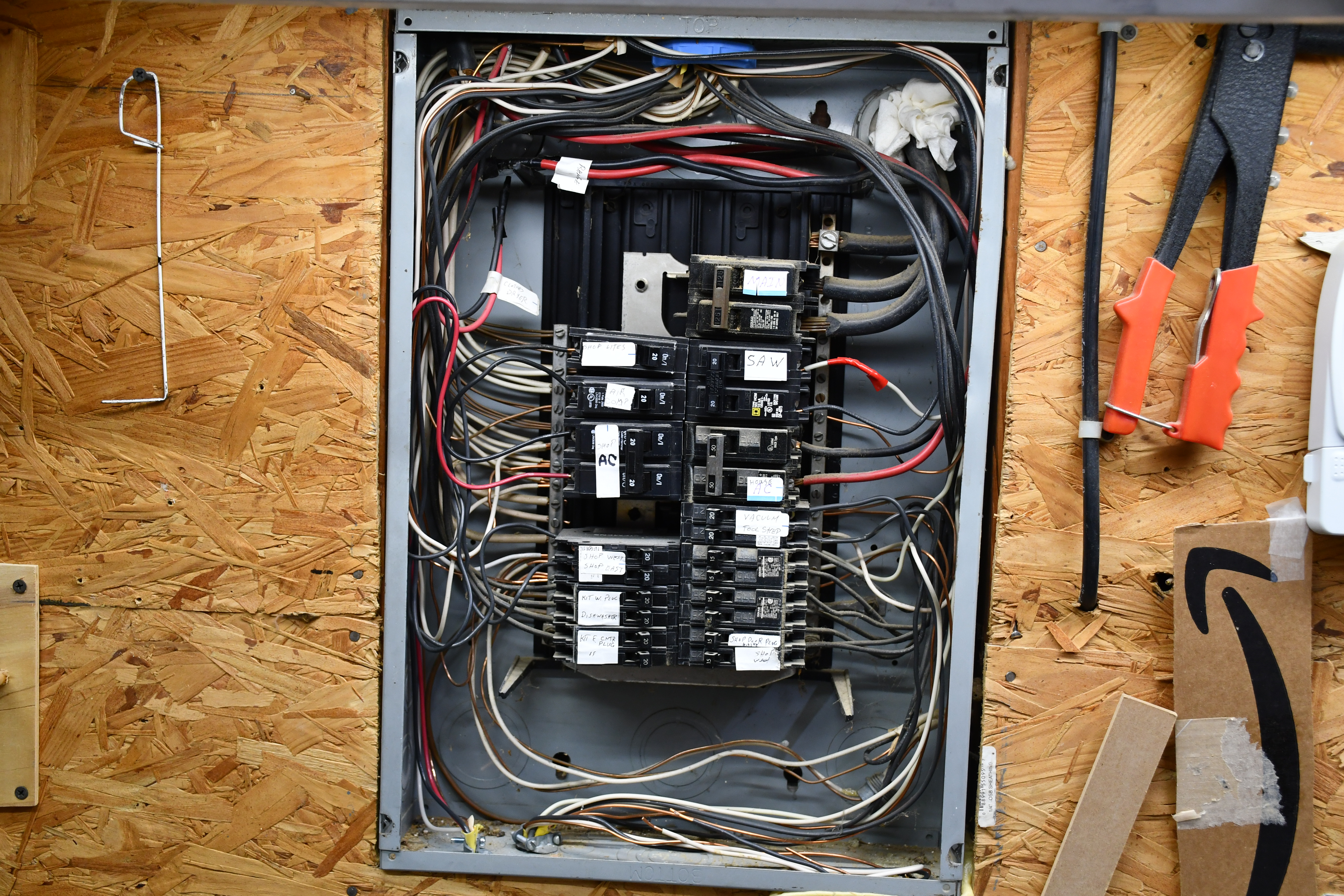
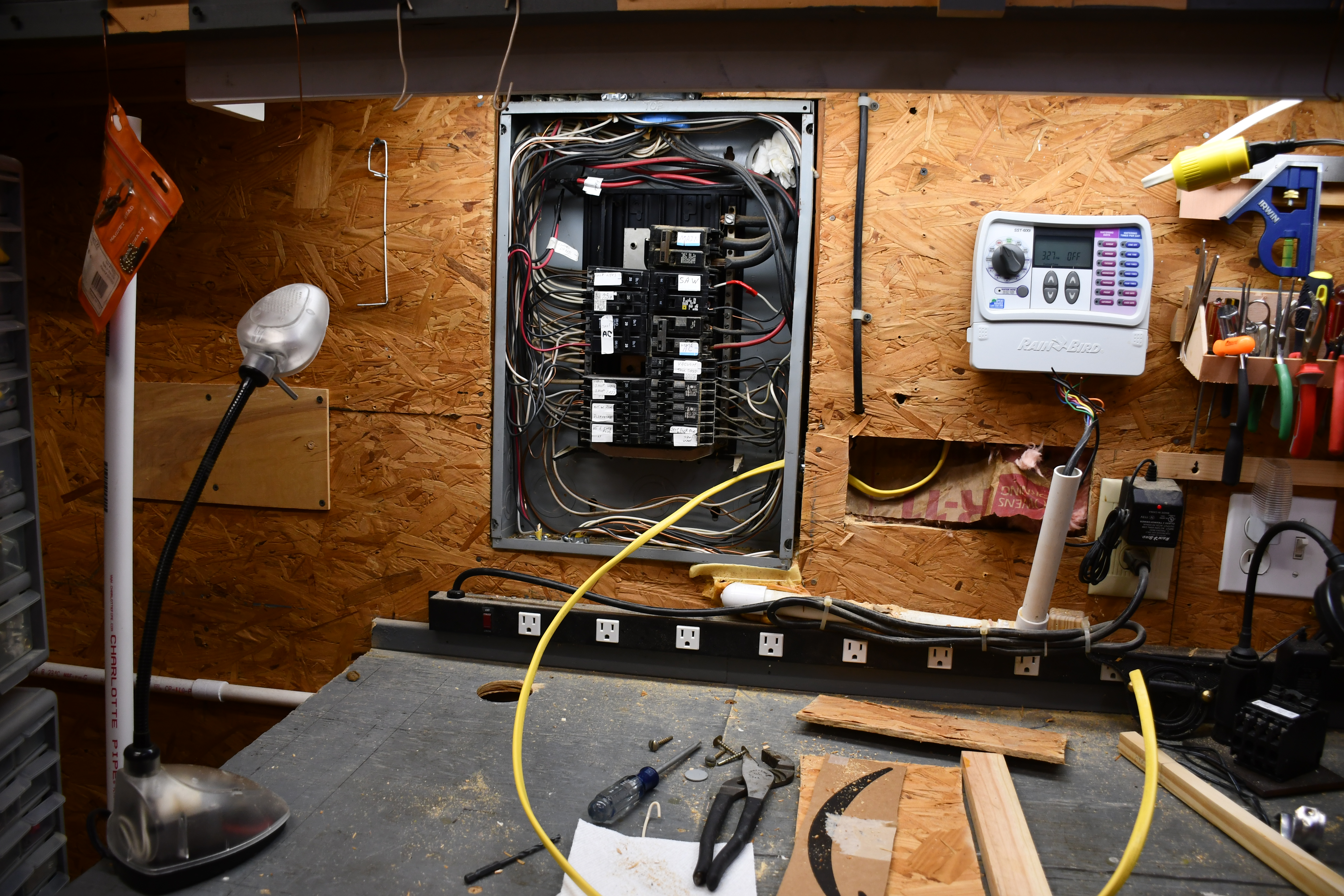
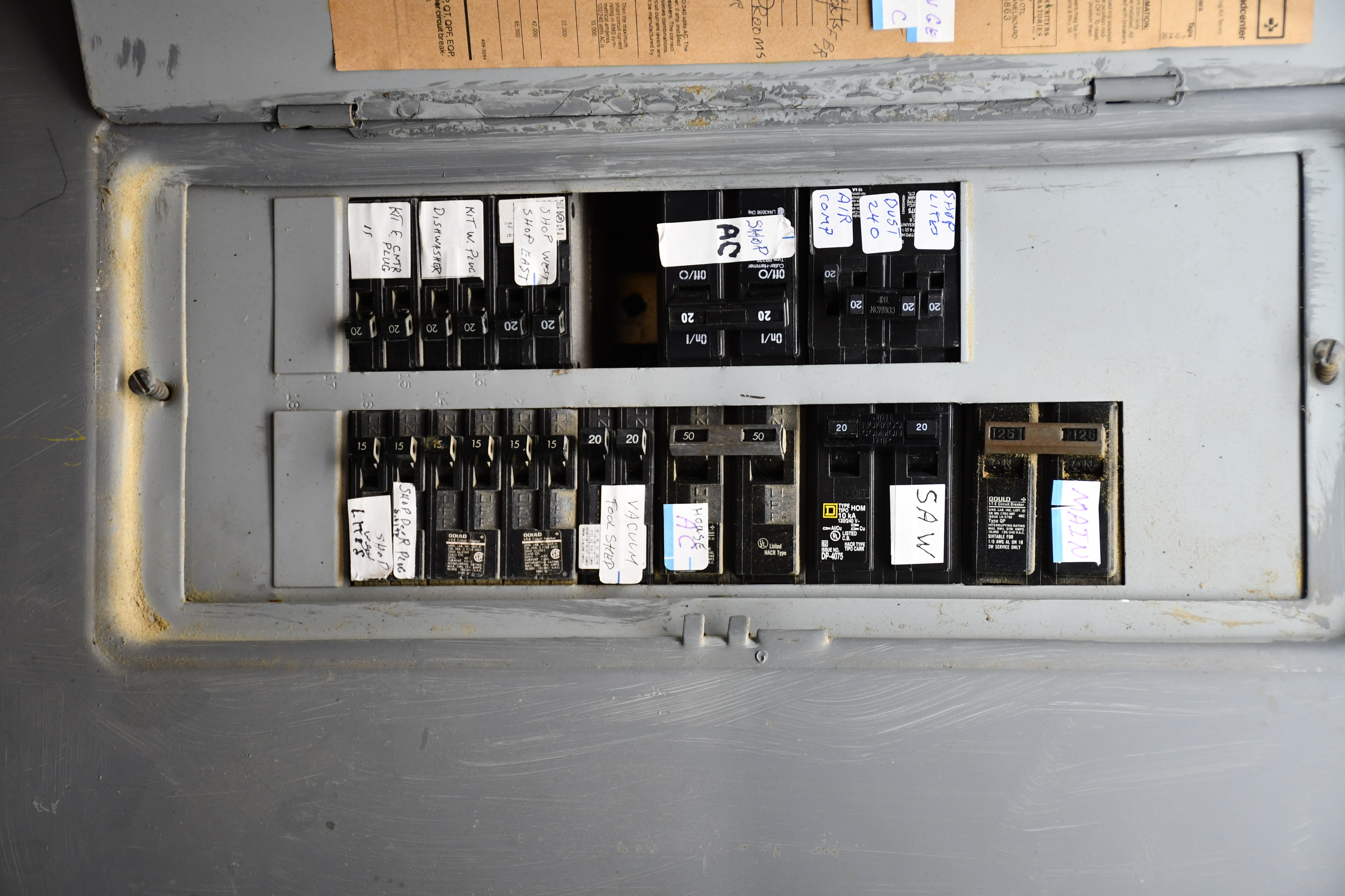
Ancient Gould breaker box, 39 years old, and it was cheap initially.
I frequently check temperature on each breaker.
Empty slot is an unusable double (240V) slot below the 'Shop AC' breakers, I noticed lights blinking and traced it to an old Gould breaker that was arcing over because it didn't make good contact with the hot buss bar tab below.
Now the buss bar tab,s in that position, were damaged by the arcing and don't make good contact with any breaker.
I will use the new quad breaker to replace the 'SAW' breakers and yield a second 240 volt circuit for the new DC blower.
Click image to get HD pic, then click again to zoom. |
|
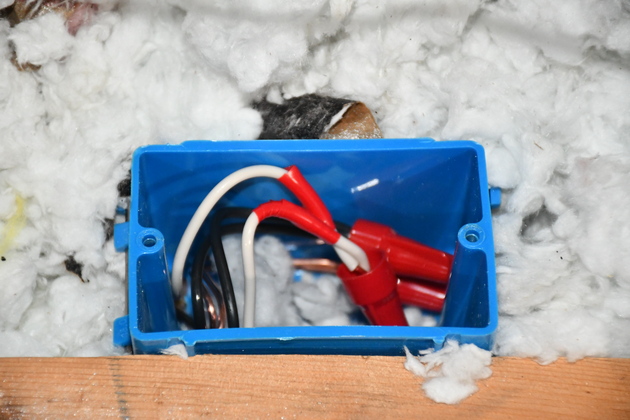
Box open (older pic).
Note the white wire to one phase of the Saw 240 volt dual breaker, it has red electrical tape to indicate its hot.
BTW: On the Left: Note the hanging white piece of coathanger, bent with a hook and handle, Thats what I used to clean out blast gates before I modernized my dust collection. Click image to get HD pic, then click again to zoom. |
|
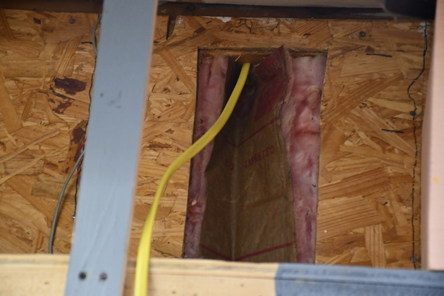
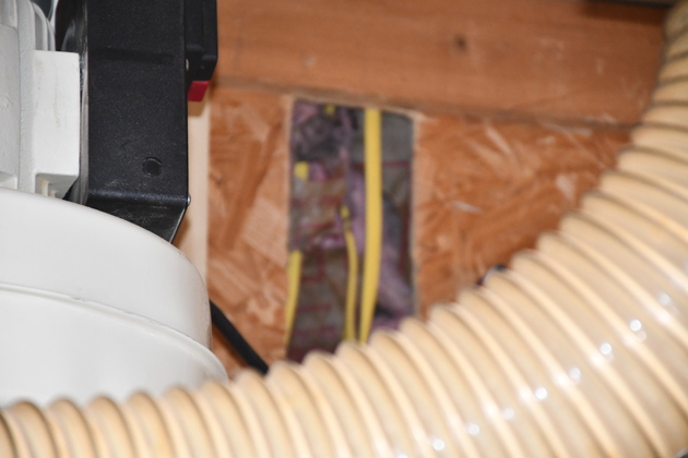
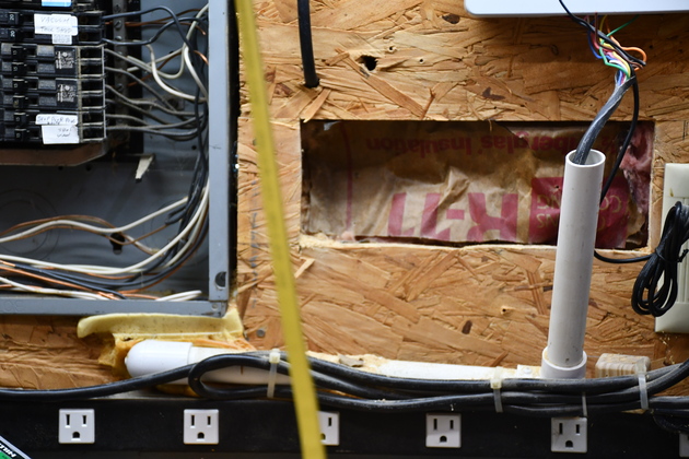
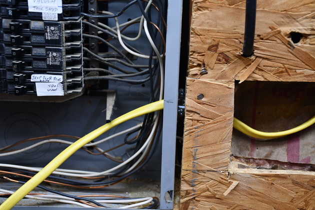
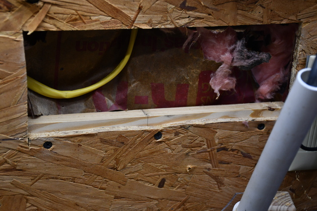
2nd hole beside the breaker box, and directly below the upper hole below the plate. You can see the blurry yellow Romex in the foreground. |
|
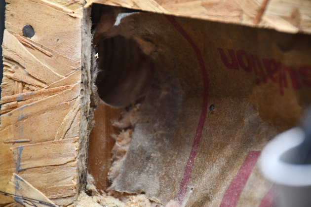
I used a hole saw to drill this hole through the stud in line with the knockout I had chosen. |
|
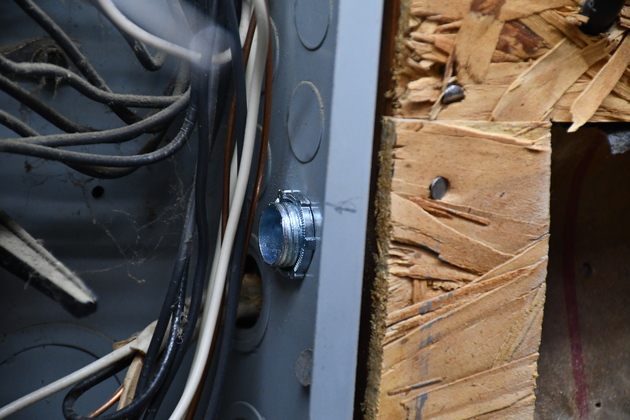
I knocked out a knockout and screwed this cable clamp into the hole. You can see the breaker box has a lot of knockouts for just this reason. |
|
I fed the wire down from the top hole (below the plate) to the second hole, then through the drilled hole and the cable clamp, into the breaker box. |
 Click for HD pic |
The breaker box with the new Romex (Click for HD pic). I've noticed the custom, when wiring a house, is to leave wires inside the breaker box very long so they can be routed around the edge of the box, well away from the acutal breakers. |
|
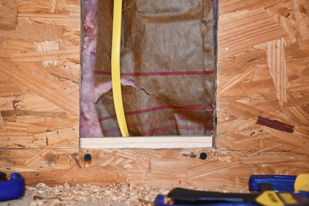
Lower cut-out, the bottom frame piece is installed. |
|
Now the upper piece is installed. Next I'll glue/screw the end frame pieces. |
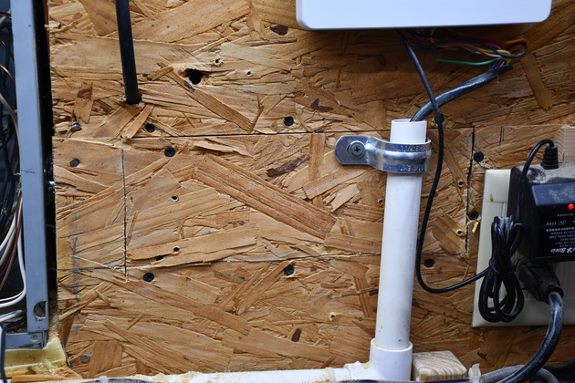
|
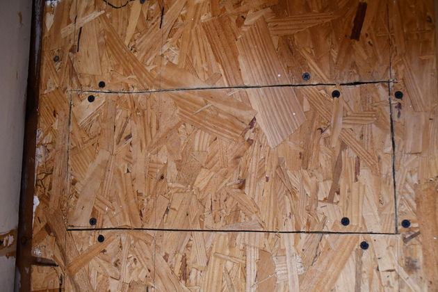
The lower cut-out installed. The cut-outs are not glued, just screwed, in case I ever need to get into this wall again. |
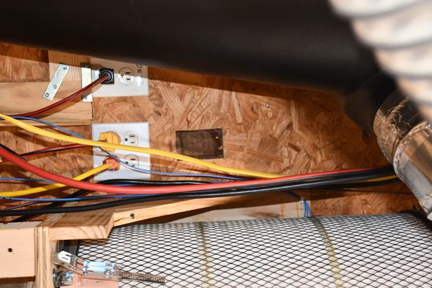
|
The hole for the 240 Volt receptacle with the 12-2 w Gnd Romex. The black cone on the left is the 6" cyclone. |
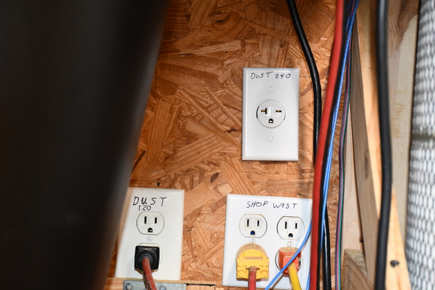
|
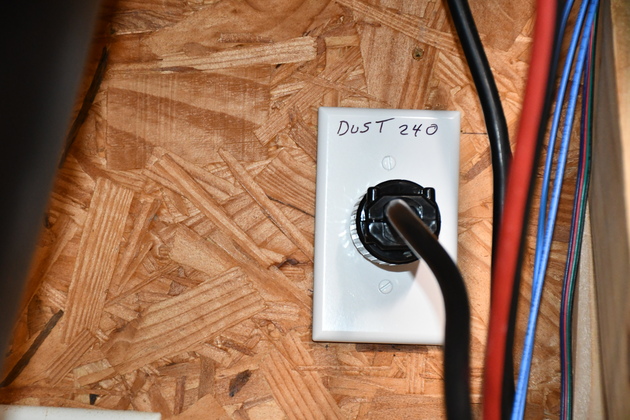
240V 20Amp receptacle terminated and ready to power up. |
|
Junction box in the attic. Remember, I pushed two pieces of Romex up into the attic from each side of the shop. This is where the two tie together. |
|
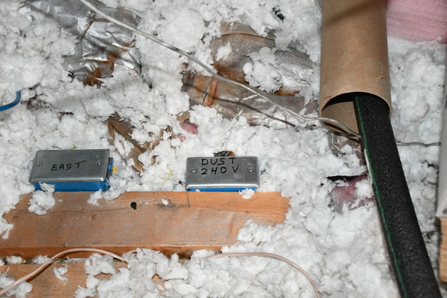
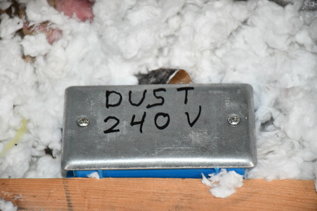
Closer look at my fancy label. I try to label things like this when I add circuits to the house so someone else can tell whats going on. |
|
All the breakers in the box as of 08/02/21. Click for HD pic. |
|
Motor plugged into new circuit. |

|