| 
| 
| 
|
|
Shop MiniSplit AC
| |||
|
|
|
|
|
|
Shop MiniSplit AC
| |||
| Back To HeatCool | Unit Info | Old AC Removal | New Unit Arrival |
| Inside Mount | Outside Mount | Power | Flare Nut Torque |
| Torquing | Vacuuming | Finished | Thermostat |
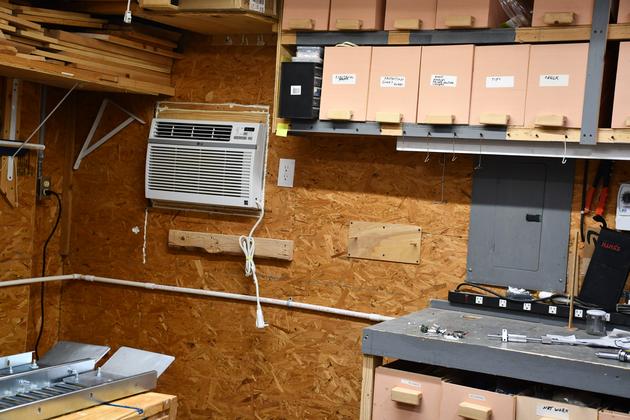
In 2018 the old Samsung AC in the shop died (RIP). I went to Consumer Reports and found the best replacement window AC I could, which turned out to be an LG. I had heard some bad stories about LG but Consumer Reports is a good source for info on these things. The Samsung was a 18000 BTU (1-1/2 Ton) using 240V, the LG was a 12,000 BTU (1 Ton) using 120V. The Samsung lasted about 14 years. The LG's first year I noticed the water coming out the condensation drain was very rusty, leaving rust streaks wherever it ran. This is not a good thing, I don't think this LG is nearly as good as the Samsung. One other note, the LG, being a 12k BTU system doesn't blow as hard as the Samsung, hence I had to use a small fan to circulate the air. In 2019 the plastic condensation connecter had failed and water was leaking straight down on my BBQ grill cover, in addition, the rust in the water was very bad and had stained the grill cover and the cement under it badly. In late 2020, during the Covid-19 pandemic, the LG was still cooling but the rust stains outside had gotten even worse.
In the fall of 2020 and after the 6" DC automation project was complete, I decided to start planning my next shop AC.
Mini split AC appealed to me, and since they cool and heat and are very effecient (20 SEER), I can retire the 57+ year old Dearborn stove, (it still has the original radiants BTW).
The MrCool 18000 BTU DIY (A-18-HP-230B) caught my eye, but after reading a lot of customer feedback about bad customer support on Amazon, I searched and found the Senville 18000 BTU.
It has a 20 SEER rating, it costs about $1200, but it is not quite DIY, but easily done, with a little experience, a vacuum pump, and a vacuum guage.
I found a pretty good video on YouTube.com by Doublewide6 about install this exact AC.
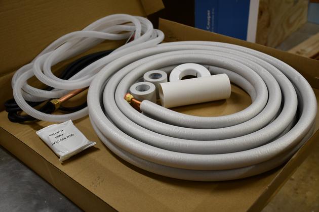
The Senville comes with the refrigerant line set, the charge is in the outside unit so you need to connect the lines and vacuum down the system before opening the charged line.
The MiniSplit is a Senville Aura series, model: SENA/18HF/OZ.
A lot of mini splits use wireless and can be controlled by a smart phone, but, since I'm not a fan of smart phones (worked in network security 10 years) I'm thinking the hand remote should be sufficient.
Although, there are a few compatible WiFi thermostats that allow remote control of a minisplit via a desktop.
The old Samsung 18000 BTU AC had required 240V AC at 20Amps which I then rewired for 120V @ 20Amps, for the LG, so I'll need to return to the 240V circuit but it won't have plug inside, it'll be wired directly into the disconnect outside.
The only electrical problems I have had in this house, the former owner was a telephone repairman, and used gobs of black plastic electrical tape (no wire nuts) and used 12 AWG wire on 15 Amp. circuits.
I'm not an professional electrician, just a homeowner, but, long long ago in a galaxy far away, I was an electical engineer and understand the National Electrical Code, and intend to obey it.
The Senville needs 240V single phase AC at 20Amps, all power is fed to the ouside unit which, in turn, feeds the inside unit.
I'll need to set a disconnect outside and run 20Amp 240Volt power to it from the breaker box which is on the other side of this same wall.
Since the circuit is single phase 240V @ 20 Amps, I ran it with 12-2 with ground, so I'll mark the white wire with red tape on both ends.
Most folks houses are supplied with two phases of 120 Volt AC, but the two phases are 180° out of phase so if you measure between the two phases you see 240 Volts, this is what appliances refer to as single (or split) phase 240 Volt.
BTW, 240V single phase means I don't need a return line (but I'll run one in case something changes in the future), just the two individual 120V phases with ground.
Most modern full house ACs need at least 30Amps, but this mini split only needs a 20 Amp circuit so I to got a larger disconnect than I needed and put 20A fuses in it.
I bought a Siemens WF2030 30 - 60 Amp disconnect, wall mount box, and when it arrived, I determined it used Femule (??) 15mm x 50mm cartridge fuses, so I ordered two 20 Amp 250Volt fuses for it.
I also needed a weather proof "whip" to carry power from the disconnect to the outside unit.
I also ordered an outside unit support, a plastic cover set for the lines, and NylogBlue flare sealer.
It works!
After having a mishap when I opened the valve on the outside unit to let R410a into the system, the lineset's flare nut on the liquid line behind the inside unit, blew off, thus I lost all Puron.
I had to get a HVAC tech to charge the system and now it works perfectly.
BTW, this thing is interesting to watch while it works, it frequently makes changes in the large deflector door on the lower side of the air handler, and of course it changes air speed.
|
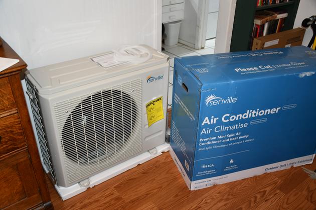
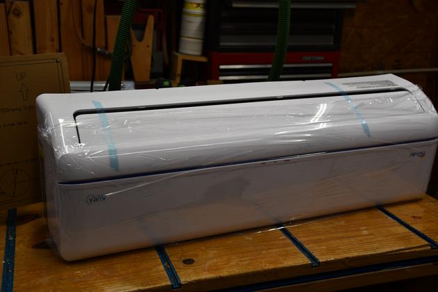
Outside unit, unboxed in our den. |
|
Line set box contents. You can see the drain hose and interconnect cord(left), line set (right) |
|
Inside unit unboxed, note it is upside down. |
|
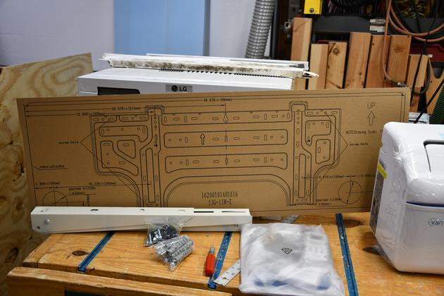
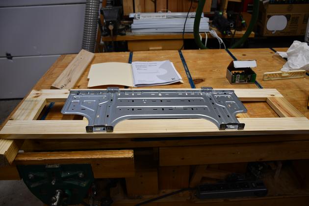
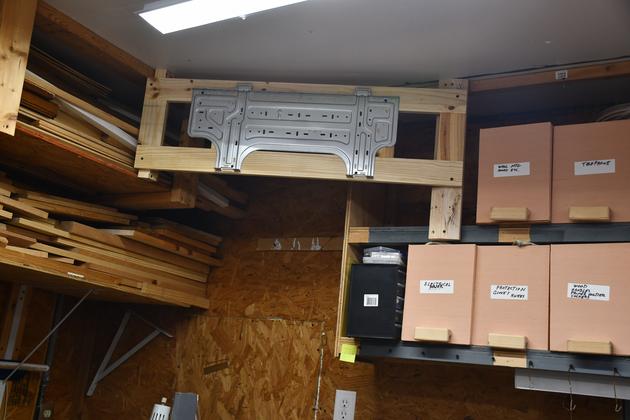
The inside unit mounting plate template. Also note the outside unit support, folded up on the bench. And the old AC behind the template. |
|
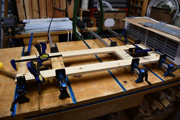
1x3 inside unit panel being glued, there are #20 biscuits in each joint.
The panel is made from 1x3s sawed from a 2x8 Southern Yellow Pine, one of the strongest pines around.
|
|
Inside unit back plate attached to the inside unit panel. |
|
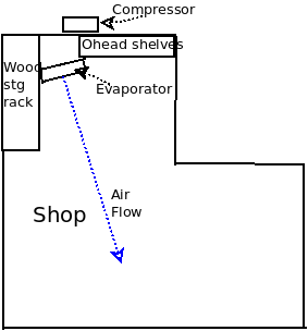
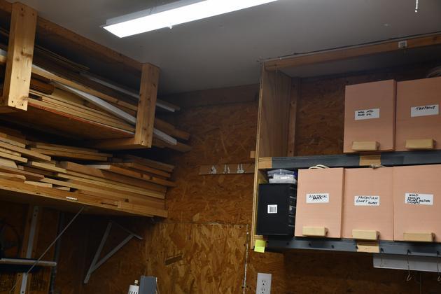
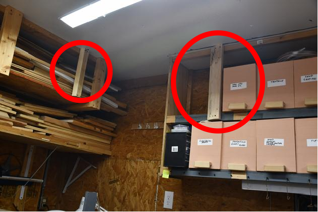
The inside unit support panel will be mounted, at an angle, from the top row of storage boxes (right) to the wood storage rack (left). I want the inside unit unit pointing at a slight angle to the room, so I'll mount it on a frame which will sit at a 20° angle, hopefully blowing air across the room and into the 'L' (ell). |
|
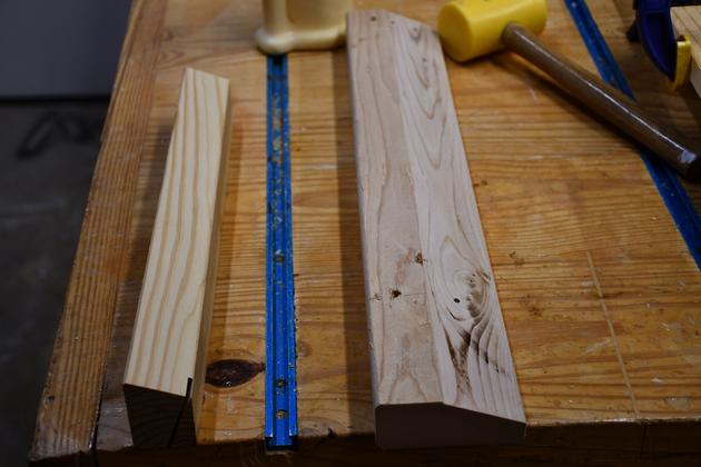
These end supports for each end of the inside unit panel, note the 20° sawed bevels. |
|
I have attached the end supports (Red Cirlces) for the inside unit panel. |
|
Inside unit panel and plate mounted. You can see the slight angle (20°). I still need to cut a hole in the panel for the lineset, cable, and drain. |
|
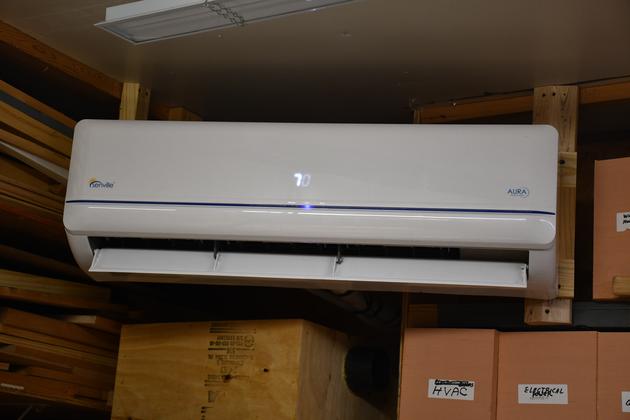
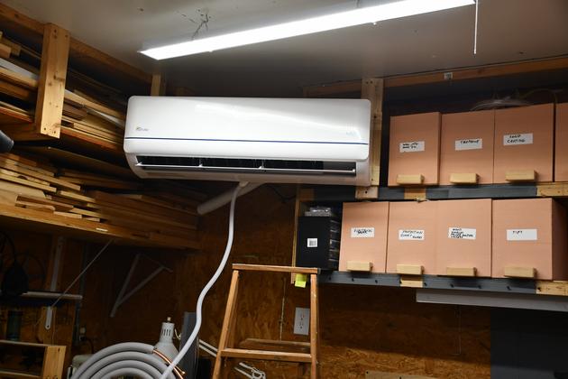
Inside unit installed. |
|
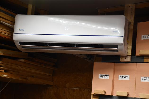
Closer look at the inside unit. You can tell its running since the wind deflector at the bottom is partially open (its close when the unit is off). You can very faintly see the 71° displayed in the center of the unit. |
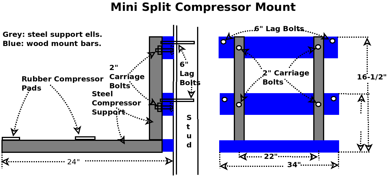
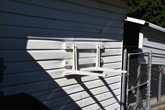
I will attach the horizontal support bars to the studs in the walls with 6" lag screws. The horizontal support bars will have 3/8" carriage bolts sticking out. Attach the steel support Ells to the 3/8" carriage bolts protruding from the horizontal support bars.
|
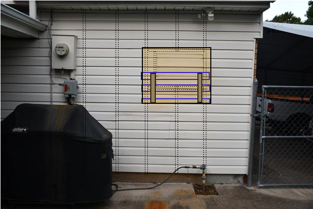
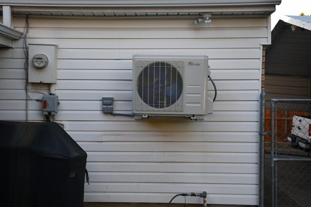
Outside of shop, I've superimposed the studs (dotted lines) and the outside unit (beige). Blue lines are the outside unit support frame (2x4s), darker tan lines are the outside unit support brackets (ells). Studs in the wall are on 16" centers. You can see the patch over the old AC hole and I added dotted lines to show the frame around it. Remember, the stud through the old AC hole middle was cut, horizontal 2x4s were added at the top and bottom of the window unit cutout, attached to the adjacent studs. The grill is moved to the left, normally it stays against the wall between the power inlet (left) and the gas riser (right). When I took the pic I didn't get it exactly square, the gas riser is on the right of the stud. |
|
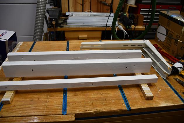
outside unit support bars, painted several coats since its going outside, you can see the 3/8" holes near each end. Note the 2 ell shaped steel outside unit supports, upper right. |
|
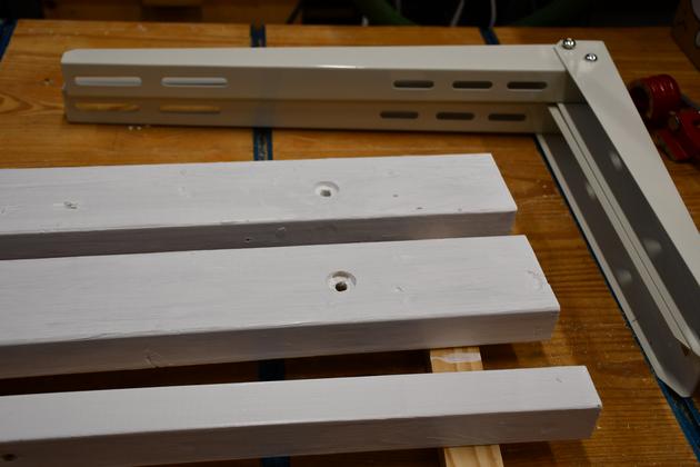
Back of outside unit support bars, note the counter sunk holes for 3/8" carriage bolt heads. Closer look at steel support ells. |
|
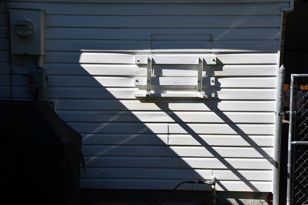
Outside unit mount, mounted to the outside of my shop. You can see the heads and washers on 5/16" lag screws on each end of mount bar. One good thing about having the outside unit up in the air like this is the unit will be able to draw air (on the building side) from all 4 sides (including underneath) which wll be exhausted out across the yard. |
|
The grill should fit under it and the outside unit should fit under the eave. Note the shadows, its about 10:00 AM in late October. The AC disconnect will be just to the left of the support bars with the whip swung under the outside unit to connect on the right side. I still have to figure how I get the outside unit up on the support. |
|
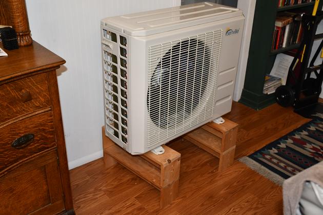
Outside unit up on support trestles. Raising it 12" makes it easire to lift, remember it needs to rise 50". Most of this thing's weight is concentrated on the right end (Where the outside unit is, I'm guessing). |
|
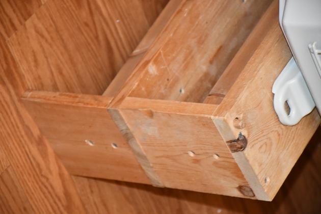
Close look at the outside unit's foot on top of two support trestles. |
|
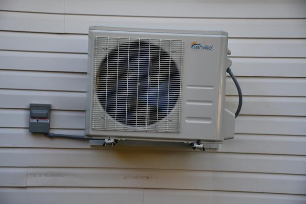
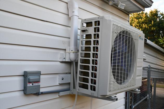
Outside unit in it's new home. Note the Disconnect to the left and it's whip circling around to the right side of the outside unit. I had to have help getting it up this high. |
|
A little closer look, note the disconnect on it's left. |
|
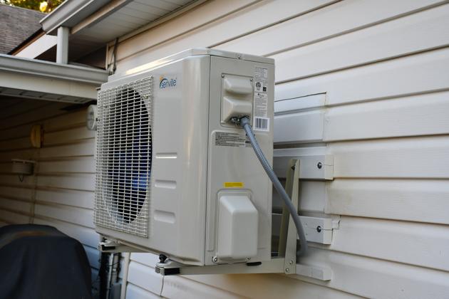
Right end of outside unit, refrigerant lines are next. |
|
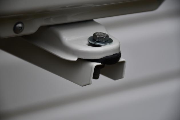
Note rubber mounting pads under outside unit mounting foot. The hex bolts are 5/16" with washers on both sides. The mount came with 8mm hex bolts and very thin (skimpy) flat washers. |
|
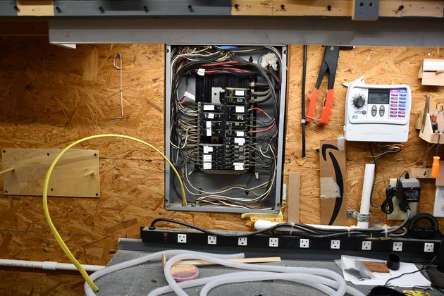
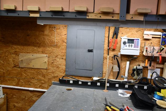
Breaker panel open with 12-3 w GND (yellow) sticking up from the bottom. |
|
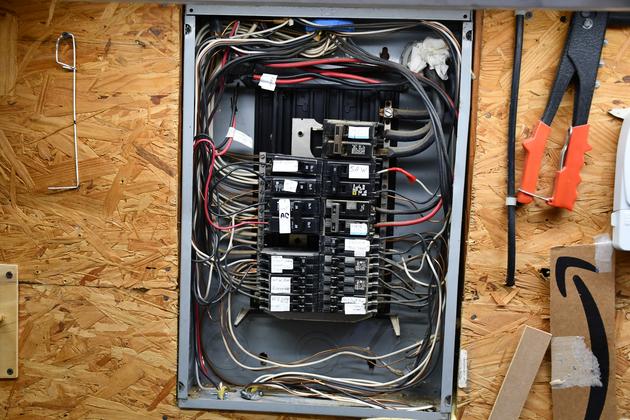
Panel with 12-3 w Gnd routed and attached. This is a Gould box, apparently the cheapest available when my house was built in 1982. It should really be replaced, I frequently check the temp of each breaker to be sure there isn't a high impedance or arcing going on. |
|
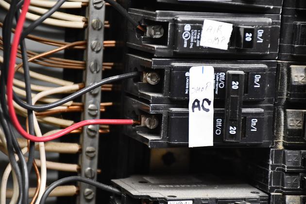
The shop AC breakers, note black and red wires attached (per the code), 20Amp breakers are open. I could have run this with 12-2 Wg, I would have had to use the white wire as hot, and put some red tape on it on both ends. |
|
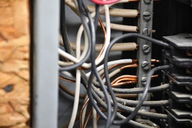
Both the return and ground attached to the goround buss bar. This is the only place (your main breaker box) you should ever tie these together. Also remember, I ran a neutral out to the disconnect even though it won't be used right now. |
|
Breaker panel cover replaced, breakers are open. |
|
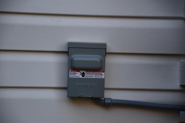
The disconnect. |
|
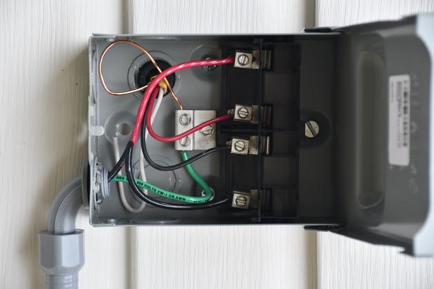
Inside the disonnect, the disconnect block is removed. Note the two 12ga 240 Volt (red & black), from the breakler panel, is attached to the two center terminals, the outgoing 10Awg (power whip) is atached to the two outside terminals. Also note the white return wire is not attached to the gound (metal chassis) only the bare ground wire. I brought the return to here in case I ever need a 120 Volt circuit out here. The return (white wire, is not needed in a single phase 240 volt connection) and is pushed back out of the way. There is only supposed to be one actual point, in the house wiring, where return is attached to ground and thats in the breaker panel. |
|
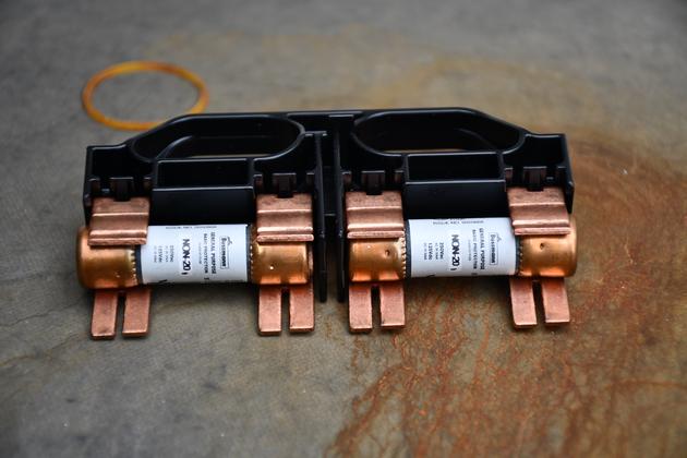
This is the disconnect block with two 20Amp fuses. |
|
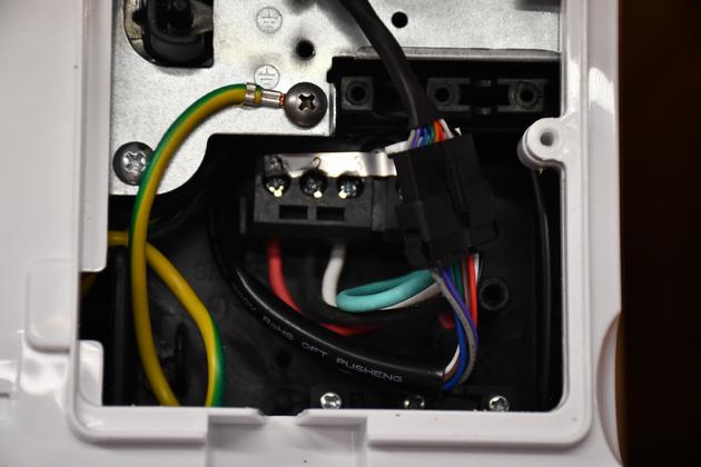
Inside unit cable connections. Note: Red is 1, Blk is 2, and Wt is 3. You can see the green wire (ground) but not where it is connected, green, by National Electrical Code is always ground. |
|
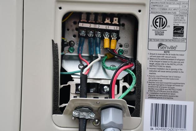
Wiring at outside unit. On the left, cable from inside unit: Red is 1, Blk is 2, Wht is 3, and Grn is ground. On the right, power whip, Blk is L1, Red is L2, Grn is ground, and is attached to the metal chassis plate. |
|
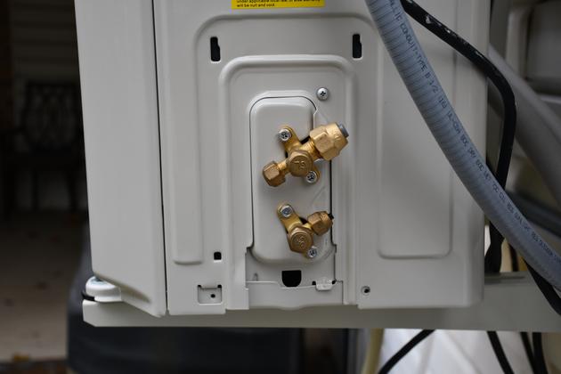
Outside unit with refrigerant connection cover removed. |
|
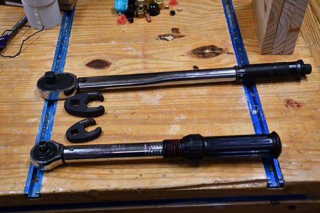
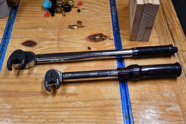
Both my torque wrenches, 1/2" drive upper, 3/8" drive lower, with the flare nut crowfoot wrenches. |
|
Torque wrenches with crow foots attached at correct angle. When you use a crowfoot on a torque wrench, you have to keep the crowfoot at a 90° angle to the rest of the wrench so you con't change the distance from center of drive to center of handle would change the torque setting. The 3/8" (for 14" flare nut) torque wrench calibrated in inLbs so I set it to 132 inLb. 1/2&qot; torque wrench (for 1/2" flare nut) set @ 26 ftLb |
|
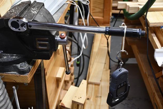
Checking calibration of my 1/2" torque wrench, using a digital scale.
The handle measures 14" from center of drive to middle of handle (show in pic), and 14" = 1.1666 ft, so to set it at 35.5 ftLb, 35.5 / 1.666 = 21.3 lbs.
I pull down, gradually, until the torque wrench clicks, the digital scale holds the peak reading.
I repeat this, changing the setting until the click comes at 21.3 Lb.
|
|
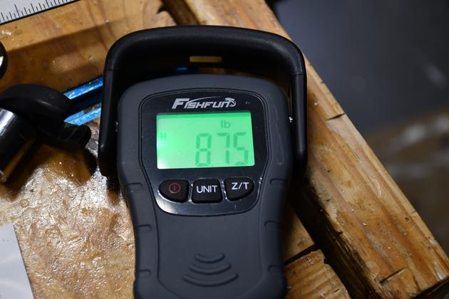
I set the torque wrench at 10 ftLb, pulled down on the scale's handle till it clicked. I pulled several times getting 8.5 - 8.75 Lbs averaged 8.6. 1.1666 X 8.6 = 10.03 ftLbs. |
|
All connections on the outside unit, refrigerant lines not wrapped, till after vacuum and leak test. Note: the extra refrigeration lines looped in a horizontal plane to prevent oil trap. I'll pull the loop down a little when I wrap it (after vacuuming the system down). |

|
Line set cover showing drain exiting at elbow. |
|
Line set cover is not against the wall since I had to clear the outside unit ell mounts. |

|
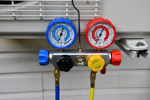
Vacuum setup, yellow line from vacuum pump to manifold, blue line from manifold to gas return connector on outside unit. |
|
A little closer look at the manifold, there are two ports on each end, all open into the manifold, The very end ports are controlled by the end valve knobs (blue and red). The blue and yellow knobs are open when pumping. |
|
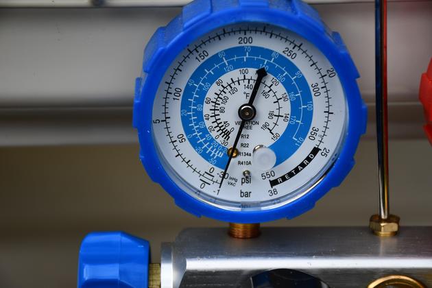
Vacuuming complete, yellow knob (to vac pump) closed, blue knob still open (I'm seeing the system's pressure), low pressure valve showing -30psi vacuum. Now I'll wait awhile to see if it holds. |
This thing works great!!! Its a little strange to watch it work, it ocassionally moves the outlet door (at bottom of unit) up and down to distribute the air better. When it cools, it cools the room a little lower than the setting, then allows the room to come to the set temp and keeps it there.
|
|
Inside unit, running, you can just barely see in the pic the temperature is displayed (70) in fairly large numbers, in the center of the unit.
Apparently, like most LED displays, the temp digits are being scanned, note how bright the '7' is and how dim the '0' is.
|
|
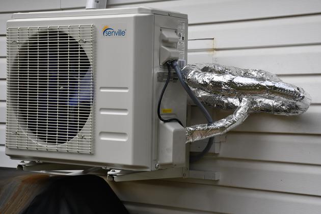
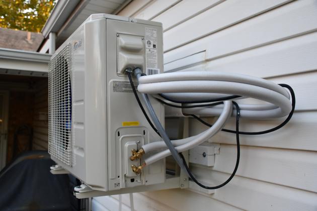
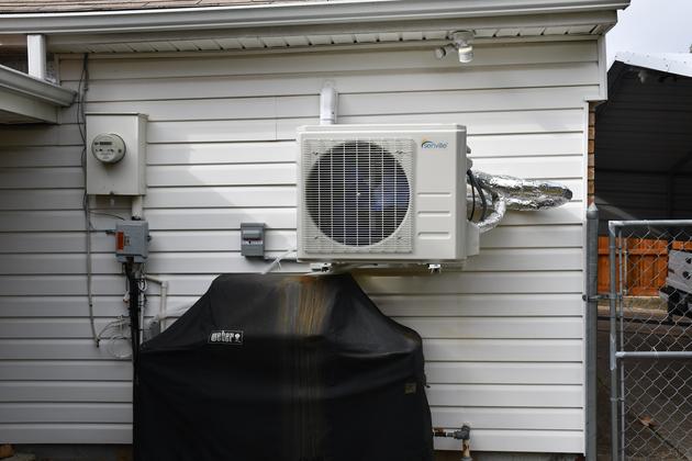
Outside unit finished, the lineset is partially covered by note I wrapped the exposed lineset so it was a little bettre protected from the elements. The grill is back against the wall, just under the outside unit. |
|
|
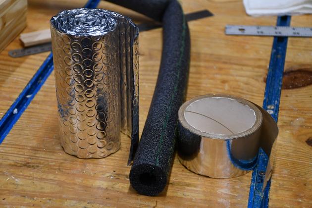
I tripple wrapped the lineset which is already insulatd, first in aluminum backed bubble wrap, then covered all the joints with HVAC foil tape. My only surprise was the outside unit drips water from the multiple slots in the bottom, not just the drain hose, but it isn't a problem. |
|
The aluminum backed bubble wrap (left), Aluminum AC tape (right), and foam tube (center). The foam tube is split down the side and has peel off strips inside the split. I use this every where the line set insulation wasn't long enough. |
|
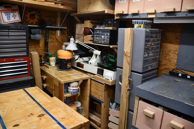
Shop small East corner. |
|
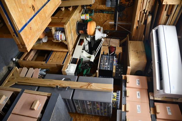
Taller look at NE nook, with new mini split near the ceiling, and new storage shelves below it. Betty said this looked extremely compact (crowded), but I can access everything fairly easily.. |
|
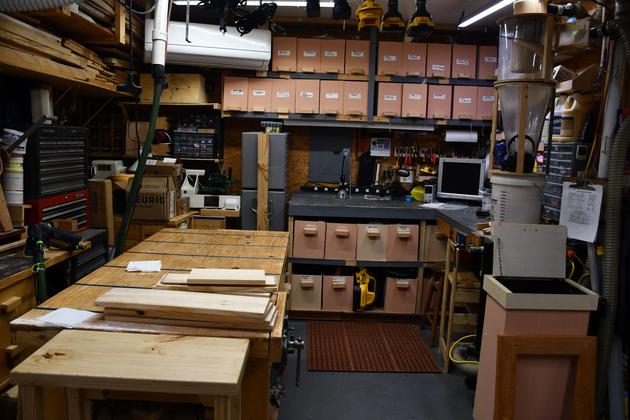
Looking straight East, into the nook. |

|
|