| 
|
|
Arduino controlled 240V Blower Switch
| |
|
|
|
|
Arduino controlled 240V Blower Switch
| |
| Back So Automation | Back EMF | Input Current Test | Diagram |
| Switch | Home 240 Volt AC |
In order for an Arduino to control a 1-1/5 - 2 horsepower Dust Collector Motor I have to use some kind of hefty switch.
The highest powered Arduino relay module I could find was 30Amp and only rated at 1/2HP.
I need a relay that can withstand the back EMF generated by switching large motors off.
Years ago my friend Herb Hanson found the Crydom SSR (solid state relays) for a project we were working on at the time where we needed to control Bodine geared motors.
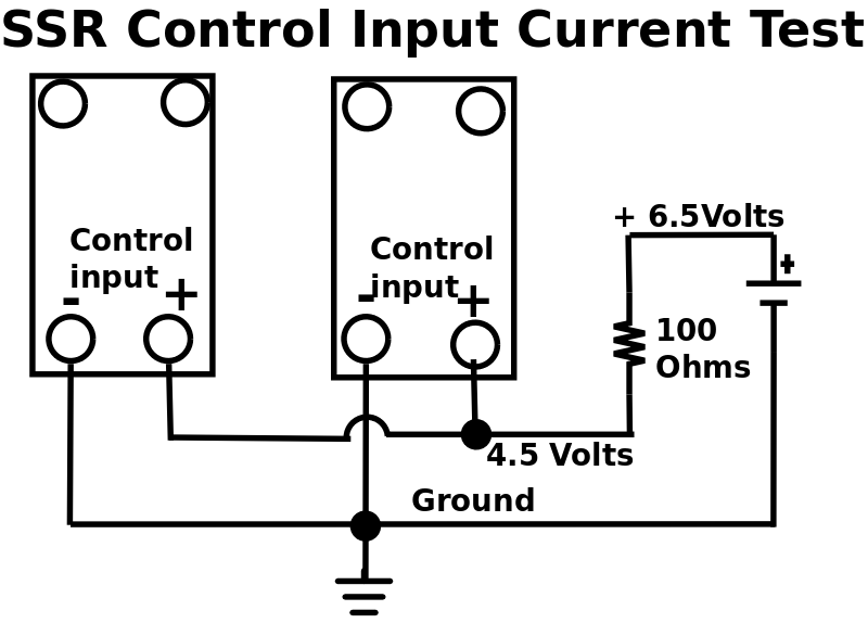
The control input is 3-32 volts at low current ( ≅10 MA) and is optically isolated so you don't have to worry about getting your Arduino's grounds connected to the 120/240 volt grounds.
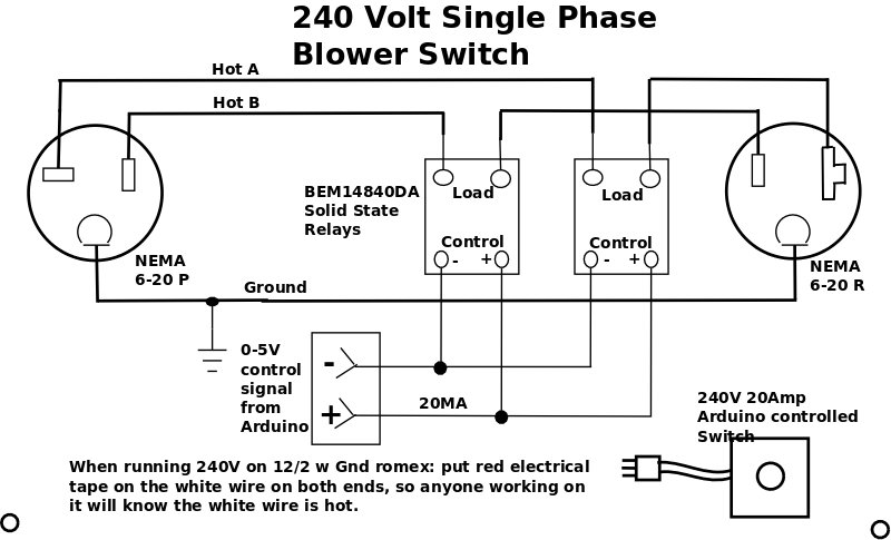
To switch 240Volt single phase (since it has two hot wires) I need a DPST (Double Pole Single Throw) switch, SSRs are SPST (Single Pole Single Throw), so I'll need two of them.
Over the years I have applied several SSRs and am a real fan.
Sure enough Amazon listed several and I chose the BEM-14840DA 3-32V DC to 24-280V AC 40a SSR cost $10.79 (at purchase time) 40Amp, 280 Volt, which isn't bad considering you won't have to worry about it dying any time soon.
SSRs are a little pricyer than the Arduino relay modules but I've never had one crap out switching a motor, and they make some honkers that'll switch almost anything.
Amazon has some other SSRs lower price and current: the SSR-250DA from CG is nice, the HiLetgo SSR-25DA gives you two for the price of one, but note these are 25 Amp switches which should be OK for 2HP or less.
Remember, the input surge when the SSR first turns on.
These solid state relays can easliy be switched by an Arduino digital output and can handle large motors.
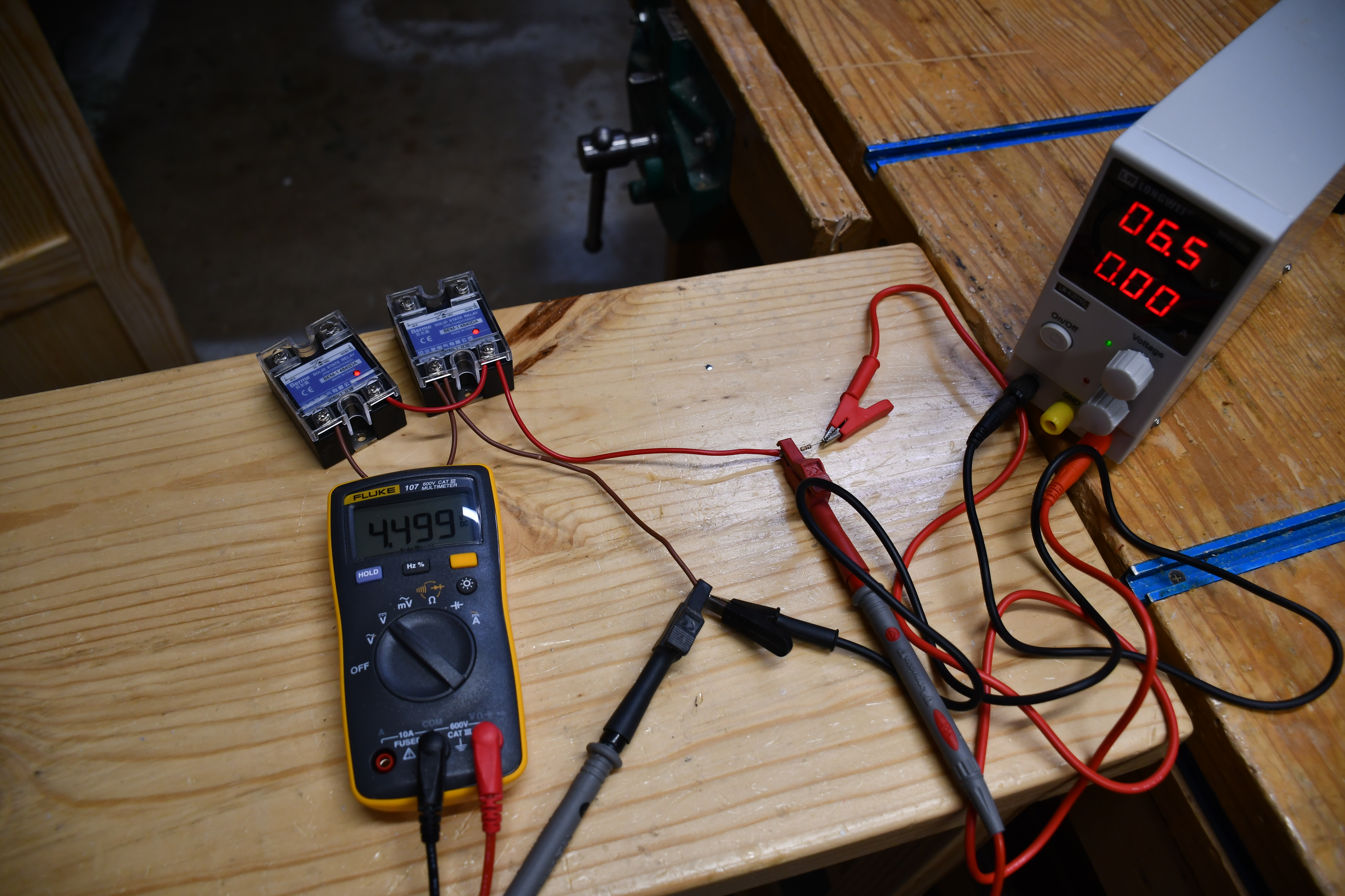
I will soon run a test to see how much input control current 2 SSRs pull.
If the current is > 40 MA (one Nano output pin), I'll add an emitter folower to boost it's current capacity.
I mounted the SSRs in a double gang steel box with a 1' 3 prong, 14ga pigtail (15A circuit) and a dual receptacle.
I bolted the SSR to the metal box to add as a little heat sink.
My Dust Collector blower runs on single phase 120 Volts, so I only need one SSR, but if your DC runs on 240 Volts, you'll need two to switch both hot wires, to be safe.
In essence, a DPST NO (Double Pole Single Throw Normaly Open) switch.
Back EMF is the voltage generated by a motor that keeps the motor from appearing as a short across the input voltage.
Please see my BackEMF page.
|
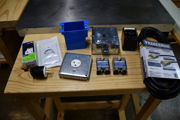
All parts except hook-up wire to assemble. Note I have drilled the hole and installed the input power cable clamp. Still waiting on the 12 AWG hook-up wire. The blue cut-in box, single white faced plate, 240 V receptacle, are for the new 240V 20A circuit for the new blower. I have found its cheaper to buy a 25' 12/3 extension than SO cord (SO cord means it is for hard service, < 600V, and oil resistant). I also note, on the Jet DC-1200 manual, the power cord is 14/3 for the 2HP single phase motor. |
|
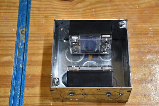
Two SSRs bolted to sides of 4" square box. I still have to drill the hole for the control signal, and the input 240V. |
|
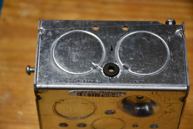
Hole drilled and gromet installed for control line. |
|
|
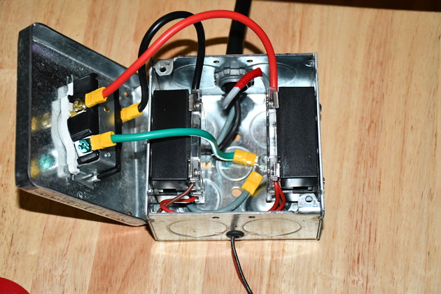
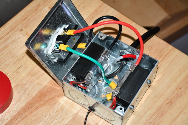
Hi Power switch being assembled. Note the green wire from the receptacle, along with the greyer wire from the SO cord (looped around), is tied the box I tried to keep the control voltage in the near end of the box, and the high voltage to the far side and ground in the middle. |
|
View from a little different angle. Note the white wire at the top of the box with red tape, white wire in a house is return, unless you mark it with red tape then its a hot wire. |
|
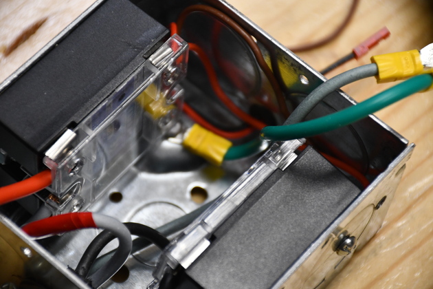
You can see the two SSRs bolted to each side, and if you look carefully, you can see the small red and brown control wires from the DA system. Again the white wire with red tape, this time on the left. Actually, the SO cord was a 12-3 extension and had black, grey and greyer, so I chose the grayer for ground, and marked the gray with red tape. |
|
|
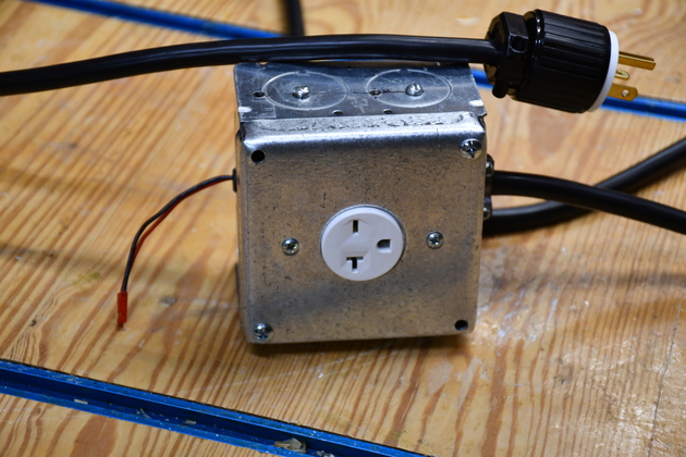
All finished, control connector on the left 240AC input on the right and output plug on top. |
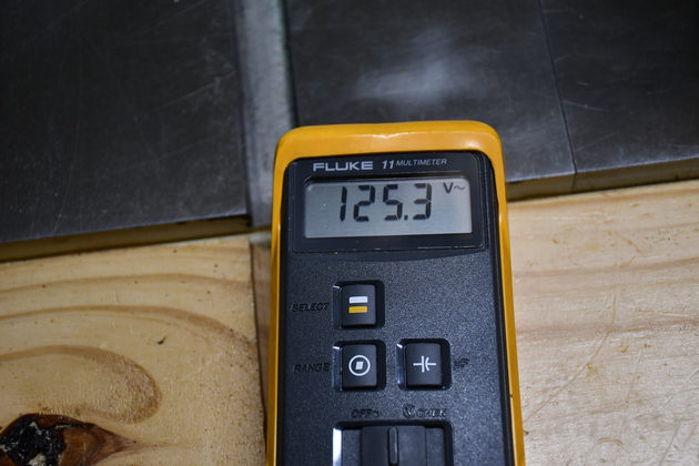
In case your wondering why I always talk about 240 Volt and 120 Volts at home instead of 220 and 110, here are the voltages measured on both my Fluke VOMs. The local power company (North Texas, Oncor) keeps our lines at 125 Volts and 250 Volts, not 115 Volts and 220 Volts.
|
One phase of my home power, 125.3 Volts. |
|
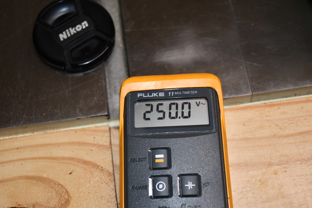
Across both phases 250Volts. |

|
|