| |
|
| 
|
|
John's Mobile Loading Bench
|
05/22/13: Frame complete.
04/29/13: Work begins.
02/27/13: Add description and links.
12/28/12: Origin.
My son John who loads .45 ACP, exclusively, asked me to build him one of my mobile loading benches.
He has been using an RCBS Rockchucker on a small desk in their living room as his loading bench.
I decided to combine what I did on Bill's printer storage project with the changes on Kyle's bench on this project.
I am going to build this bench with squared off edges on all the frame pieces, so it'll be a little different.
The outside dimensions will be the same.
The drawers will be about 1/4" wider.
I may also use birch plywood instead of fir.
The top and plywood panels are an integral part of the frame of a loading bench.
Normally, I assemble a bench frame from the top down (upside down), however, in some of the pics below I show the frame from the bottom up just to illustrate how it looks as most folks normally think of it.
There are three different construction pages here, each has pics showing different aspects of loading bench construction, between them you should be able to see about anything you need (or want to see).

|
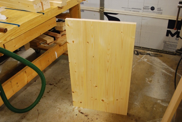
The lumber (2x and 1x) arrives home for John's Loading Bench.
I already had a full sheet of 1/2" birch plywood so I didn't need any more this time,
The 1/4" plywood for the drawer bottoms and bay floors is in the bed.
The hardware (slides, casters, locks, etc.) is in a sack in the cab.
|
|
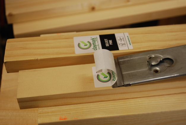
First, remove the Home Depot labels.
|
|
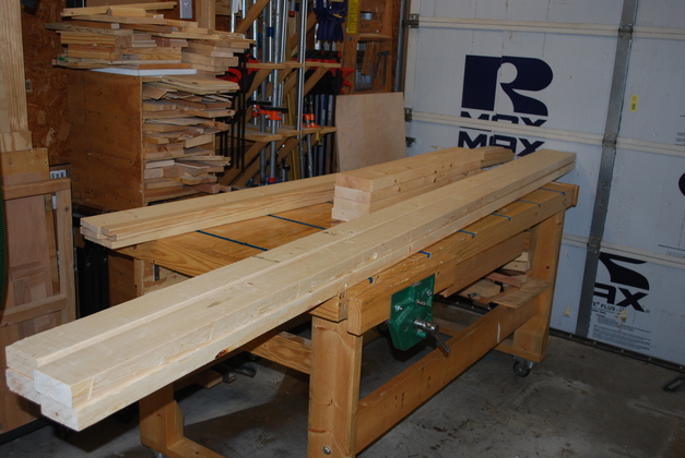
Here is all the lumber for John's loading bench layed out on and behind the workbench.
You can just barely see the 1/4" plywood standing up at the rear.
The 2x6s are already cut into 36" lengths, ready to run across the jointer.
|
|
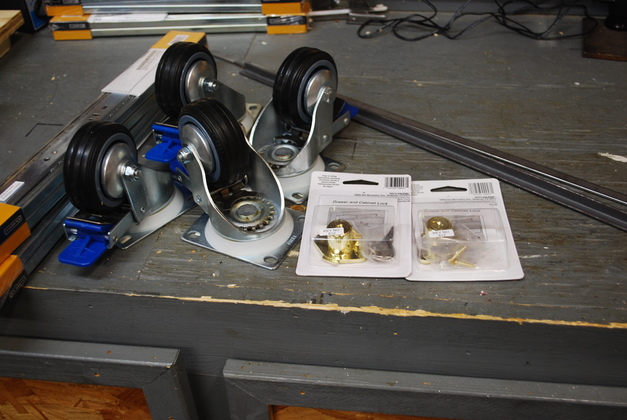
The hardware, slides, double locking casters, drawer locks, 1/2" angle for lock strikers, and 1/2" strap for press base catches.
|
Go here to see the frame member's machining into square flat boards.
Frame
|
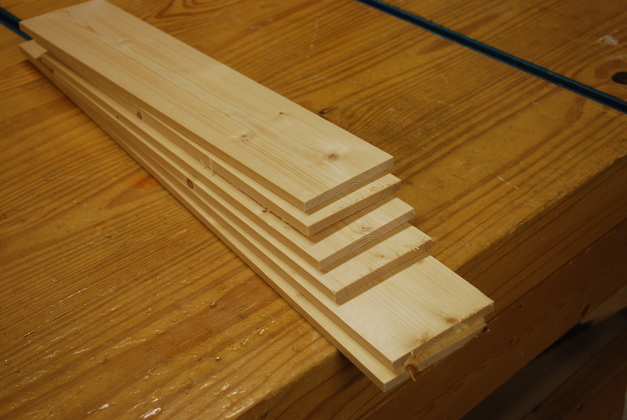
The top pieces cut to length.
|
|
Now they've been machined square and the front pair and back pair are being joined.
|
|
Here the front and back sections are being joined.
|
|
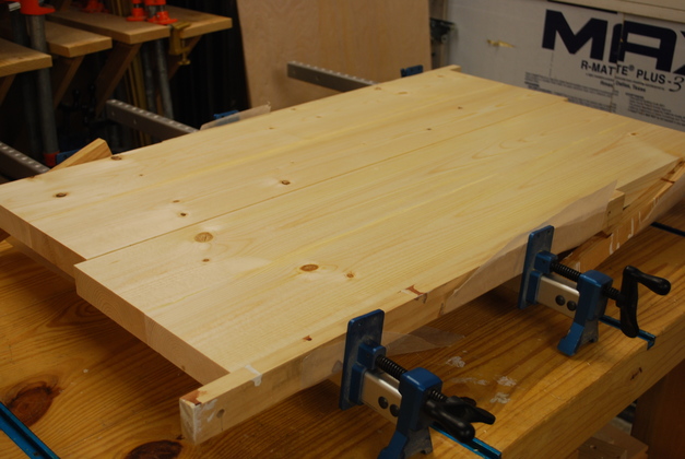
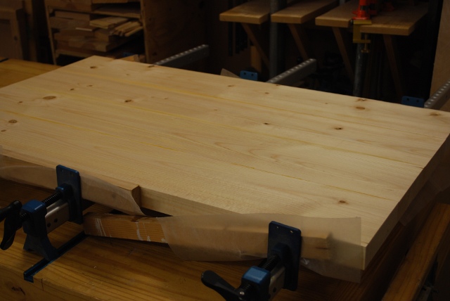
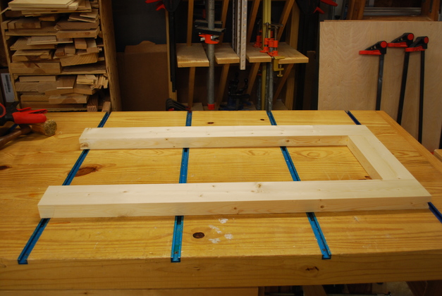
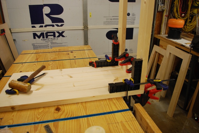
Four sections of the top are joined (glued) and ready to trim and sand.
Remember, the four 2x6s are a little over 20" wide and the table should only be 18".
Next I start working on the other 5 frame members, left, center, right front, right back, and bottom stringers.
|
|
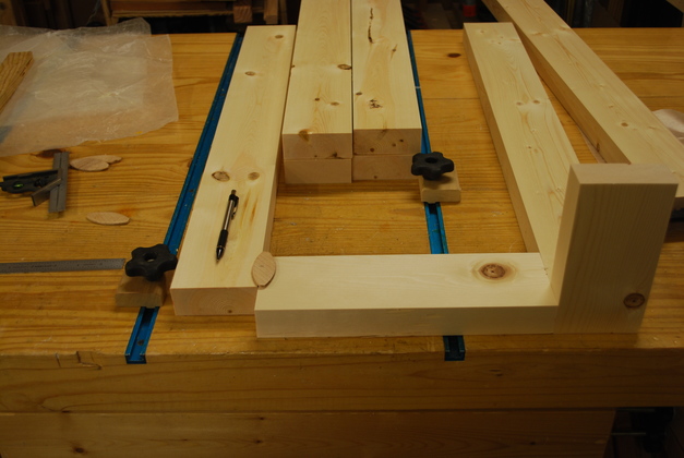
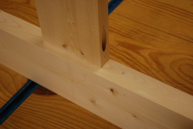
Here I'm marking the verticals for slotting.
The short machined 2x4 standing on end on the right side is to make sure the notch is the right size for the stringer.
|
|
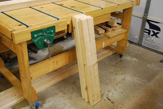
Vertical in the glue clamps.
|
|
One of the verticals glued and ready to sand.
|
|
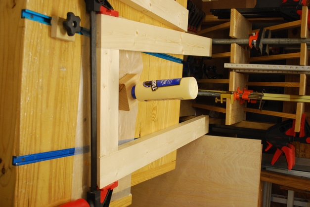
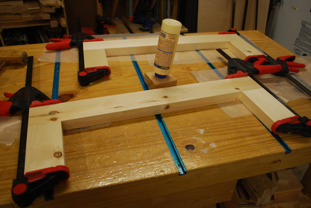
Bottom stringers being glued.
Do you like my expensive glue bottle holder, it keeps the glue at the nozzle end so I don't have to wait when the bottle isn't full.
Should I make a diagram of this????
The block is a 2x4 3-1/2" long with a 3/4" hole in the center, 1-1/4" deep.
|
|
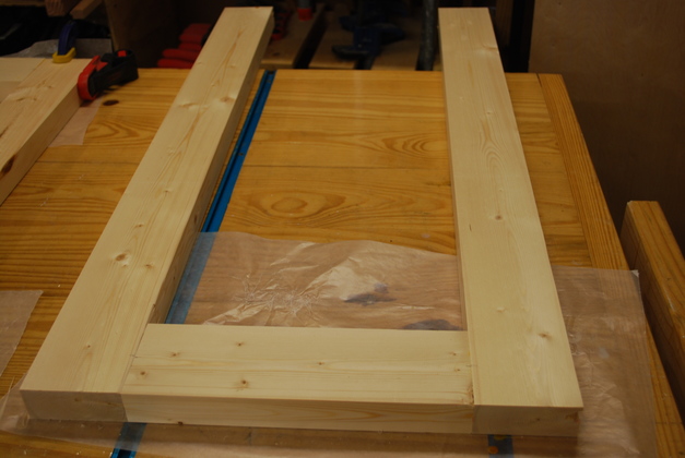
Bottom / stringers glued.
This end goes under the loading bay.
I've' still got to glue up the front/back verticals that go on each side of the loading bay.
Then lots of machining to be done: cut rabbets for 1/2" frame panels, then rabbets for bay floors.
|
|
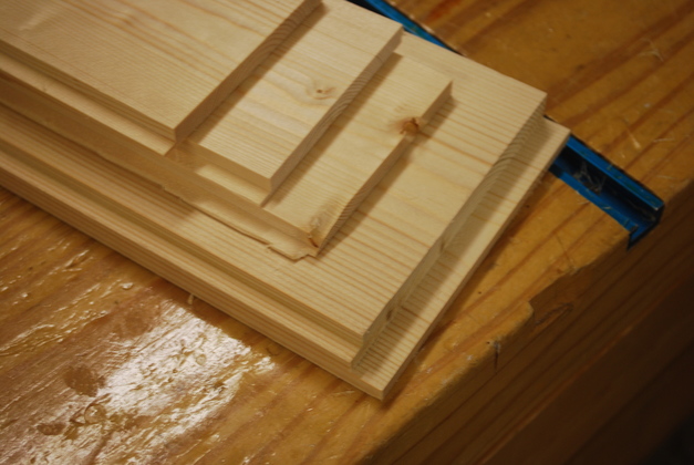
The front and back frame pieces (loading bay or right end).
|
|
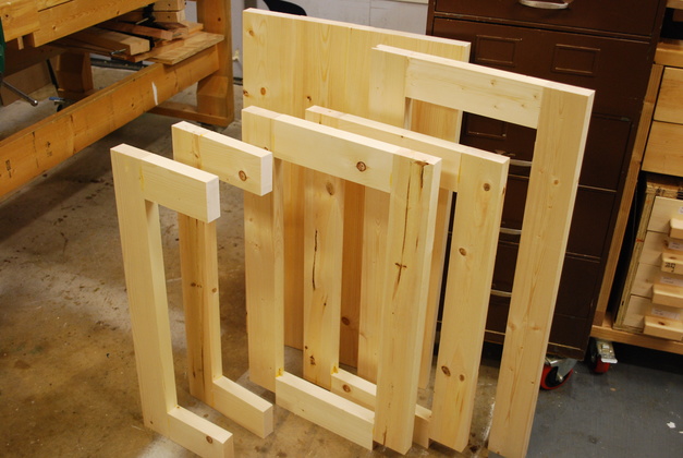
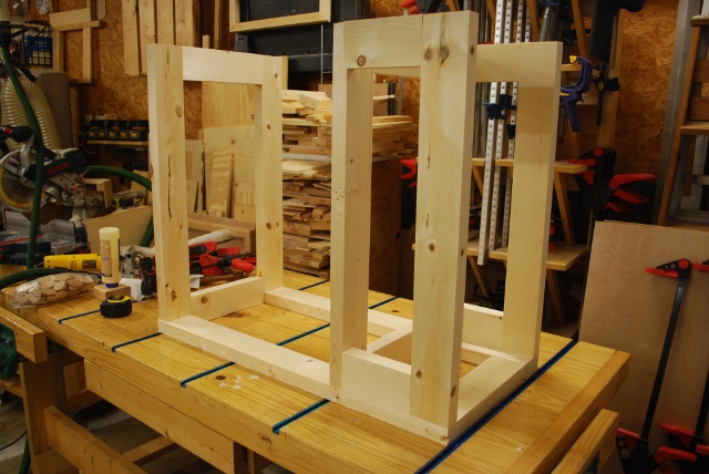
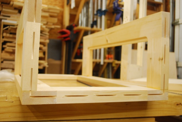
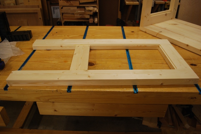
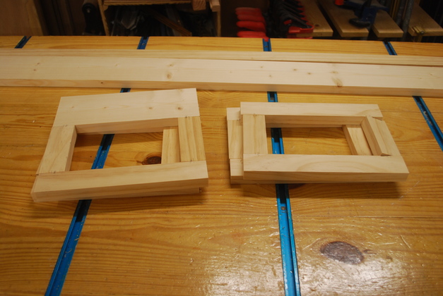
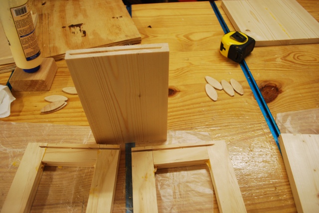
All the frame pieces glued, ready for panels and assembly.
|
|
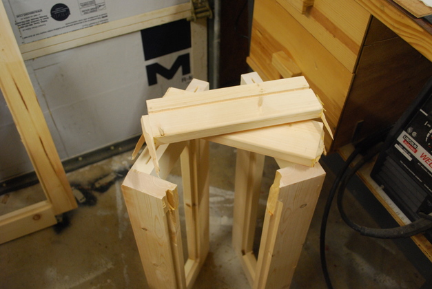
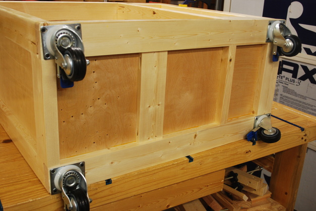
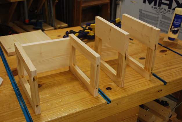
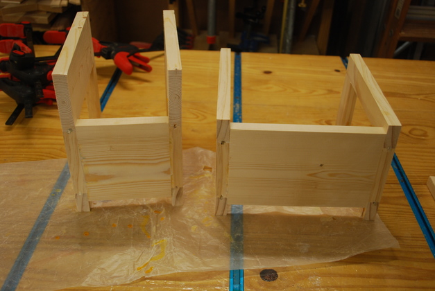
How the frame goes together - the Bottom Stringers.
|
|
How the frame goes together - the front and back (loading bay end) in position on top of the bottom stringers.
No glue, pieces are just sitting there.
|
|
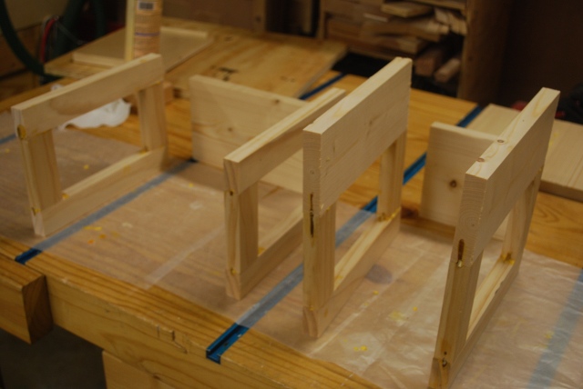
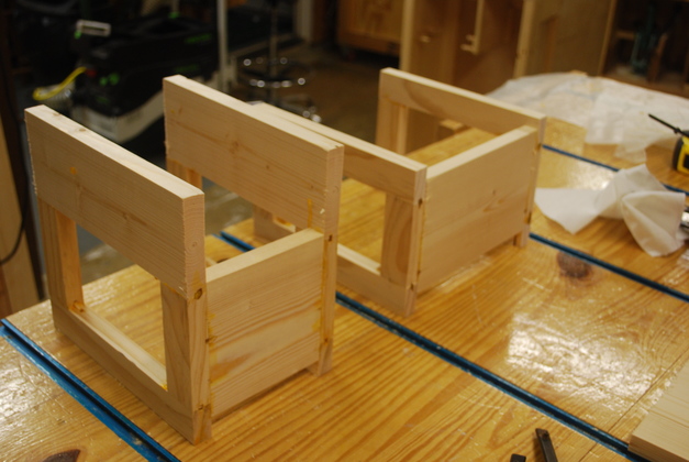
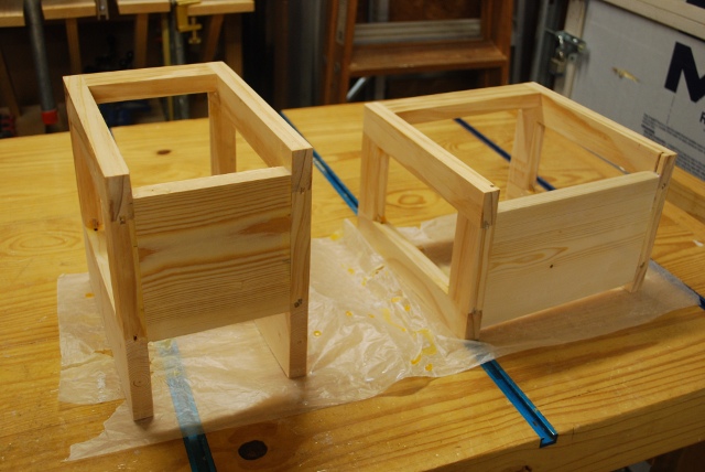
How the frame goes together - the right end (or center) frame piece.
No glue, pieces are just sitting there.
|
|
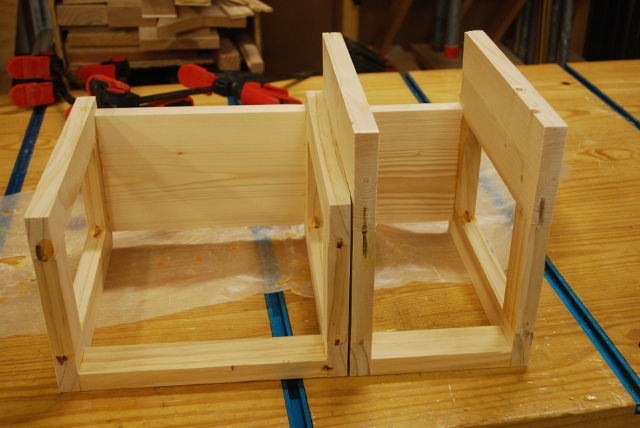
How the frame goes together - the left end frame piece in position on top of the bottom stringers.
No glue, pieces are just sitting there.
The top sits on top of these frame pieces.
|
|
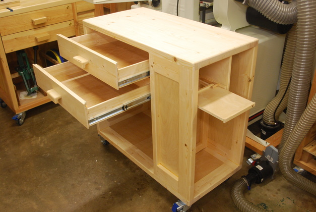
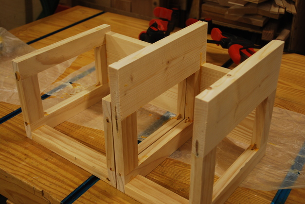
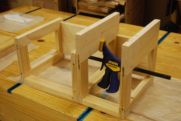
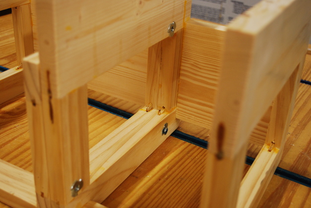
Front right quarter of the frame, without top.
No glue, pieces are just sitting there.
I assemble the frame in the reverse order, starting by gluing the left frame piece onto the top.
|
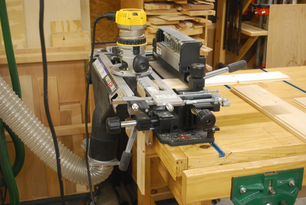
The frame pieces are rabbeted for plywood panels and floor panels then slotted for biskits.
Please look here for pics and details.
|
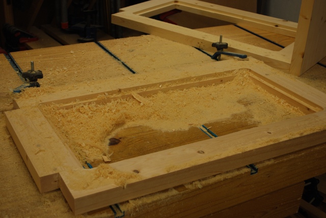
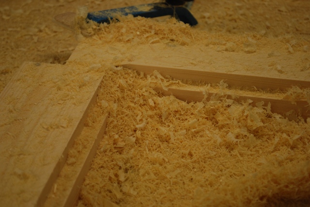
Wood chips from cutting one panel rabbet.
|
|
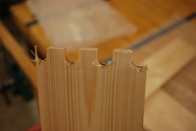
Close up After cutting one panel rabbet.
|
|
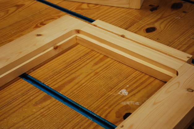
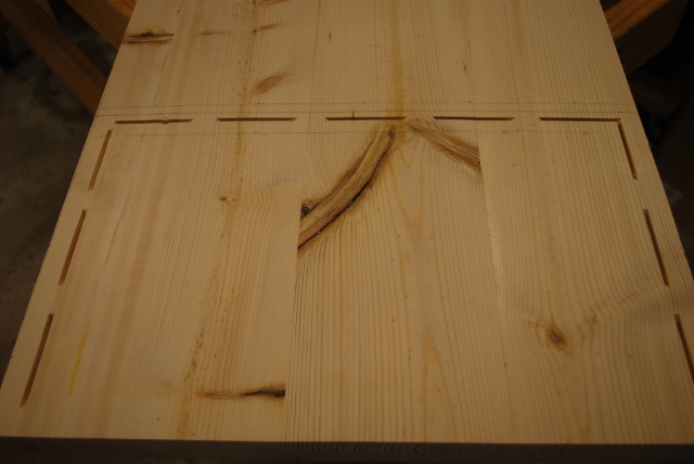
Panel rabbet and floor slot in main bay side of center vertical.
|

|
Panel slots and floor slot in loading bay side of center vertical
|
|
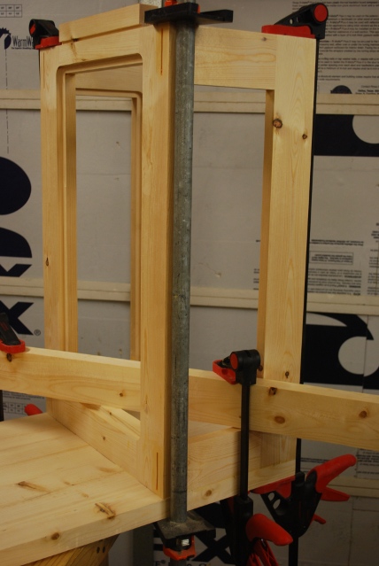
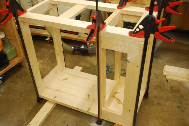
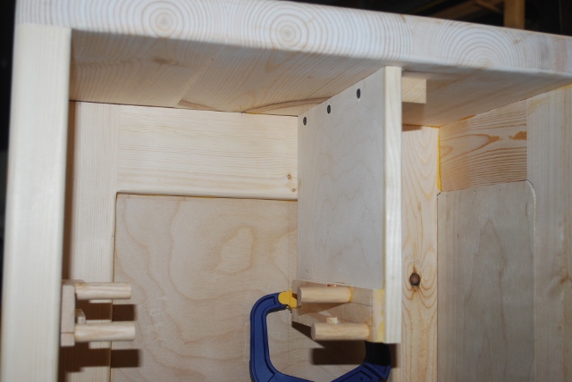
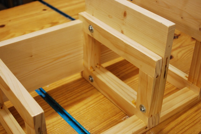
Now frame assembly begins, by gluing the left vertical frame piece to the top.
Since the top is an integral part of the frame and the largest piece, I glue all the other pieces to it and to each other.
You can see the Rockler "ClampIt"s in the corner, they force the top and end piece joint to be square.
|
|
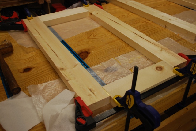
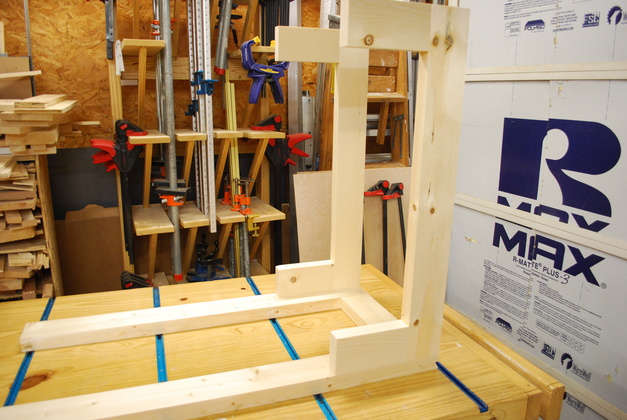
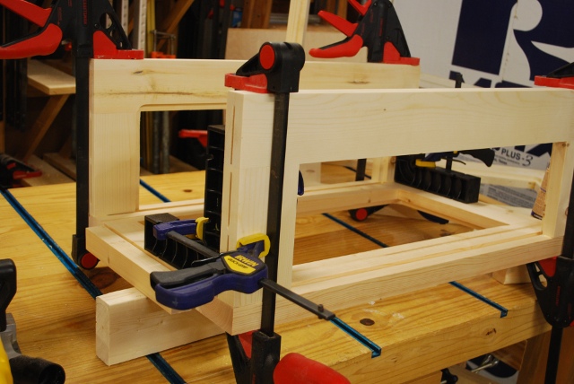
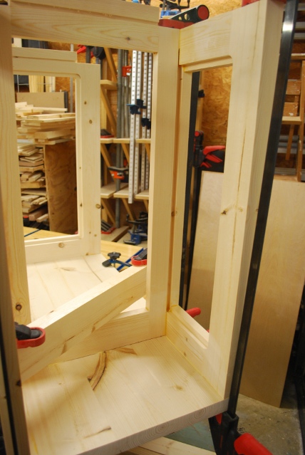
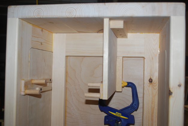
Loading bay frame being glued: center, front, and back verticals.
|
|
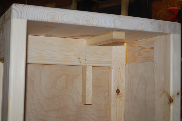
Top of loading bay frame.
You can also see some of the biskit slots for attaching the bay frame to the top.
|
|
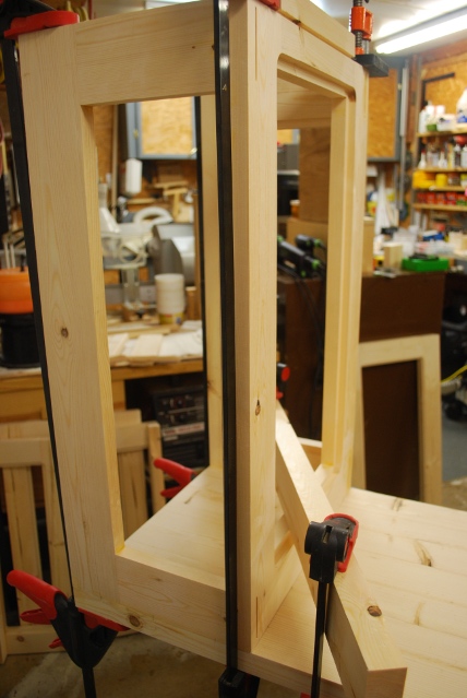
Looking down from loading bay top, you can see the two ClampIts making sure everything is square.
|
Here I had a small catastrophe.
After the glue set on the loading bay frame (pic above) and as I was positioning it to mark for slotting to the bench top, it fell off the workbench and broke.
The break happened as it normally does with glued joints, the glue doesn't break only the board.
Hence, I am rebuilding it from scratch.
I went to Home Depot and got two more 10' 2x4s which I cut into the 10 correct lengths, then ran each face across the jointer twice (thats 40 passes).
Tonight, the 4 verticals and 6 horizontals are all in the glue clamps.
Tomorrow, I'll cut rabbets, round off corners, and cut slots preprartory to regluing another loading bay frame.
|
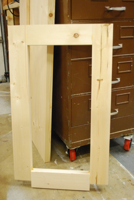
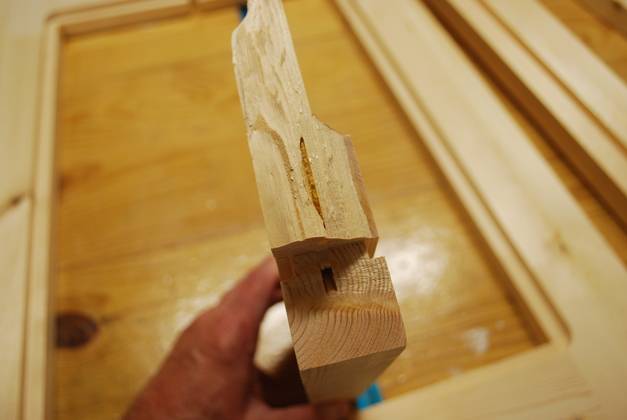
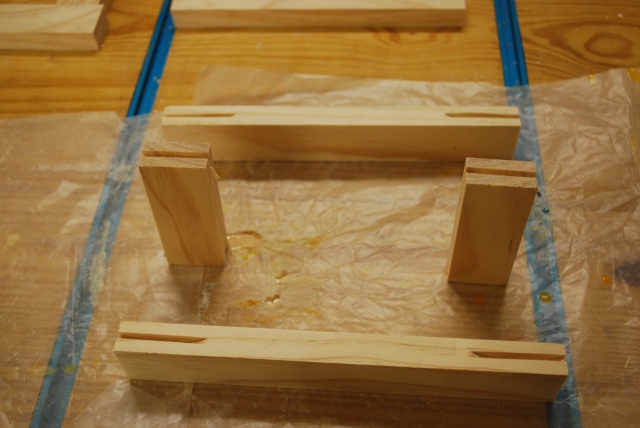
Here are the pieces.
You're looking at the top of the loading bay frame with the two horizontals laying on top, the front vertical is on the right, the back vertical is on the left.
The center vertical broke near where the horizontals glued to the verticals, you can see parts of the verticals still glued to the ends of the horizontals.
|
|
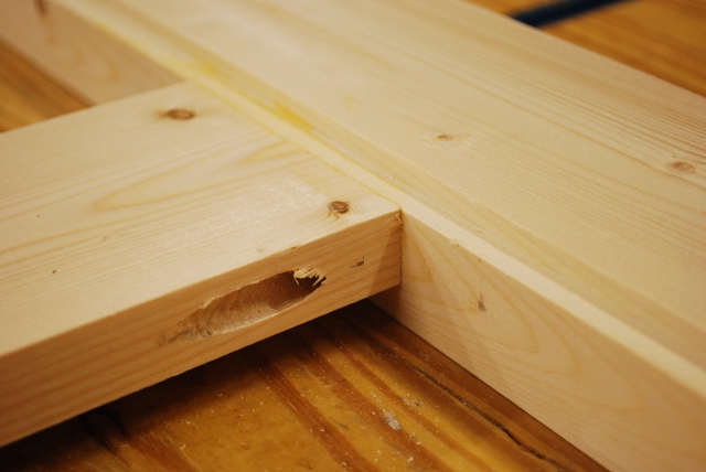
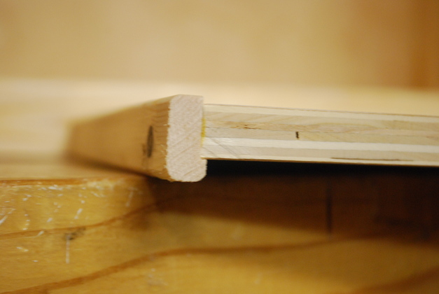
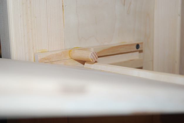
The wood itself (white wood not yellow pine) broke, not in a knot and the glue joint didn't break.
This is one end of a bottom horizontal with wood from the center vertical, you can just see the end of a biskit and floor grooves.
This is where one of the bottom stringers would go.
The break speaks well for Titebond and biscuits.
|
|
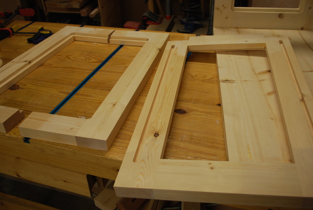
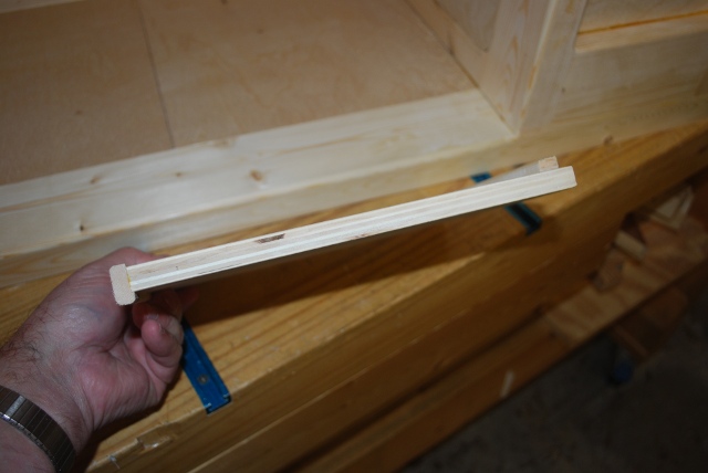
New center vertical with front and back verticals (on left), sanded, rabbeted, and slotted.
Next the floor groove in the center vertical then biskit slots for gluing the loading bay frame, and I'm almost back where the catastrophe happened.
|
|
Underside of bench top, loading bay end, showing biscuit slots for loading bay frame.
|
|
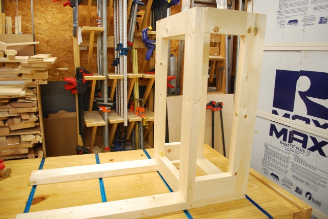
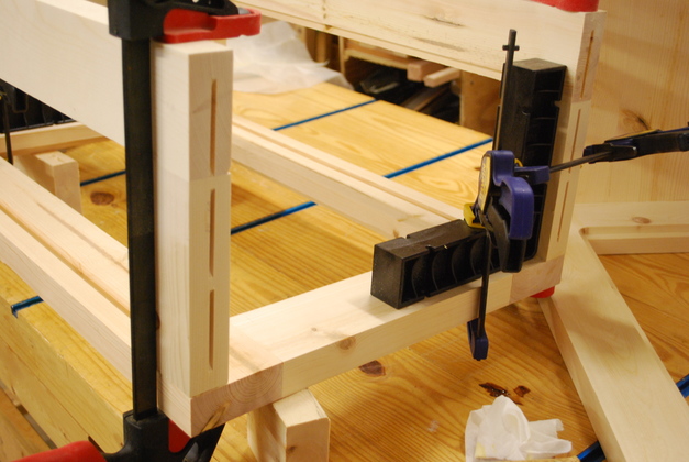
Top of new loading bay frame glued and ready to glue to table top.
You can see the biscuit slots in frame that match table top slots in above pic.
|
|
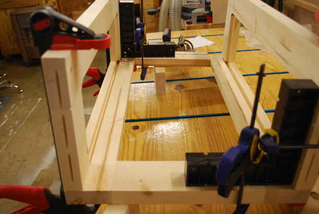
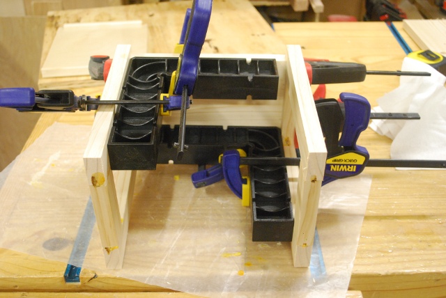
Loading bay frame being glued to the underside of the table top.
Lots of clamps.
Getting all 11 slots to line up perfectly is a little ticklish.
|
|
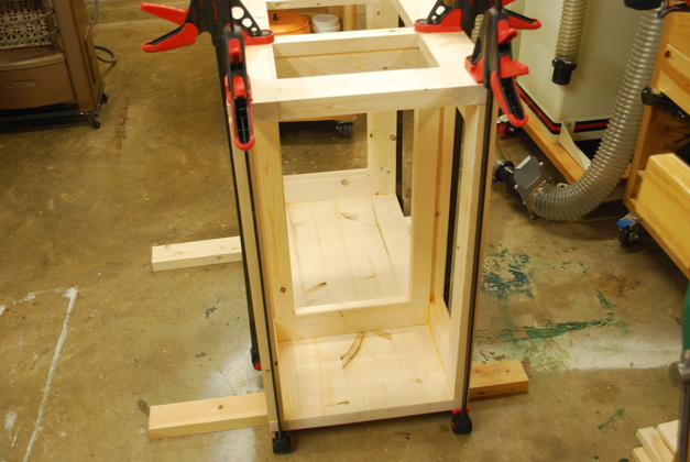
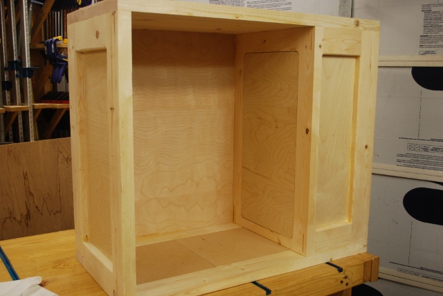
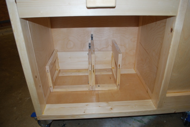
Looking inside the loading bay (upside down).
|
|
From the front side (still upside down).
In the background, on the left, you can see parts from the catastrophe.
|
|
Bottom frame piece (stringers), cross brace and main bay floor brace assembled, ready to glue to the rest of the frame.
|
|
Main bay floor brace seen from the bottom.
I should have put this in when I glued the stringers to the cross brace, but this is a relatively new feature so I forgot and had to use pocket hole screws and glue.
The main bay floor brace has now been added to the cut list and diagrams.
|
|
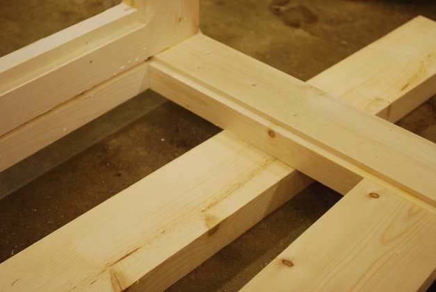
Main bay floor brace from the top, note the top of the floor brace is flush with the bottom of the floor rabbet in the stringer.
|
|
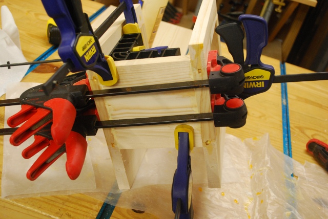
Bottom stringers/frame being glued to verticals.
|
|
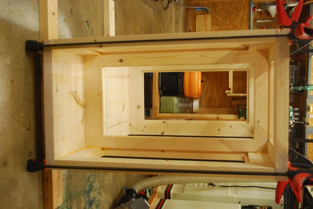
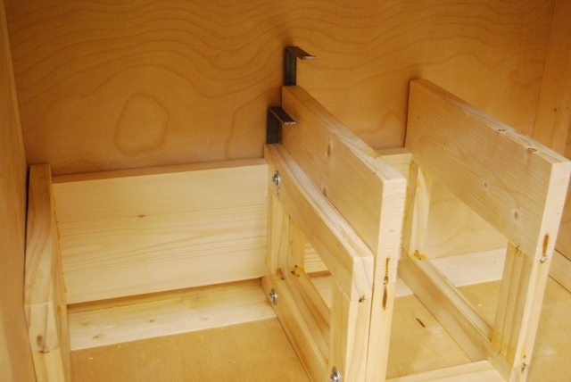
Look at the loading bay end.
|
|
I didn't intend to line this up but, looking through the loading bay end of the new frame you can see into the loading bay of my original loading bench.
|
|
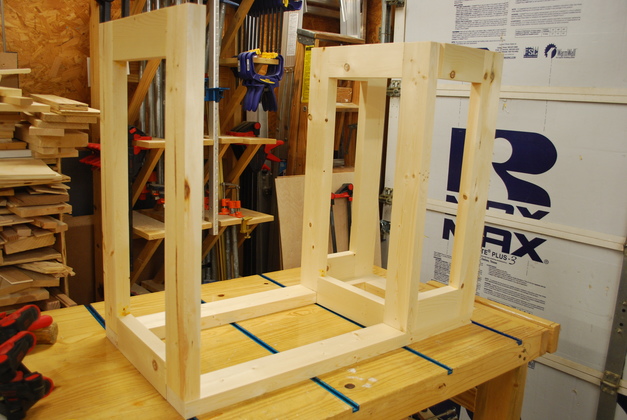
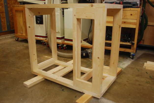
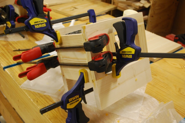
Frame glued, ready for panels.
|
|
You can see the floor rabbet in the far stringer and the groove in the left end frame piece, also the main fay floor brace flush with the bottom of the rabbet.
|
|
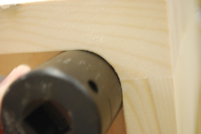
Here I'm finding which socket to use as a rounding pattern.
|
|
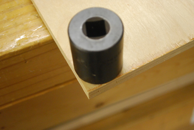
After I decide which socket to use, I use it as a pattern to mark the panel's corner rounding.
|
|
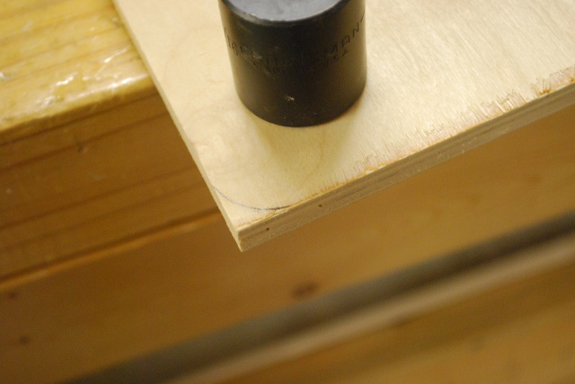
You can see the mark.
I'll jig saw off the corner then sand them on a disk sander before installing.
|
|
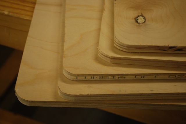
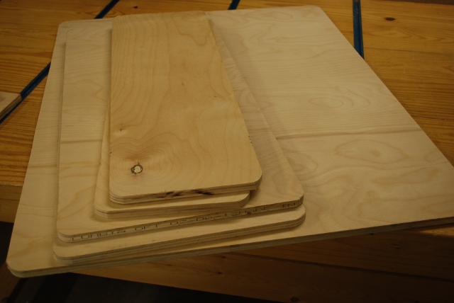
All panels rounded, now sand and install.
|
|
The whole stack of panels.
|
|
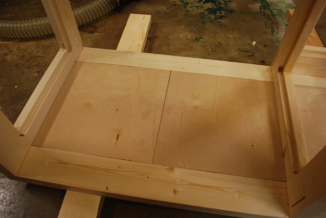
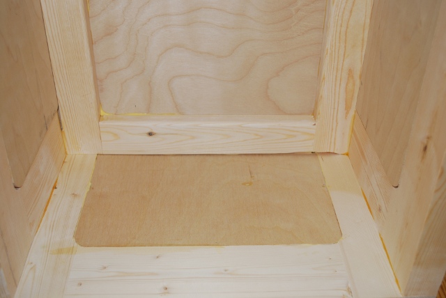
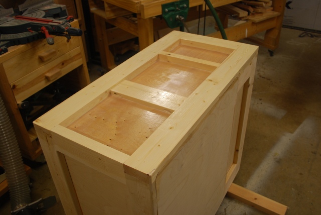
Test fit of main bay floor panels.
|
|
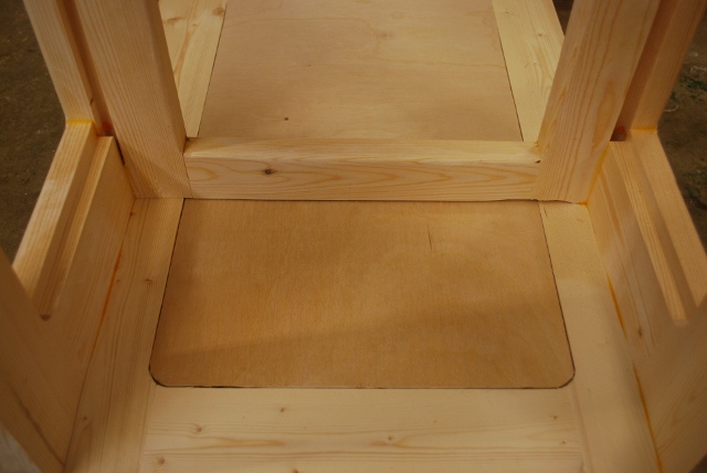
Test fit of loading bay floor.
|
|
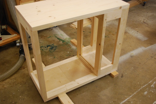
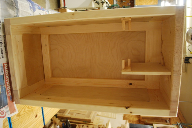
Open frame with floors.
|
|
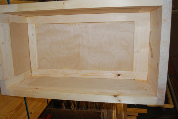
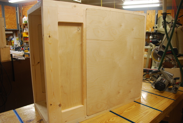
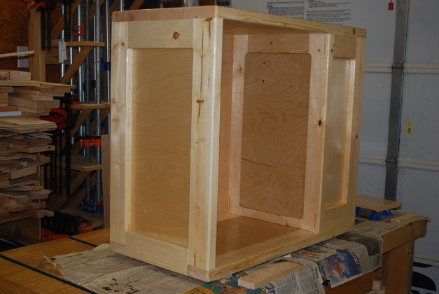
Front view with all panels and floors glued in.
|
|
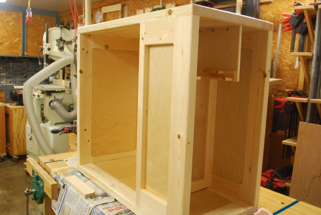
Loading bay with all panels and floors glued in.
The flash makes the birch look very light but when painted with poly, it'll be darker than the pine.
|
|
A little closer shot of loading bay floor and panels.
|
|
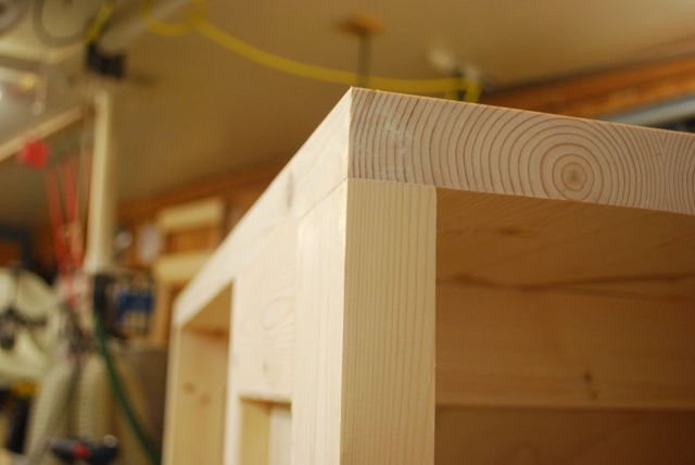
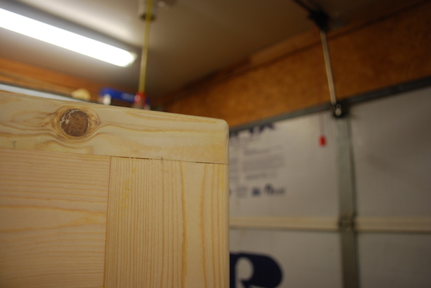
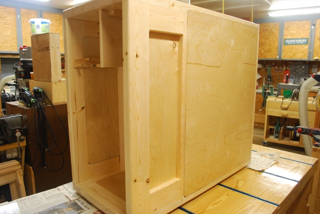
Frame sanded, notice how nice and square the corners are.
|
|
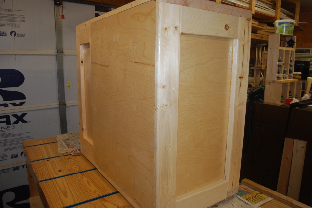
The back sanded.
|
|
Now look at the corners after they are rounded off.
|
|
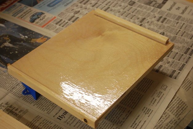
Sealer coats of poly on the bottom.
|
Loading Shelf
|
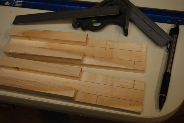
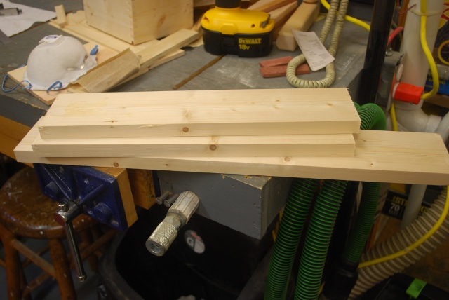
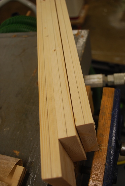
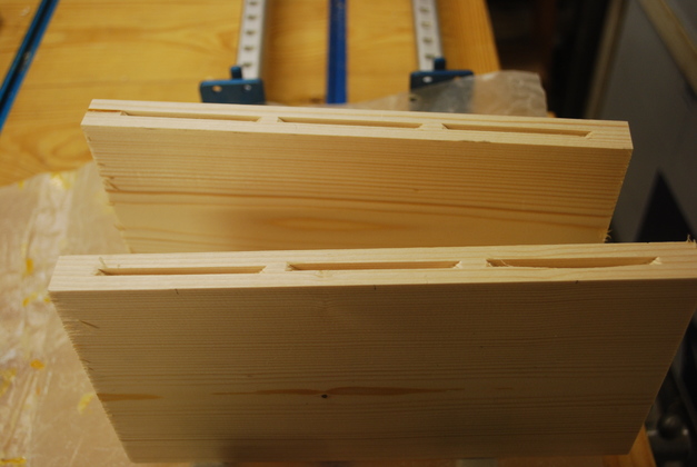
Slides for loading shelf cut out and machined.
I cut out two 6-1/2" long 1x2s then cut the slot down the center of one side then machined off the 3" on one end the same depth as the slot.
Since the piece of birch plywood is exactly 1/2" thick, I had to use a 9/16" rabbet bit to cut the slot.
I could have used a smaller bit and offset it slightly then made two passes on the router table, rotating the piece so it cut a wider slot.
Please see the diagrams page for drawings of the shelf slide.
Or here for the loading shelf page.
|
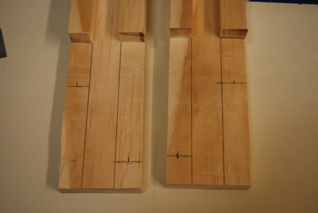
|
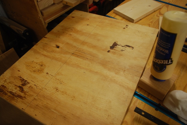
You can see where I drew lines showing the positions of the support and stop posts.
I also drew lines showing the shelf's path.
|
|
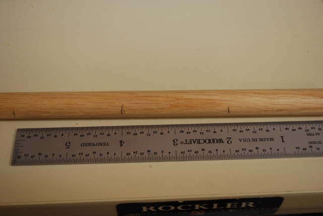
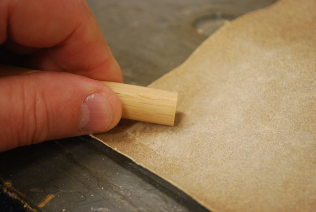
Marked a 1/2" dowell every 2" for bandsawing.
In previous loading shelves, I used 3/8" but decided to try 1/2" this time (I think I'll stick to 3/8").
|
|
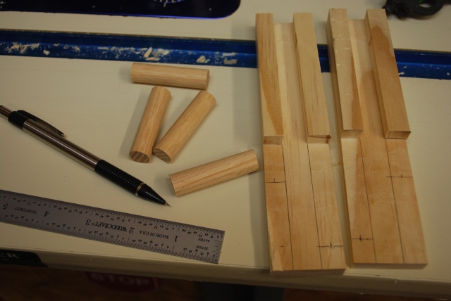
2" dowells cut out beside slides.
|
|
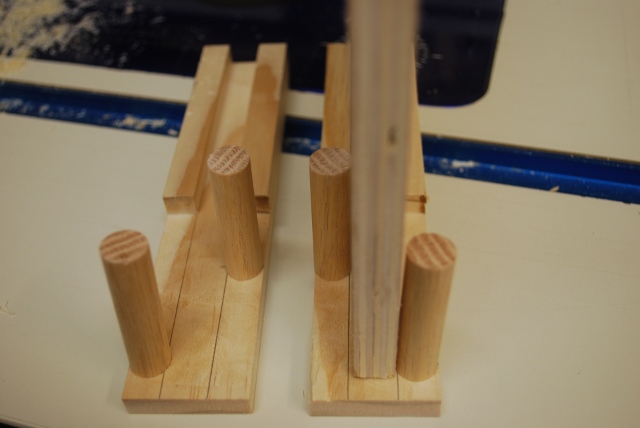
Shelf test fit.
|
|
I used sand paper to put a slight chamfer on each end of the pegs.
|
|
Shelf with front lip (pull) and stop block being glued on.
|
|
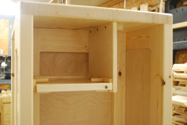
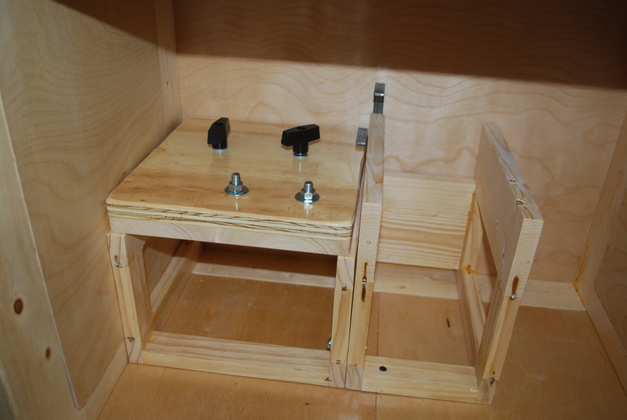
Inside the loading bay, the two support blocks for the loading shelf's side panel glued into the loading bay, top and back.
The loading shelf's side panel will be glued and screwed to these two blocks.
|
|
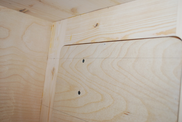
Inside the main bay you can see the two screws holding the loading shelf's back support block (the block is also glued).
The screws used to hold the loading shelf slides and their support are the only screws in the entire bench, all other joints use glue and loose tennons.
You can also see where I've already drawn lines for the two drawer guides.
|
|
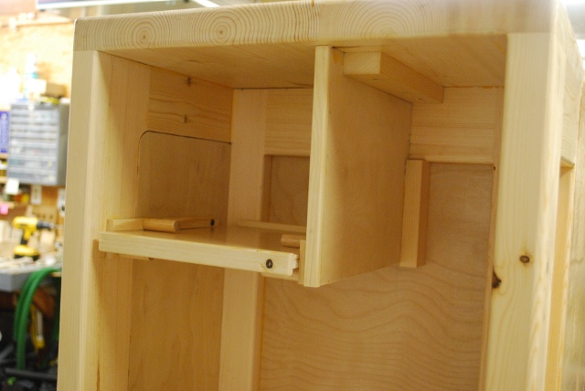
Loading shelf's side panel and shelf slides being glued in.
|
|
Another shot of the loading shelf supports.
|
|
The loading shelf itself showing front pull and rear stop block.
|
|
Close up of the front shelf pull.
This also makes the front of the shelf a little nicer (no raw edge of plywood exposed).
|
|
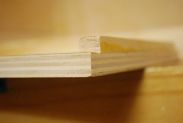
Close up of the stop block and back end of shelf, note the relief (space) between the end of the stop block and side of the shelf, this leaves room for the guides.
|
|
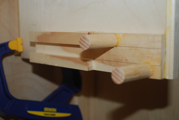
Close up of rear shelf slide.
The slide is used as a guide to drill holes for the back end of the pegs so they are glued into the side panel.
Note no screws needed here, I am able to clamp the slide to the support panel while the glue dries.
|
|
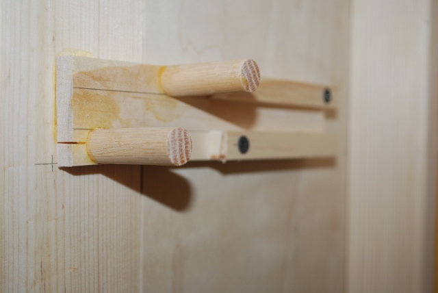
Same goes for front slide, pegs are glued into the bench's frame.
You can also see the two screws that help hold the slide on while glue sets.
|
|
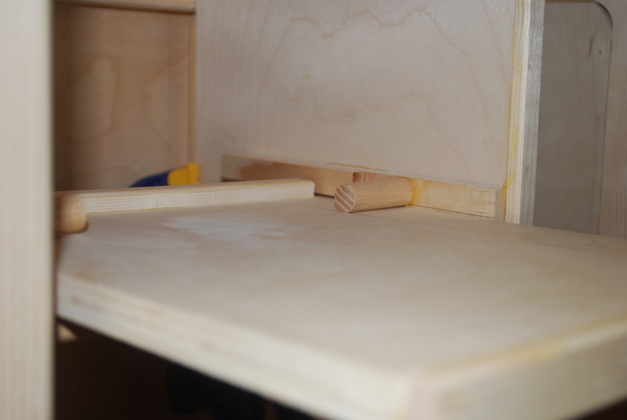
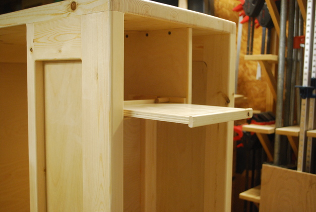
Shelf installed, you can see the stop block and the stop peg.
You can also see the cap strip I glued to the front of the support panel, just makes it look a little better.
|
|
See how the stop block hits the stop peg when the shelf is fully extended.
This keeps the user from pulling it all the way out of the slides.
|
|
Lifting the front of the shelf lowers the stop block so the shelf can be removed.
I have a little bit of sanding to do on the slides so there will be more clearance after I paint.
|
Loading shelf page (with link to construction).
|
Cabinetsides painted.
You can see the subtle color difference between pine and birch (panels)
|
|
Loading bay end, painted.
|
|
Loading shelf top side.
|
|
Closer shot of loading bay after painting.
|
|
Back side painted.
|
|
Back and left end.
Again the flash shows the subtle color difference between pine and birch with poly.
|
|
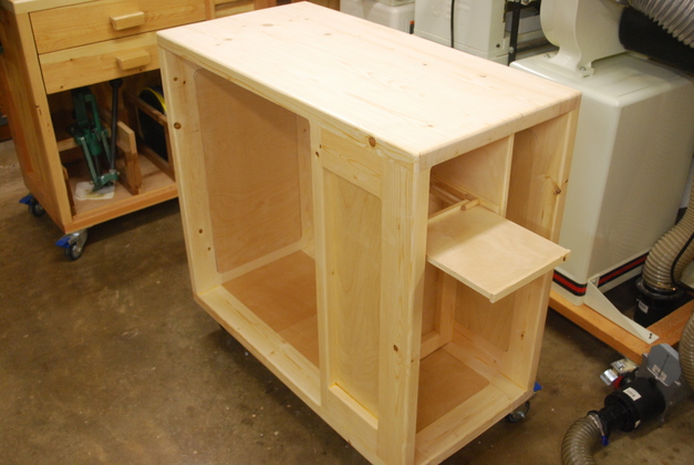
Loading shelf in cabinet.
See how much nicer the front edge of the shelf and support panel look with cap strips.
|
|
View from the rear.
|
|
Lodaing shelf extended.
|
|
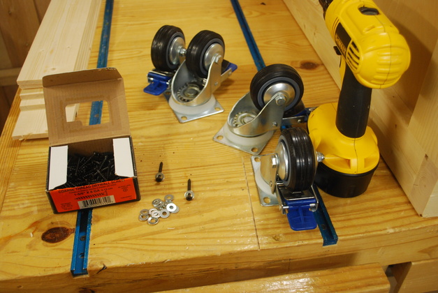
Ready to install casters.
|
|
Casters installed.
|
|
On its own wheels.
You can see the original loading bench on the left.
|
Drawers
|
Drawer backs and sides cut to length.
Each one will be resawed so I'll have twice as many parts: 2 Drawers = 4 sides, 2 backs.
|
|
Resaw lines drawn.
|
|
Resawing and jointing done.
|
|
All parts (except bottom) for one drawer, sides on top, back, then front all rabbeted.
The small rabbets along the edge are for the bottom, the rabbet across the end of the front is to hide the slides.
|
|
Dovetailing, you can see a side and back clamped in the dovetail jig, the other side and front are on the bench behind the jig.
|
|
Dovetails cut.
When your bit gets old and not as sharp you get a lot of ragged edges.
Porter Cable discontinued this model and won't even sell parts for it.
I've made many many drawers with this jig.
I trim these with my pocket knife before gluing.
|
|
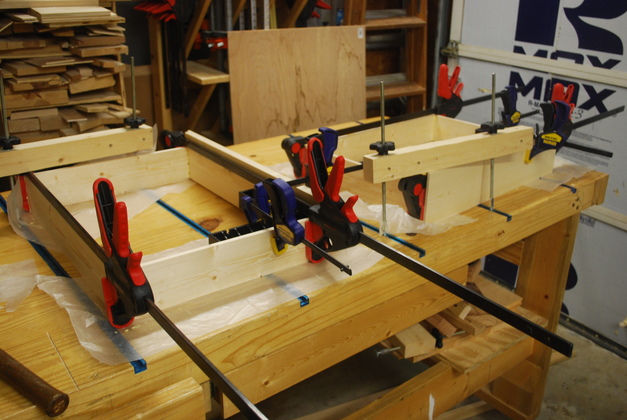
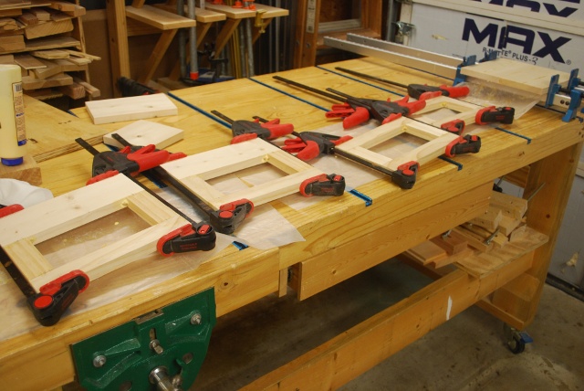
Drawer frames glued, in the clamps.
You can just see the ClampIt in the right front corner, keeping the frame square until the glue sets.
|
|
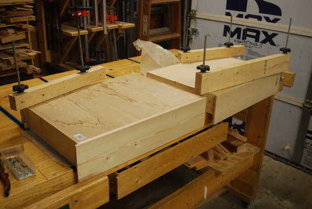
Frame glue set, bottoms being glued in.
I always nail the bottoms in, with wire nails, after I place glue in the rabbets, this is much easier than clamping the bottom as it dries.
The big tee clamps are there to make sure the drawer stays flat on the table (so its square when finished).
|
|
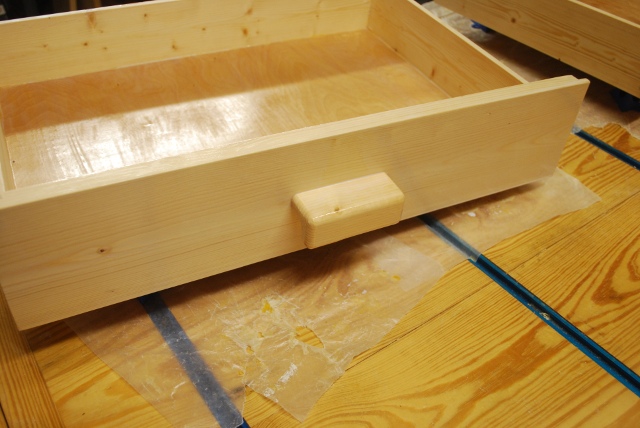
Ready to sand, install handles, then paint.
|
|
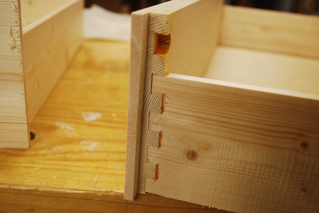
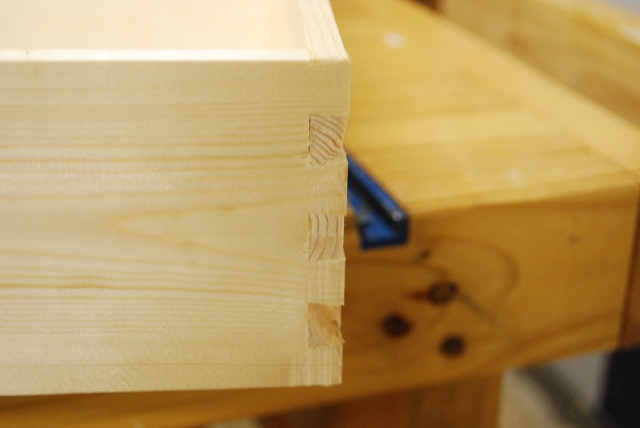
Front dovetail.
Note the drawer front end rabbet will conceal the slides.
|
|
Rear corner dovetail.
|
|
Sanded, handles installed, drawer bottom, sides and front painted.
|
|
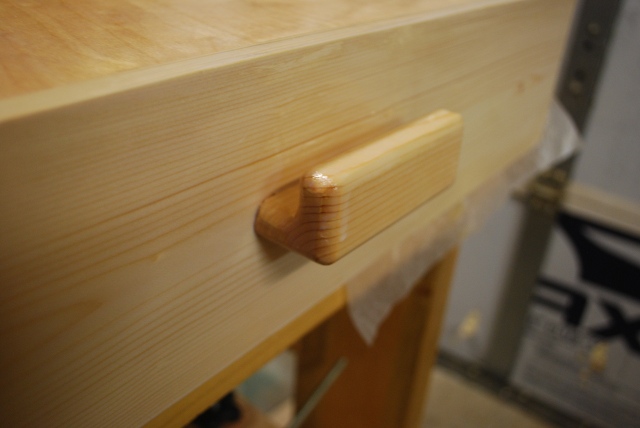
Close up of one of my handles, upside down.
|
|
Top and inside painted.
|
|
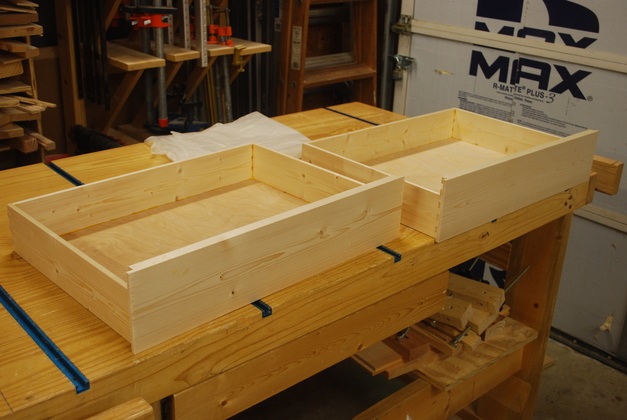
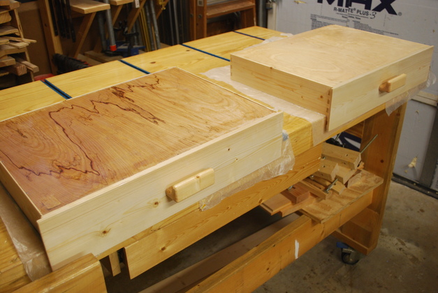
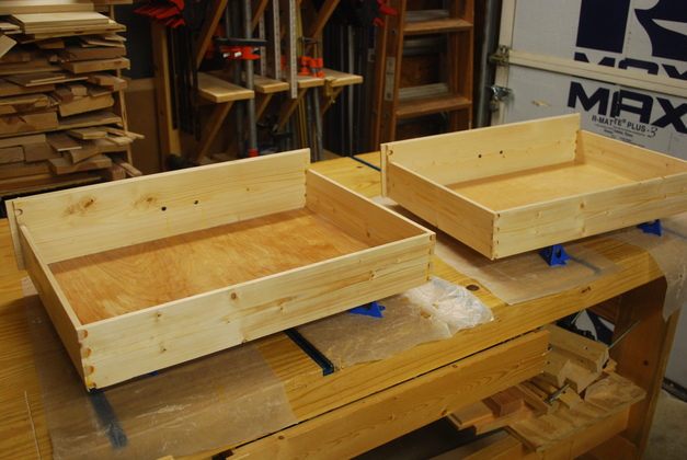
One of the new drawers, ready for final sand and one more coat of paint on the front.
|
|
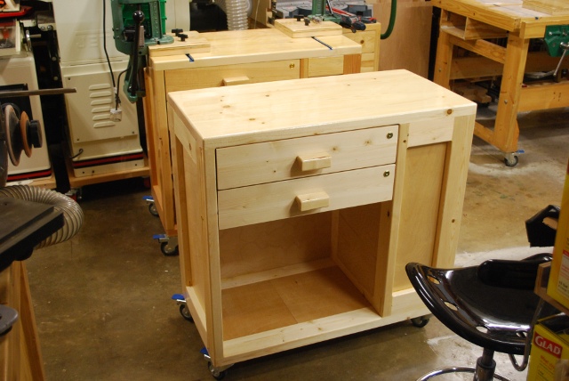
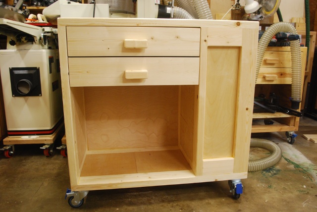
Drawers installed.
|
|
|
Drawers and loading shelf open.
You can see my original loading bench in the background.
Next, paint the top, install tee tracks and drawer locks, then make the press rack and a press base.
|
Metal Work for a Loading Bench
|
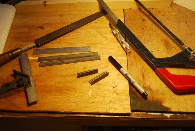
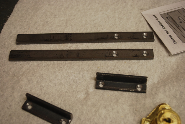
Flat strap for press rack clips and angles for lock strikers cut to length.
|
|
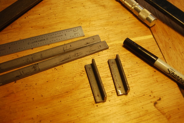
Closer look at strap and angles marked for holes.
|
|
Press rack clip straps and lock striker angles drilled and countersunk.
|
|
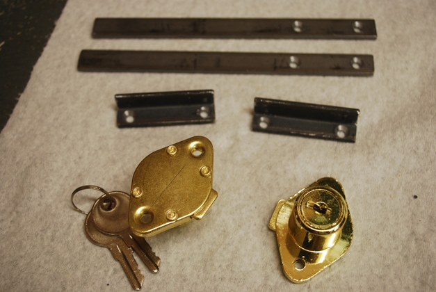
Locks and stikers.
|
|
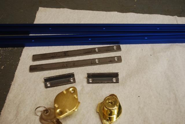
Tee track cut to length, along with drilled straps and angles.
|
Press Storage Rack
|
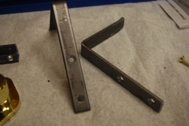
Press rack clips bent.
Note slight up (about 15°) up bend at end to make it easier to slide press base onto rack without hitting end of clip.
I'll spray a little clear Krylon on the clips and angles before installing.
See pics above for more pics of clips before they're bent.
Or, go to my Press Rack Page.
|
|
Press rack parts cut and laid out for marking.
|
|
Loose tennon slots cut, ready to glue.
|
|
All frames (and a press base) in glue clamps.
|
|
Press rack frame pieces glued.
Laid out ready to mark for back frame piece slotting.
|
|
Press rack low side, slotted for biscuits.
|
|
Low side in clamps, note the ClampIts.
|
|
High side in clamps, rear view.
|
|
Quarter view.
|
|
Low and high racks glued, ready to sand and attach to each other, then paint.
|
|
Back view.
|
|
Two racks, side by side, as they will be inte storage bay.
Note I added a crossbar base at the front to keep things square.
|
|
Quarter front view.
|
|
Back view of both racks.
|
|
After one coat of poly, upside down (I always paint the bottom first).
|
|
Press racks clamped together, ready to drill attachment holes.
The two racks will be held together by 1/4-20 bolts and tee nuts.
|
|
Attachment bolts installed, you can see the 1/4-20 round heads and washers on the low side.
|
|
Tee nuts on high side.
|
|
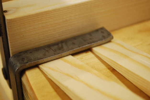
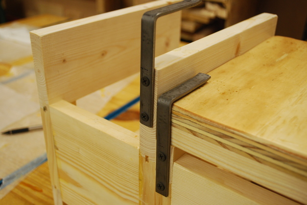
Press base clips on low side, shimmed up for about 1/8" clearance.
|
|
Both clips installed.
You can see an undrilled press base used for spacing.
|
|
You can just see the wall board screws holding them in.
|
|
Press rack installed in loading bench main bay.
|
|
A little closer look.
|
Press Base
|
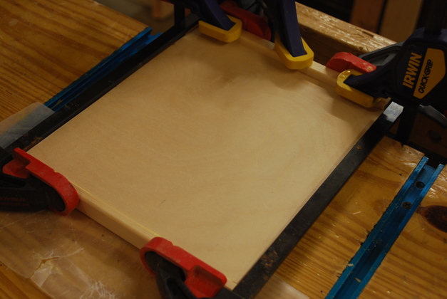
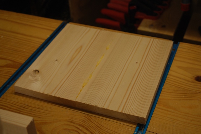
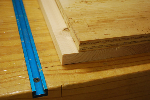
A piece of 3/4" plywood marked for 10x10" base.
This will be the top of the press base.
|
|
Two 1x6s, 10" long slotted for jointing.
This makes the bottom of the press base.
|
|
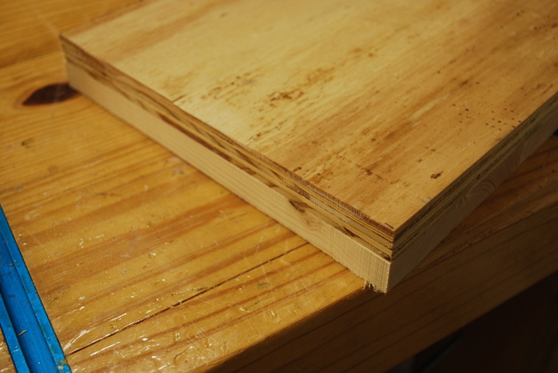
The bottom of the press base after two 1x6 joined (glued).
Next I laminate the bottom to the top.
|
|
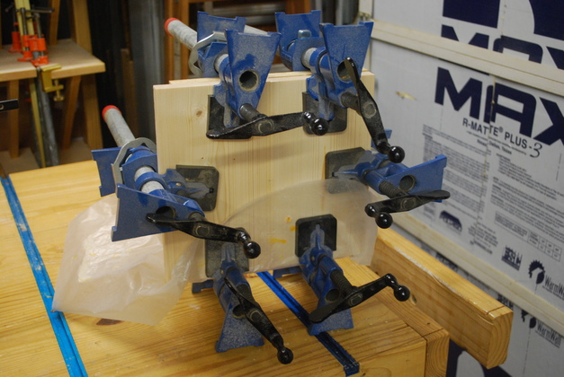
Laminating top to bottom.
Six 500 LB clamps, plenty of pressure.
|
|
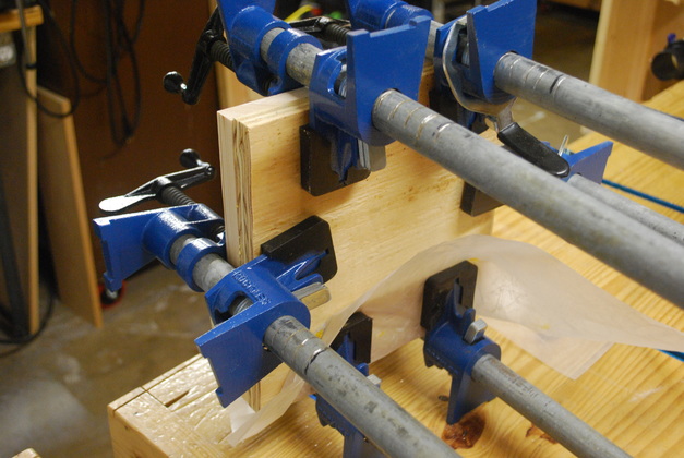
View from rear of lamination process.
|
|
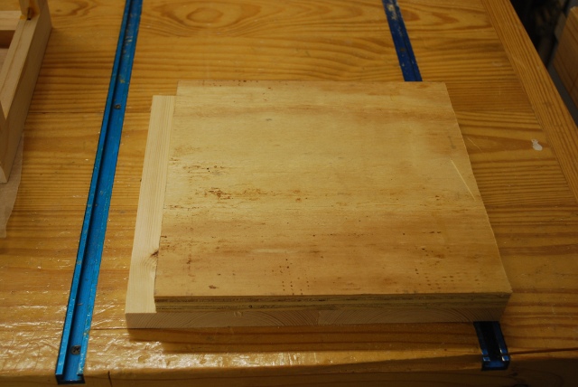
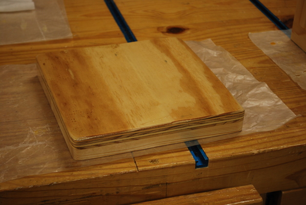
After laminating the top to the bottom.
Note the bottom is wider (two 1x6s are wider than 10").
|
|
Closeup of bottom overhang.
I'll have to cut off the overhang on the bandsaw so I end up with a 10" by 10" square base, 1-1/2" thick.
|
|
After trimming with a bandsaw.
Next I'll put it on the disk sander and smooth the edges and round the corners.
|

|
After sanding, rounding edges and one coat of poly on the bottom.
Go Here to see my Press Base Page.
|
|
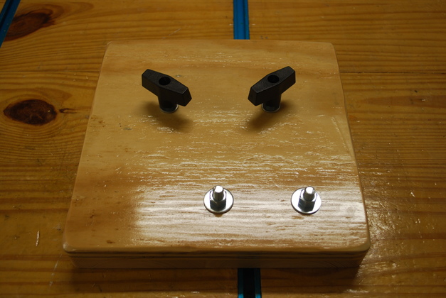
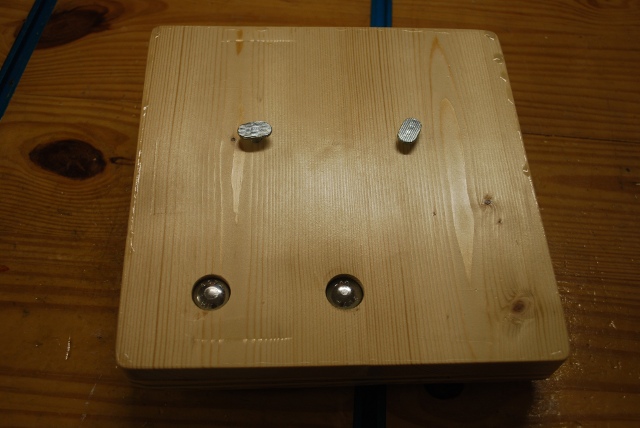
Final press base, painted ready to drill.
|
|
Drilled with 5/16" tee bolts and 3/8" carriage bolts for the press.
|
|
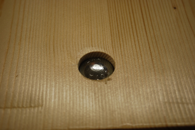
Under side showing bottom of tee bolts and carriage bolt heads in counter bores.
|
|
Closer look at carriage bolt head in counter bore.
|
Drawer Locks
|
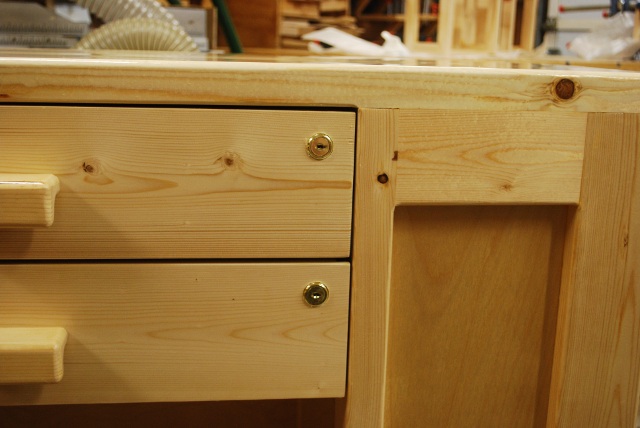
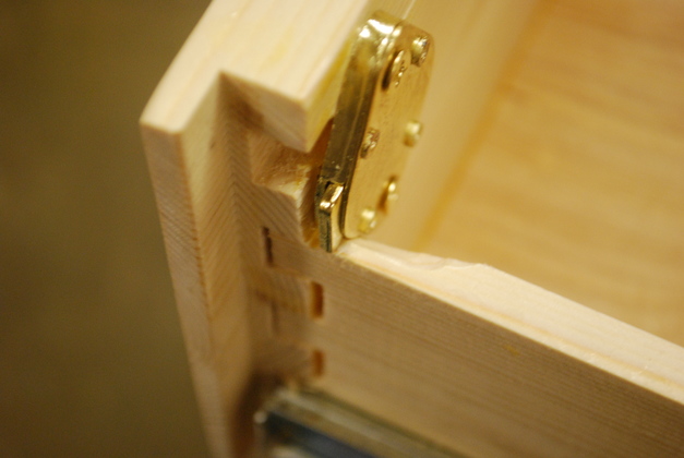
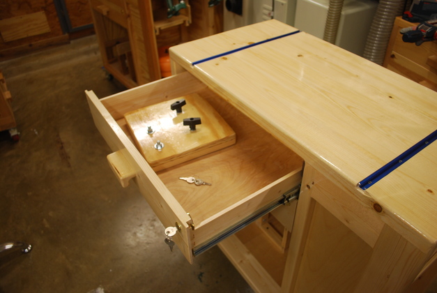
Drawer locks installed.
|
|
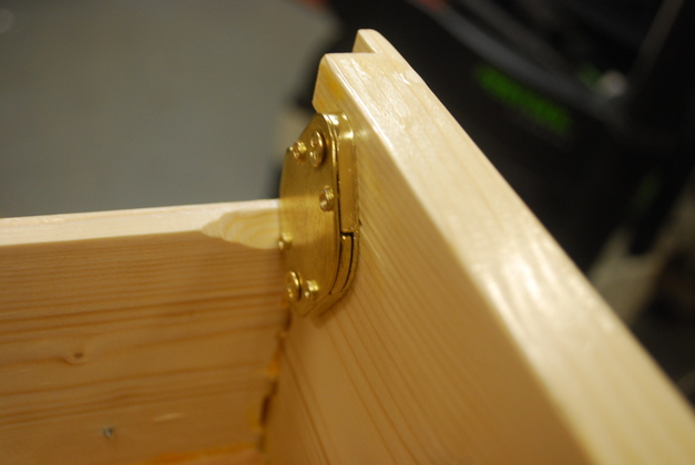
Backside of drawer lock, note I had to bevel the top of the drawer side to allow the lock to slide in it's hole.
|
|
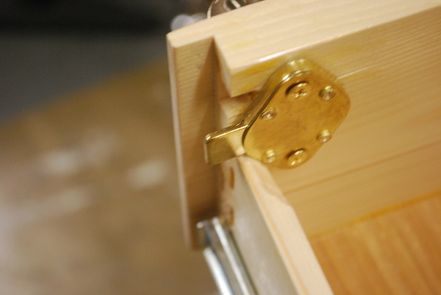
Lock with bolt retracted, its flush with drawer side.
|
|
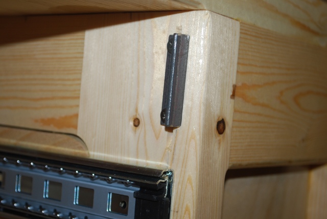
Drawer lock with bolt extended, it should engage the striker bar solidly (about 1/4").
|
|
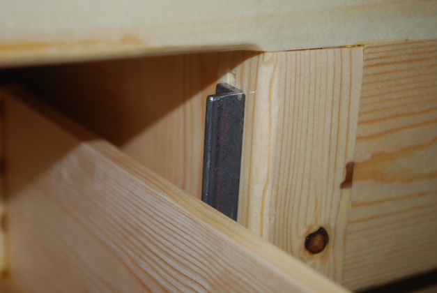
Striker bar above drawer edge.
|
Tee Bar Install
|
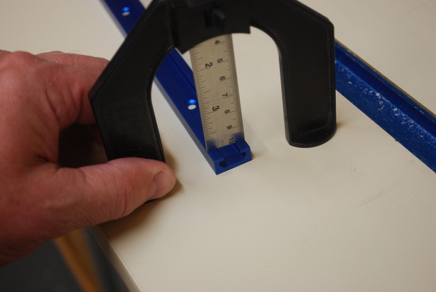
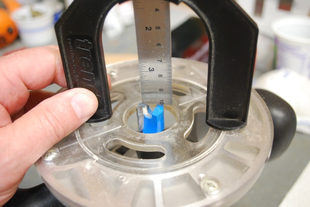
I copy the height of the tee bar with my router depth guage.
|
|
After opening it up about 1/32" extra, I set the height of the mortising bit with the guage.
|
|
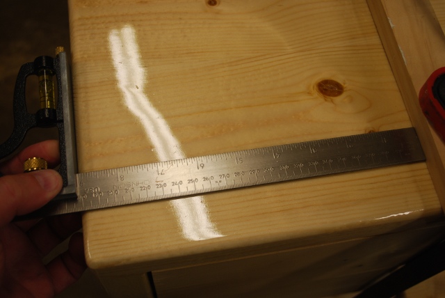
I set the guide bar 9" from the edge of the table.
That should make the center of the tee bar 6" from the edge.
|
|
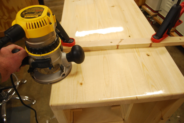
With guide bar firmly clamped down, I am about to make the first cut, left to right.
After all the work on this bench, this is NOT the time to blow a measurement, I checked these 3 times.
|
|
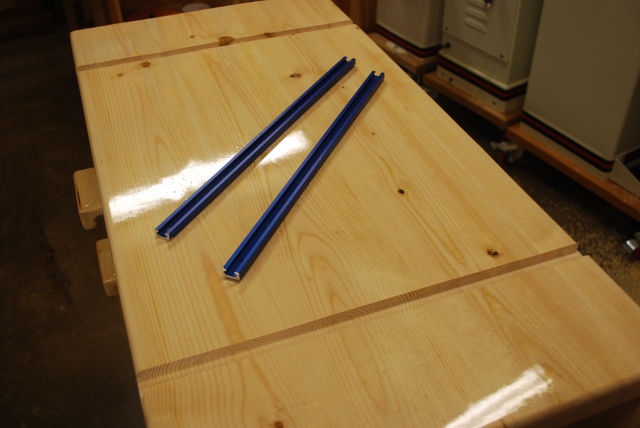
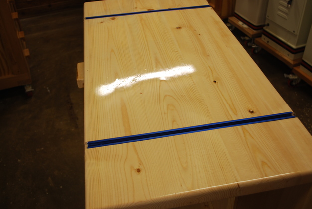
Moritses for tbars cut (nice and straight), ready to install.
|
|
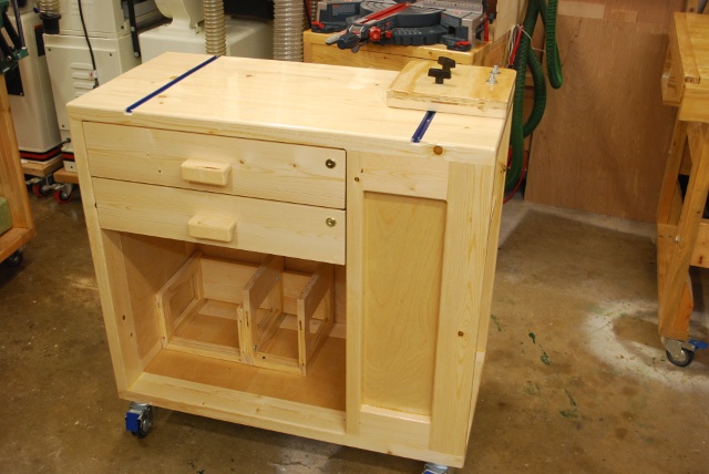
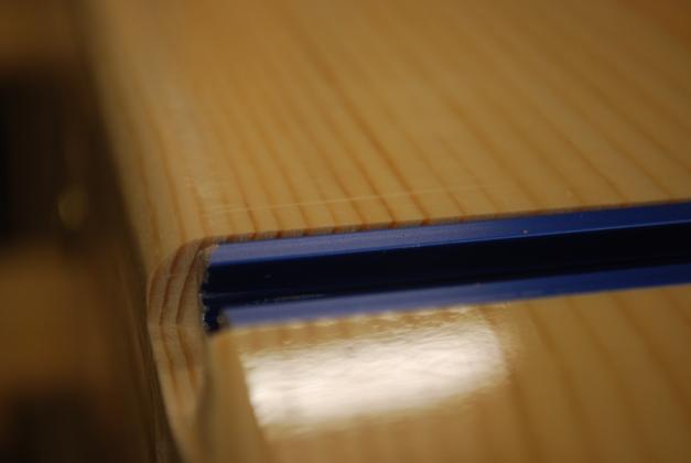
Tbars installed, the bench is finished.
|
|
You can see tbar is about 1/32" below the bench top and 1/4" from the end.
|
Final and New Vs Old
|
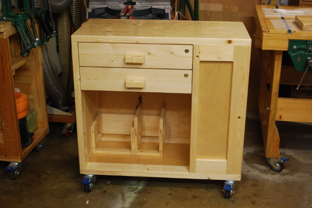
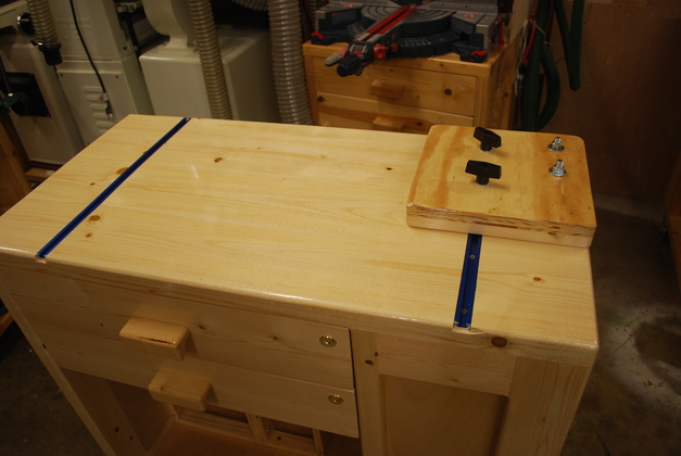
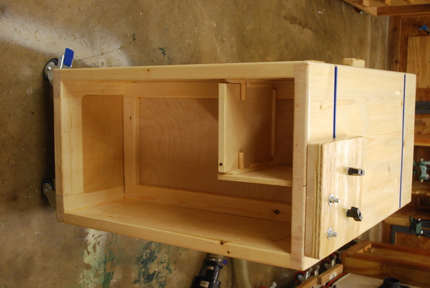
Finished bench with a press base installed.
|
|
Loading bay with press base installed.
|
|
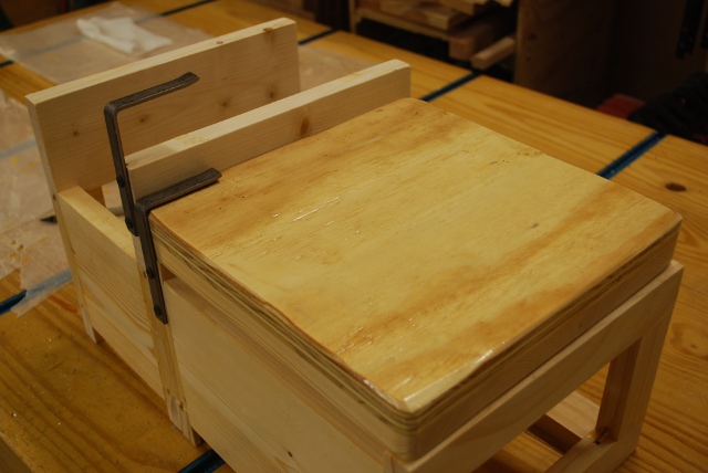
The way I move them, with press base in drawer (the drawer will be locked while moving).
|
|
Heres what the press rack looks like with a press base on the low side.
|
|
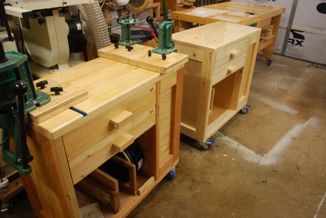
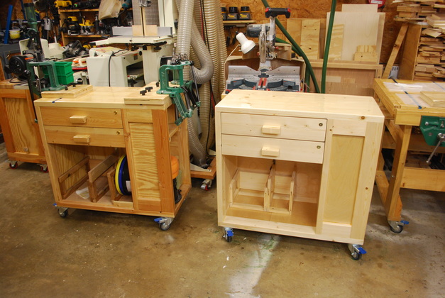
New vs Old: my original bench on the left and the new bench on the right.
The water based polyeurethane apparantly yellows a bit as it ages, the original bech is about 3 years old (and has loaded many thousands of rounds).
This is just before I installed John's tee tracks.
|
|
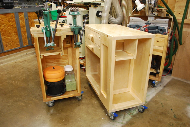
Loading bay view of both benches.
|