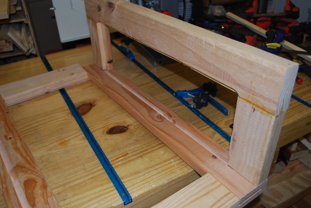
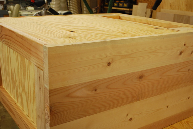
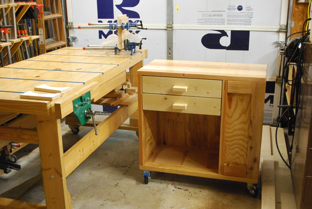
Kyle's loading bench nearing completion,
still lacks drawer locks and tee tracks.
|
|
Kyle's Loading Bench
|
01/07/13: Origin.
Grandson Kyle, a Dallas Police Officer who we have taught to reload his practice ammo (9mm and 357SIG).
With 2 little boys at home and his wife being a nurse (with a very hectic scedule of her own) he only has time in sporadic 2 or 3 hour chunks of time, which only allows him to reload.
As everybody knows, all law enforcement officers must practice with their firearms frequently, and that requires ammo.
He has been using my loading bench and press, but wants to be on his own, so I am assembling this bench for him.
Kyle wanted to help in order to learn a little woodworking, but between work and raising 2 boys he has very little time.
Building a loading bench is a time consuming job (about 3 weeks, 7 days per week), so I thought I could do something smaller with Kyle to let him get his feet wet (or sawdusty).
When I started, I already had the top joined and the frame pieces assembled, so here is the rest of the tale.
NEW==>
I decided to make the floors of the two bays an integral part of, and flush with, the frame, instead of just attaching them later.
I added slots and rabbets for the floor of each bay (loading and main).
Putting the main bay floor in slots and rabbets (making it flush with the frame floor), requires an extra support in the center of the main bay.
I cut a 1x4 and drilled screw pockets on each edge of each end, then glued and screwed the support in the center of the main bay floor.
Unfortunately, I was so rushed for time when I finished Kyle's bench, I didn't get any pics of the completely finished bench.
|
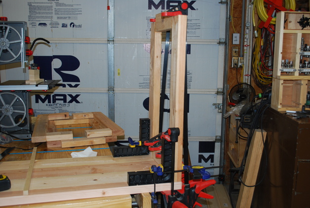
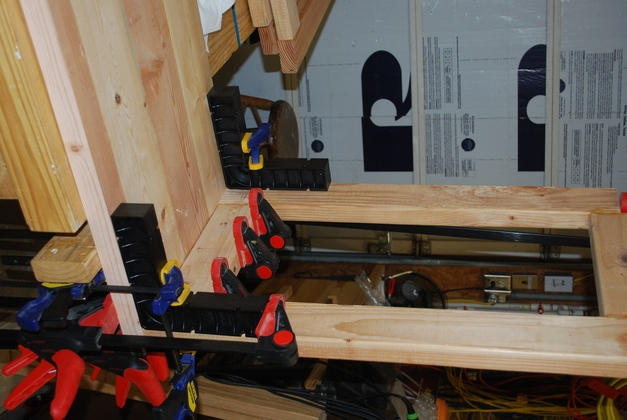
The left end vertical gets glued on to the top.
|
|
A closer look at keeping the vertical square with the top.
I use Rockler's Clampits.
|
|
All the verticals for the loading bay (right end).
|
|
You can see the slots cut in the center vertical for the loading bay's inset panels.
|
|
The bottom frame piece (stringers) gets glued together.
|
|
Bar clamped on to cut floor slot in center vertical.
This vertical gets floor slots cut on both sides.
|
|
A closer look at the floor slot on the left, the guide bar, and inset panel slot on the front side of the center vertical.
|
|
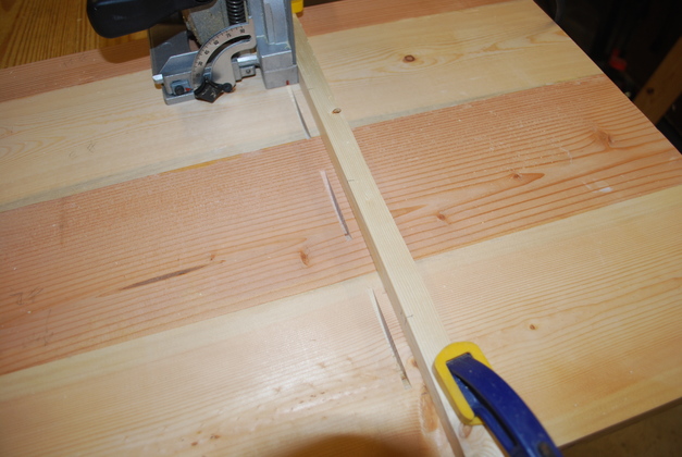
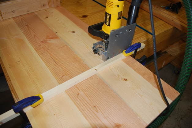
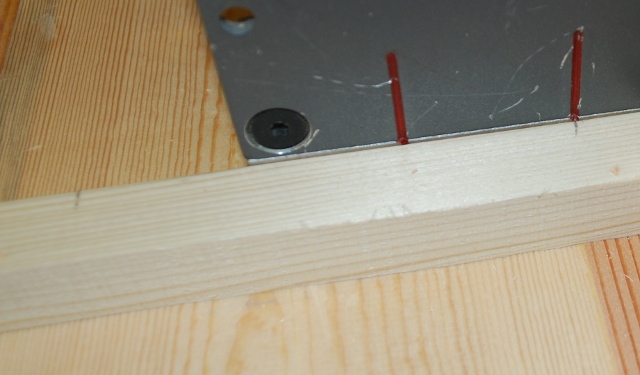
Biscuit cutter being used to cut top slots for center vertical.
|
|
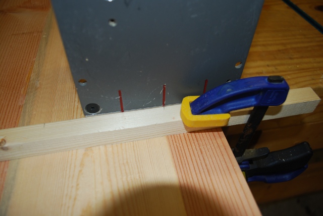
Close up of mark alignment with buscuit cutter.
I initially marked 2" from each side of the bench top, then every 4" apart.
This (Dewalt biscuit jointer) cuts slots 3/8" above the bottom plate, I wanted the center vertical 10" from the right end, with biscuits in the center (3/4" from either side), so I clamped the bar 10-3/8" from the right end and cut the biscuit slots.
|
|
A little closer view of tick marks on alignment bar.
Using a bar makes it easy to have all the slots aligned with each other.
|
|
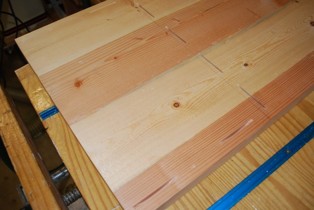
The biscuit slots in the loading bay end of the top (under side).
You can see the alignment mark 3/8" from the center of the slots, this is what the bar in the above pics was alligned with.
|
|
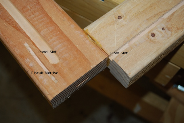
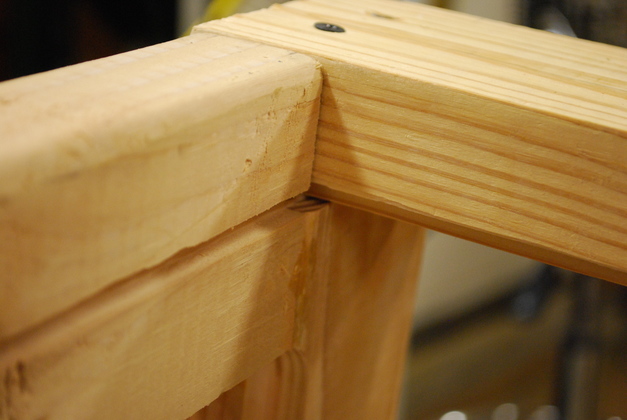
On this test fit of the front, back loading bay frame pieces to the center vertical, you can see how the inset panel rabbet (1/2") lines up with the slot.
|
|
A full view of the front loading bay frame piece being test fit.
|
|
One of the biscuit slots for the loading bay front frame piece (far left), on the left side of the 1/2" inset panel slot.
You can also see the 1/4" floor panel slot.
|
|
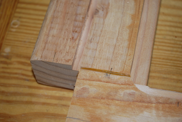
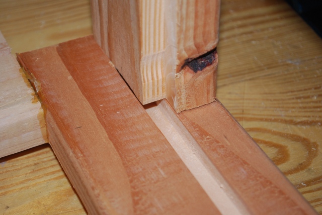
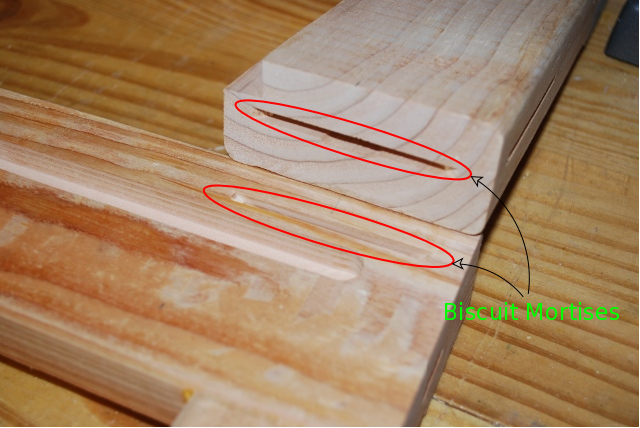
Loading bay frame piece and center vertical showing how inset panel and biscuit align.
Biscuit mortises are in the red ovals.
The frame piece is 1-1/2" thick with a 1/2" by 1/2" rabbet for the inset panel.
I cut the slot in the center vertical (1/2" by 1/2") 1" from the outside edge, that makes the rabbet and the slot line up.
|
|
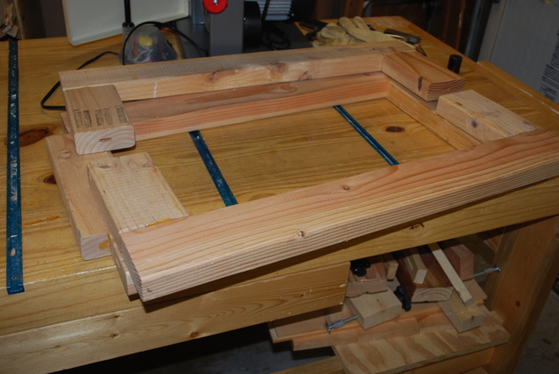
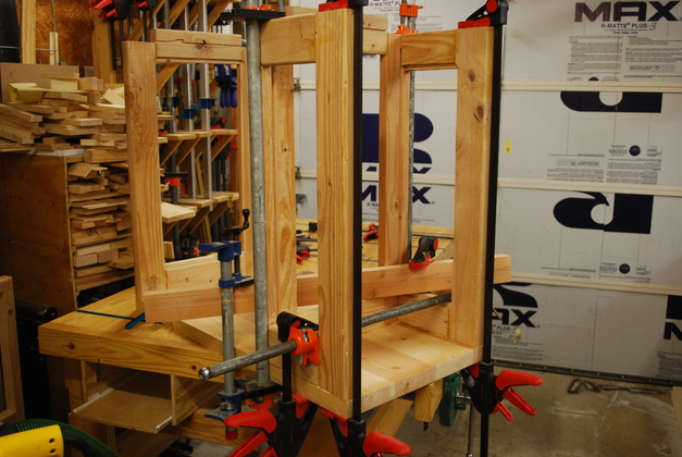
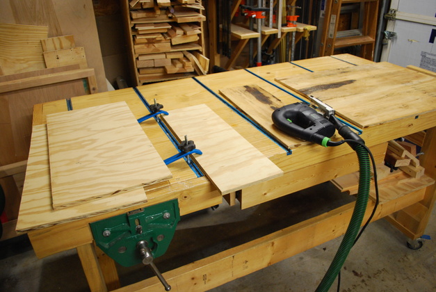
Loading bay frame being glued on.
Note I clamp everything to the work bench top, since its very flat.
|
|
Major frame parts glued on.
Viewed upside down.
|
|
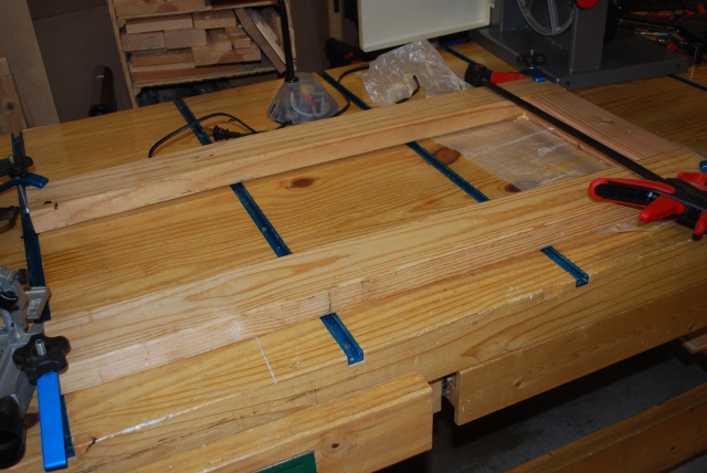
This is something new, I originally didn't make any provisions in the frame for a floor of the two bays, I just glued it on top of the frame pieces.
But this time I cut rabbets in the bottom stringers and slots in the vertical frame pieces for a 1/4" plywood floor for both bays.
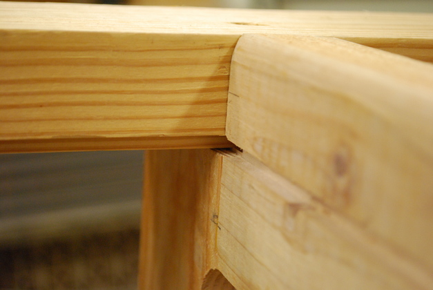
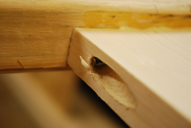
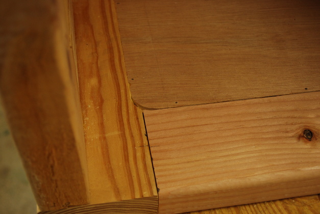
Here, from the bottom, you can see the slot in the left end vertical, and it's matching rabbet in the stringer.
|
|
Slot in one side of the center vertical, and rabbet in stringer.
The center vertical has slots in both sides for both bays.
|
|
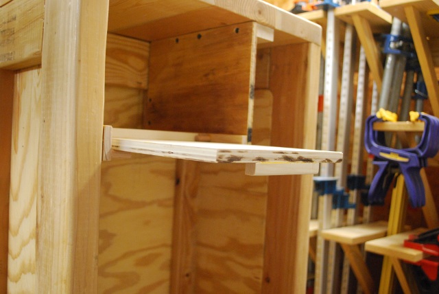
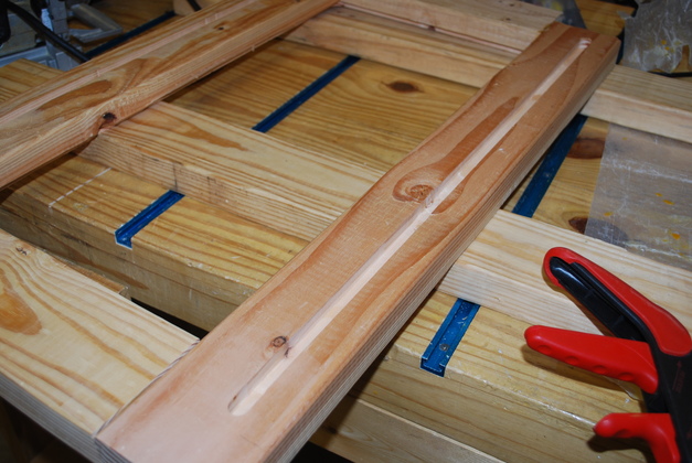
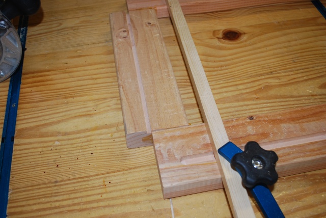
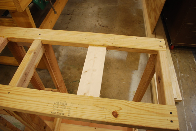
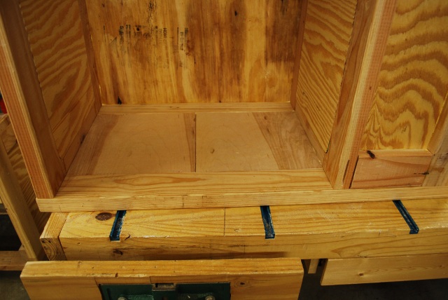
The floor of the main bay will need an extra brace, so I marked the center of the bay area, cut a 1x4 and here I am doing a trial fit and mark it's position.
|
|
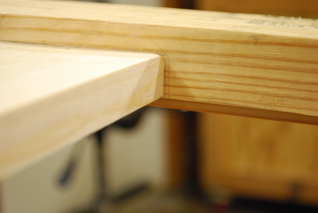
The main bay center floor support (from the bottom) see how it's top (bottom in the pic) matches the rabbet in the stringer.
|
|
I used the Kreg pocket kit to drill edge screws along with glue to hold the brace in.
|
|
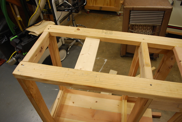
From the bottom, frame with new brace glued/screwed in.
|
|
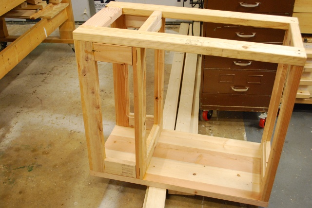
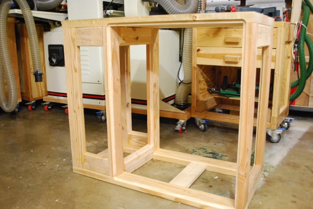
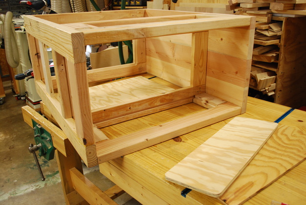
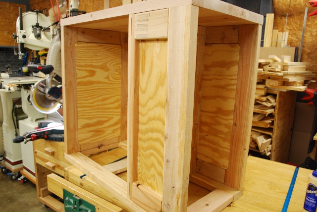
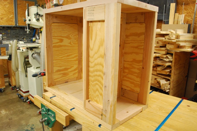
Complete frame, upright, from the back, showing new floor brace.
You can see the rabbet cut around the rear of the main bay for the ply panel.
Panels are next.
|
|
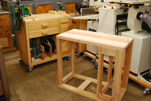
New frame in right foreground with original loading bench, in left background.
|
|
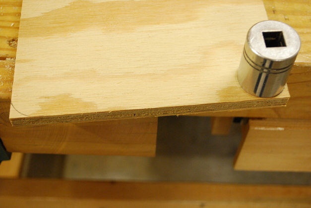
Panels cut out.
Now the corners must be rounded off to match the rabbets.
|
|
I use a socket as a template for rounding, nice thing about socket sets is, I have a template for almost any curve.
|
|
All corners rounded, now I'm test fitting.
|
|
Ready to glue, I put glue on the rabbets (and slots), then I use 1" long wire nails to hold the panel while the glue sets up.
|
|
Back and sides glued in.
Note back of cabinet is flat.
|
|
All panels glued in, now the floors.
|
|
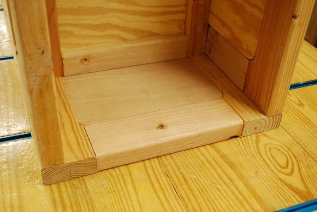
Floor panels glued into main bay.
|
|
Floor panel glued into loading bay.
|
|
Closer look at wire nails holding panel while glue sets in loading bay.
|
|
All panels and floors glued in.
|
|
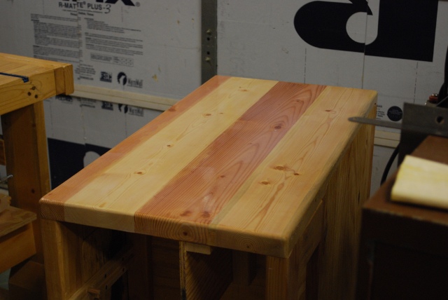
Top painted first coat.
It will need about 5 coats to get the desired finish, the last two will be heavy coats.
I sanded the top with 320 grit before painting and again after the first and second coats.
|
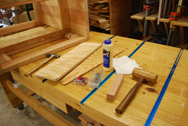
Next I build the drawers, a press base, and a set of tumbler clamps.
|
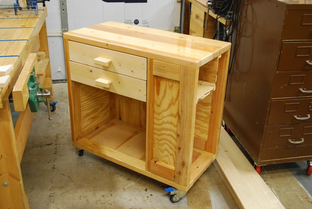
Heres Kyle's bench with the drawers installed.
On the workbench beside the loading bench, you can see a press base in the glue clamps, and a set of tumbler clamps, cut out, on the near corner.
|
Next: Install Tee Tracks and Drawer Locks.