|
|
|
Updraft Dust Valves
| |
|
|
|
|
Updraft Dust Valves
| |
| Main Dust Collection Page | New Plenum | Dust Valves | Final Install |
| Plywood Ripper Page | Diagram | Pressure Calculation Vectors | Dual 4" Ext |
| Single. 4" Extension | 6" Updraft Valve |
Valve Design Goal: air flow tends to keep the valve open while vacuum keeps the valve closed.
The valve boxes eliminate the need for blast gates on the end of each hose.
The valve boxes are made of 1/2" birch plywood, the valve flapper will be 3/16" thick birch plywood.
The fronts of the plenum and valve boxes are removable, for cleaning, with a felt gasket and be held on with #8 flat head screws.
There are felt gasket seats under the valve flapper and between the valve box and plenum.
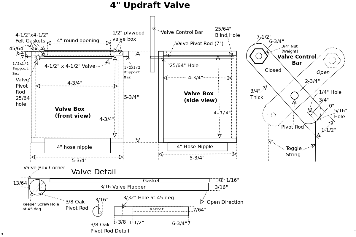
The valve has a 3/8" oak pivot rod with a 1" x 2" valve control bar on the outer end, attached with a pin.
The valve flapper is glued into a rabbet routed into the pivot bar.
The rabbet routed into the pivot rod is positioned so that when the flapper is closed it is flat against the 1/16" gasket at the top of the valve box.
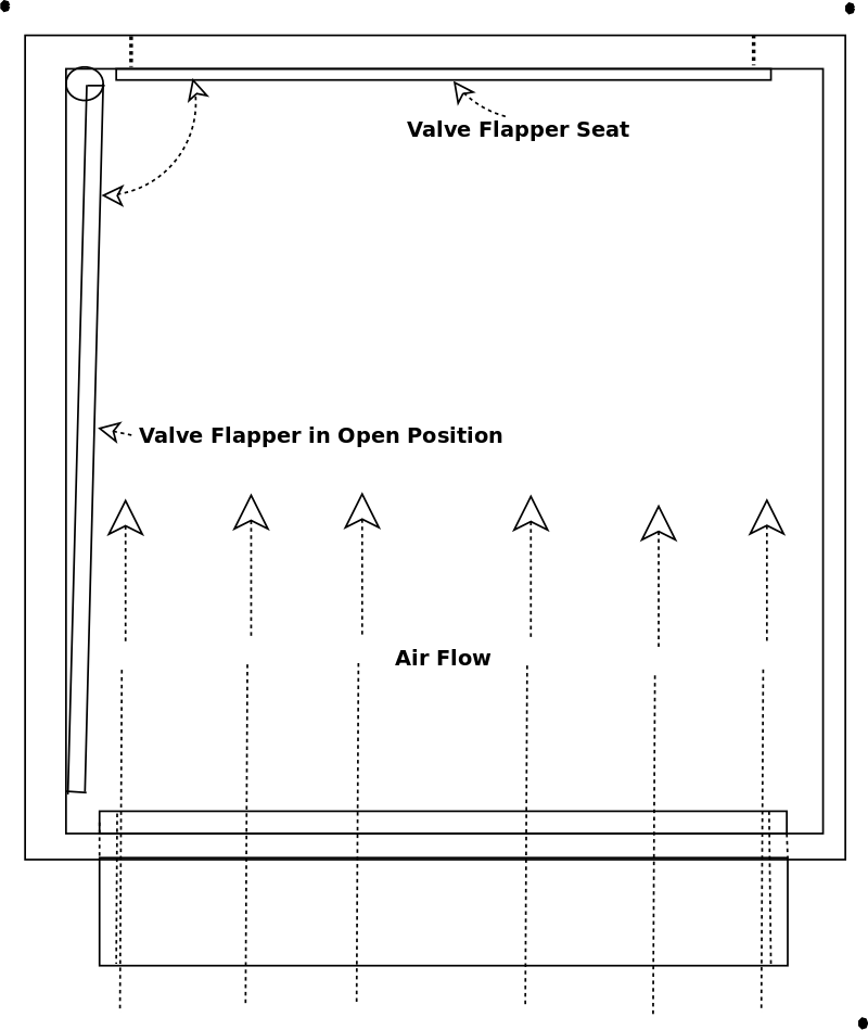
This slight offset of the pivot end of the flapper also means, when the valve is open, it's edge away from the pivot is against the inside of the box, it is slightly angled so the wind pressure tends to help keep it open.
Please see "Updraft Valve Open" diagram.
The valve control bar will sit at 45°, top left when closed and 45° top right when open.
Valves:
The valve boxes will also be made from 1/2" birch plywood painted with polyurethane.
The valve flapper will be 3/16" birch plywood, also painted with polyurethane.
One end of the flapper will be glued to a pivot rod (3/8" round hardwood dowel).
One end of the flapper pivot rod will be anchored in a 25/64" blind hole in the rear of the valve box.
The other end of the pivot rod will proturde through the fron of the valve box through a thrugh 25/64" hole far enough to allow a control bar to he attached.
The control bar will have a large steel nut and bolt as a top wieght and be at a 45° angle with the flapper.
The weight in the top of the control bar, because it is at a 45° angle, will hold a slight pressure against the flapper so that it stays either open or closed.
The valve box will have a sticky-back felt gasket where the flapper closes to the top of the valve box.
When the flapper is open the control arm's weight, will push it against the side of the box (almost vertically), out of the way of the air and chip flow so there will be minimal pressure on the flapper.
The fronts of the plenum and valve boxes will be removable, for cleaning, with a felt gasket and be held on with #8 flat head screws.
The valve will have a 3/8" oak pivot rod with a 1" x 2" valve control bar on the outer end, attached with a pin.
The valve flapper will be glued into a slot routed into the pivot bar.
The valve control bar will sit at 45°, top left when closed and 45° top right when open.
The valve control bar will have a weight (3/4" nut = 1.8oz.), imbedded into the upper end, 4" from the pivot point.
The weight will keep the valve in either the open or closed position (gravity CAN be your friend).
The toggle action of the valve control arms also acts a a kind of memory so when the vacuum is off the valves stay wherever they were placed.
A quick tug on the toggle string (2" from pivot point) will toggle the vale open or closed (opposite position)
The valves are modular, that is, each can be removed and dissasembled, for repair or replacement, I could even block one off if it was necessary.
The valve control bar has a weight (3/4" nut = 1.8oz.), imbedded into the upper end, 4" from the pivot point.
The weight will keep the valve in either the open or closed position (gravity CAN be your friend).
The toggle action of the valve control arms also acts as a kind of memory so when the vacuum is off the valves stay wherever they were placed.
A quick tug on the toggle string (2" from pivot point) will toggle the vale open or closed (opposite position)
The valves are modular, that is, each can be removed and dissasembled, for repair or replacement, I could even block one off if it was necessary.
When vacuum is applied (blower running) the pressure helps keep the valves closed and when open the wind velocity simply bypasses the valve (note valve diagram).
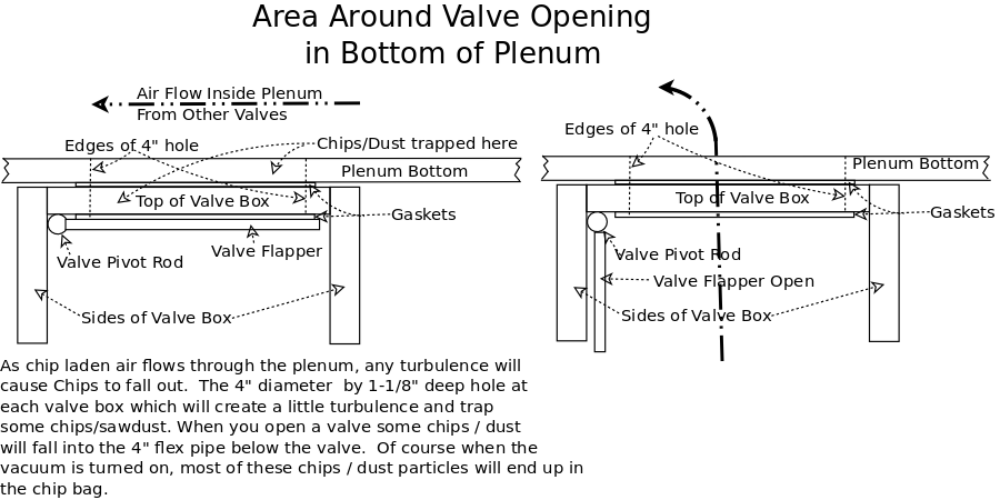
The valve flappers are 4-1/2" square and have a 4" (12.57 in²) round opening.
The valve box's interior will be 4-3/4" square (21.36 in;² when open) (4" hose has 12.56 in²) so wind velociy will drop slightly inside the valve, but this is vertically oriented, meaning no sawdust buildup.
Here is a link to a quick diagram explaining where chips / dust will be trapped.
I need to keep the cross sectional areas (CA) about equal so wind velocities will be fairly constant.
That said, the main plenum and riser is the same CA (cross sectional area) as a 6" round duct, the valve boxes are near the CA of a 4" hose, so I can have two valves open at once.
The interior and exterior surfaces of all valves, the plenum, and riser are painted with clear polyeurethane so dust will flow easier.
After using these valves for several years
These are great, easy to use, convenient and I think I have more suction (no reasonable explanation?).
Before, when I started the DC up, the hoses would all contract since the blast gates were at the machine end of each hose (meaning all the 4" hoses were under vacuum), now, nothing moves except the one(s) turned on.
Having all the valves in sight from everywhere in the room is a huge improvement, I don't have to go around looking or feeling behind each machine to see whats open and whats closed.
All in all it makes changing from one machine to another very simple and quick.
12/01/16:
I have had to access one valve, I sucked up a long splinter (about 4-1/2" long) which jammed a valve in the almost open position.
I took the hose off the bottom, reached up into the valve housing and pulled the splinter out, voilla, it works great again.
2018
I bought a new Jet JWBS 14-SFX bandsaw which has two 4" dust ports.
So I replaced the 4" valve #2 with a 6" valve, and split it into two 4" hoses for the bandsaw.
I like to dedicate a hose (and valve) to each frequently used machine, it reduces the things I have to do when I move from one machine to another.
The new 6" valve will have a 6" hose to a 6" to dual 4" 'Y' and two 4" hoses to the two ports on the bandsaw.
I also added a 20" extension to the North end of the 4" plenum with two more 4" valves, for the miter saw and the new roll-around router table.
Since I originally designed the ceiling plenum to allow two 4" ports to be open at once, a 6" valve works fine.
| (Click on Diagrams for larger pics) | |
|
|
|
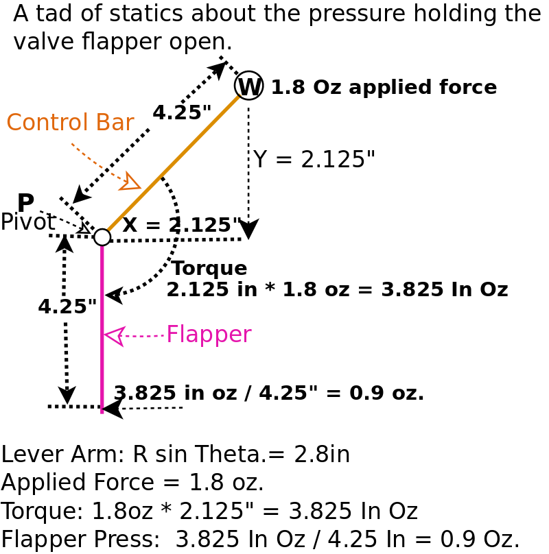
The bar and flapper are a static body (doesn't flex).
Pivot point 'P', weight W is 1.8oz. and bar length is 4.25" at an angle of 45° and the flapper is 4.25" long.
sin 45 = .707 Force Arm = R sin θ = 4.25" * .707 = 2.828". The torque around P is (1.8 oz * Arm) = 2.828 * 1.8 = 3.825 " oz. Flapper is 4.25" long so pressure at the end of the flapper is 5 / 4.25" 1.176 oz. |
|
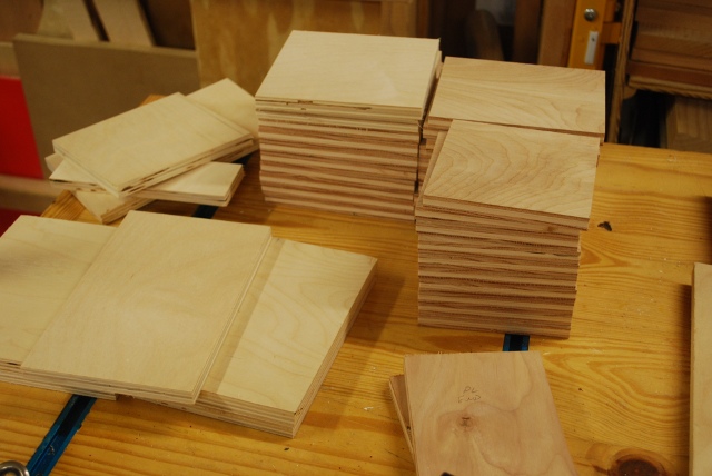
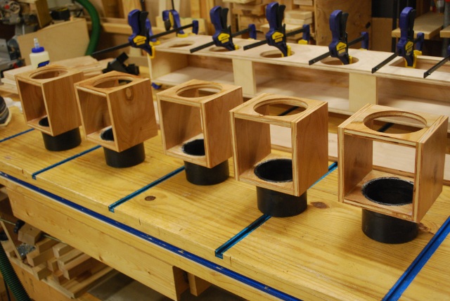
Stacks of valve parts sawed on the Plywood Ripper or table saw.
Note the nice straight edges, good for gluing air tight joints.
|
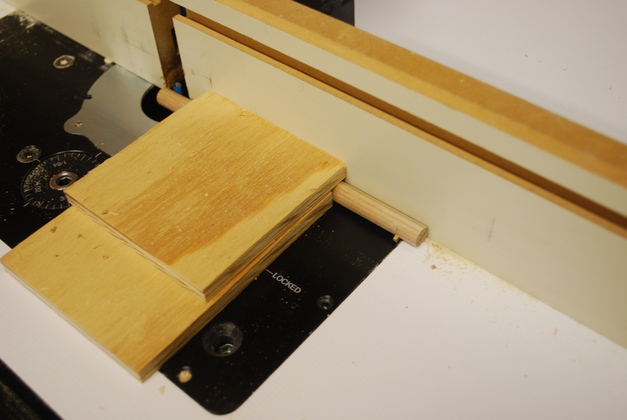
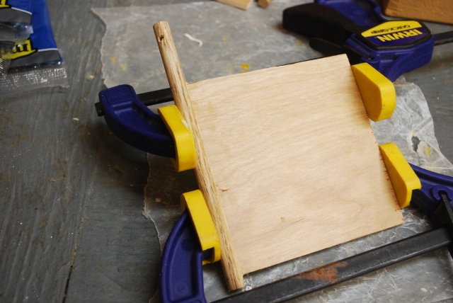
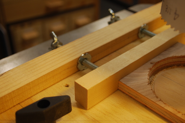
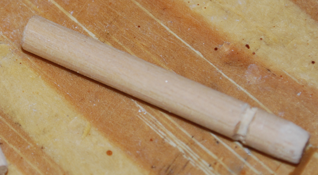
| Two pieces of 3/8" plywood to hold the bar while routing. |
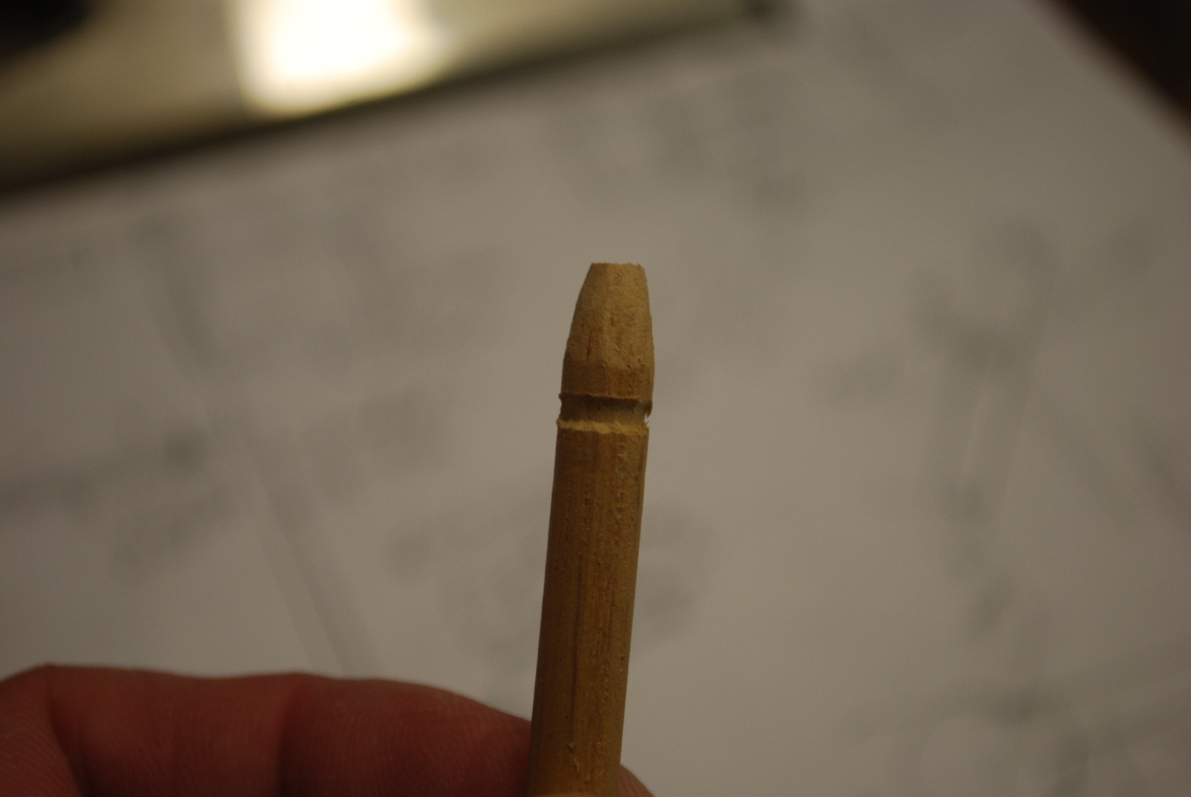
| Close up of the short peg, I keep it against the router lift and fence, while routing, in order to route a straight slot for the flapper and to keep the 45° angle of the hole. |
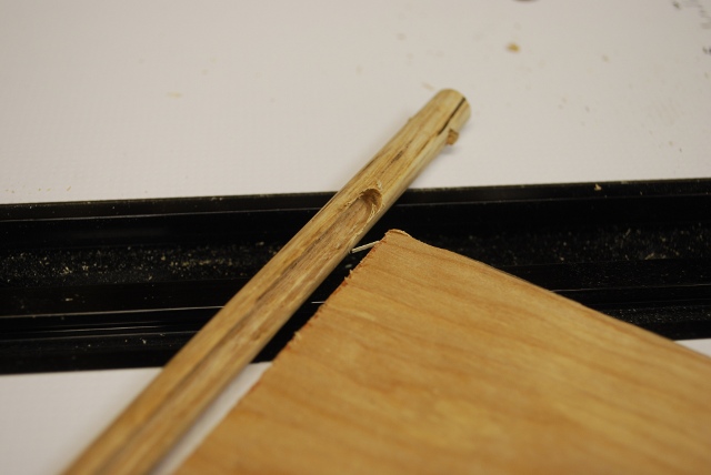
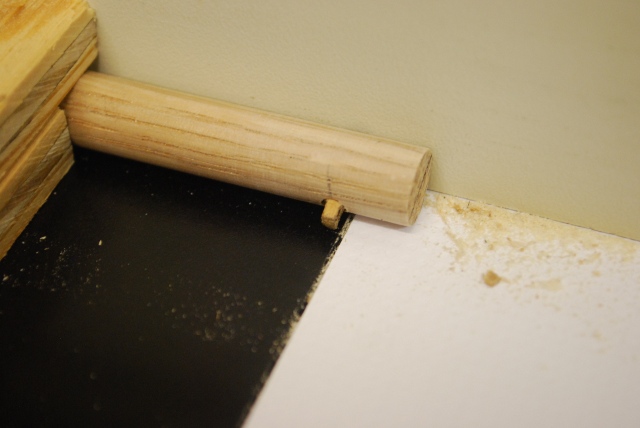
| The slot starts about 1-1/2" from this end and goes to 1/4" from the opposite end. You can see the line, on the far end of the pivot rod, which is the center line of the flapper. |
| Flapper being glued into the slot on the pivot rod, you can see the peg hole is about 45° from the flapper. |
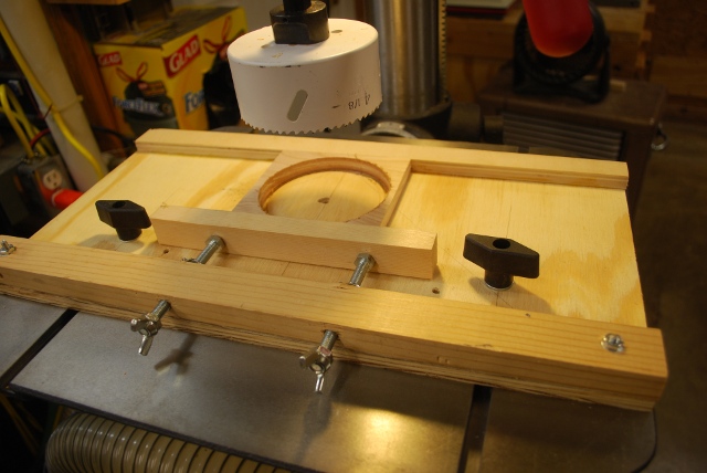
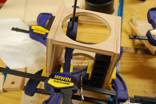
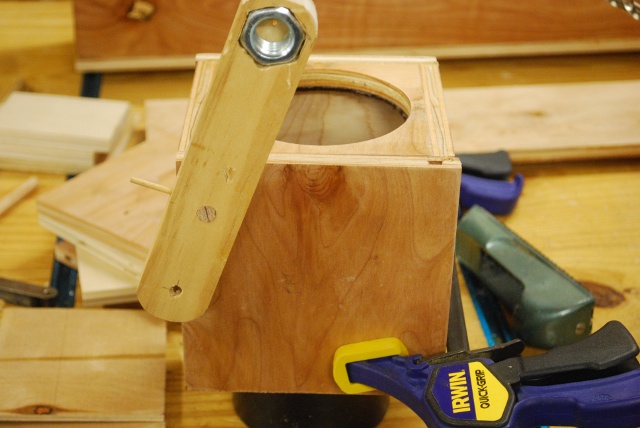
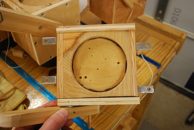
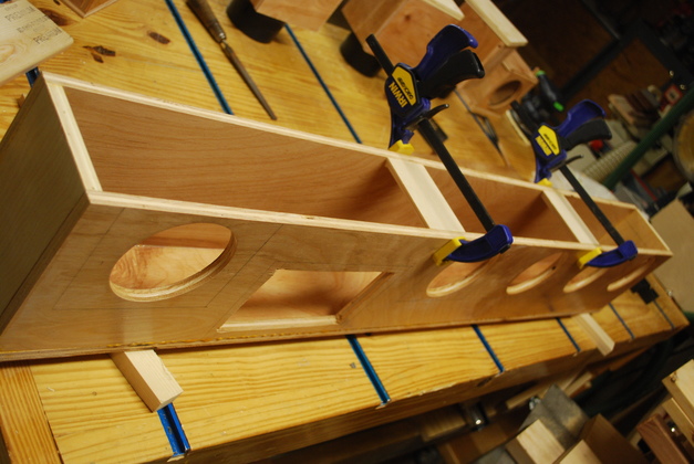
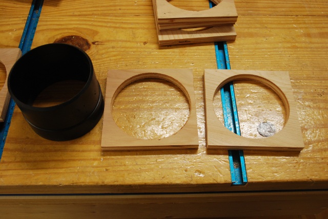
| Hole sawing 4" holes in valve top. When you use a large hole saw you have to clamp the piece very securely. |
| Note the tee nuts and push bar. |
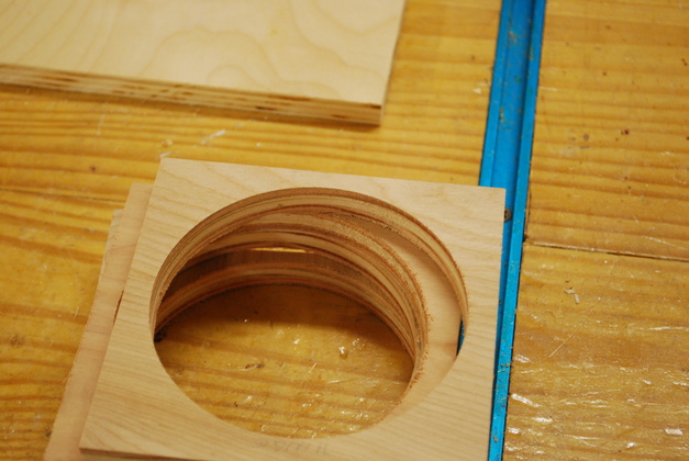
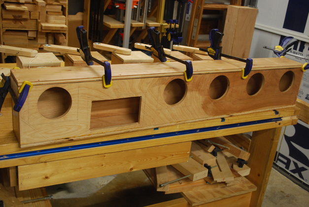
| Stack of valve tops with 4" holes sawed. Hole saws leave rough holes so this took some sanding to get them looking like this. |
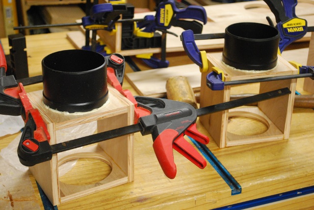
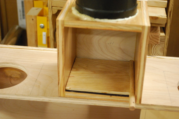
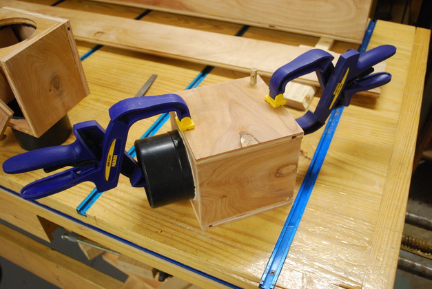
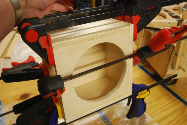
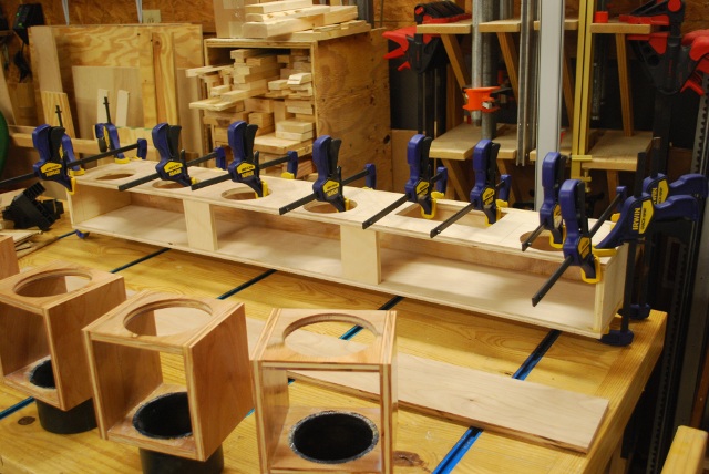
| Valve box being glued up, top and sides, the bottom (on top in pic) is just there as a spacer now. You can see a mini ClampIt to keep things square. |
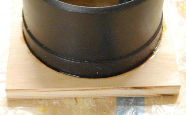
| The Gorilla Glue is starting to foam. |
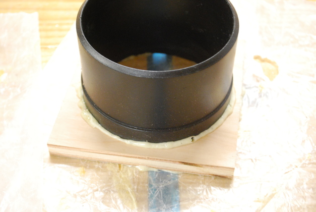
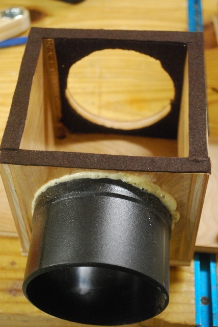
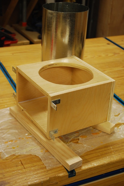
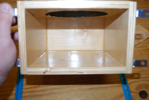
| Bottom being glued into valve box after the 4" nipple is Gorilla Glued, you can see the foam at the base of the nipples. |
| Valve boxes being painted. You'll note the top of the nipple is flush with the inside of the bottom so the valve will clear and there is minimum turbulence. |
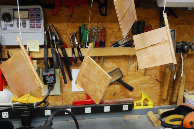
| Flappers being painted. |
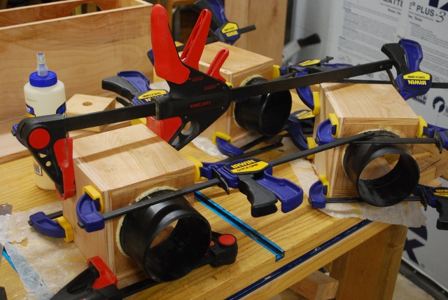
| Backs being glued on valve boxes. |
|
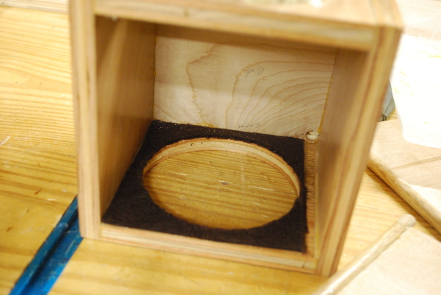
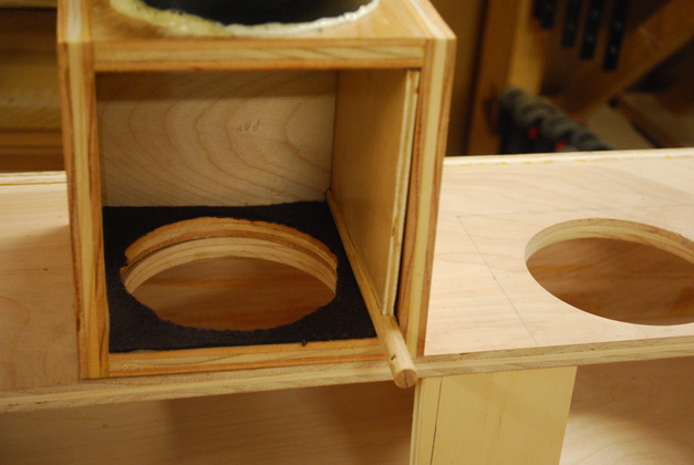
Back glued on and valve gasket/seat in place.
The bare slot on the right side is for the pivot bar, also note the blind hole at the back end for the pivot bar.
The pivot bar slot is also machined out 1/32" so the flapper will sit flat on the felt gasket.
|
| Valve box on top of plenum with valve flapper closed. A slot is machined 1/32" for the pivot bar so the flapper will lie flat on the 1/16" gasket. The distance from the surface of the flapper to the top of the pivot bar is 3/32", see valve detail at the bottom of diagram, the gasket is 1/16" so the slot is 1/32" deep. |
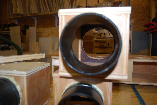
| Valve box on top of plenum with flapper open. The valve box is built to pretty tight tolerances since I don't want the cross sectional area to be much larger than the 4" hose feeding it. You can see here the open valve flapper reduces the CA (Cross Sectional Area) to about 21.56in². The wind flowing, top to bottom in the pic, will help hold the valve open. |
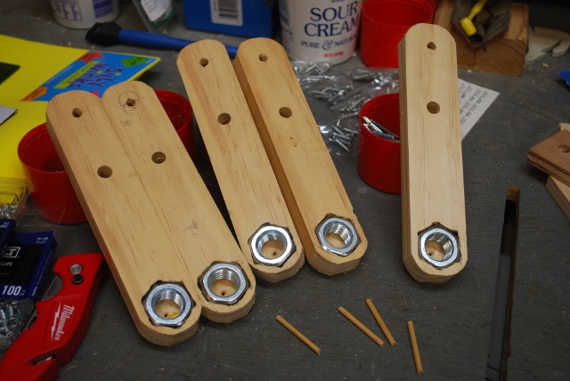
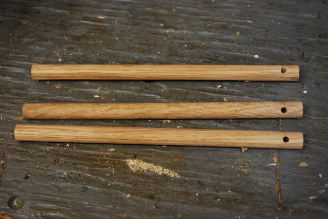
| Valve control bars, here I'm letting the drop of glue holding the nut set. You can see the imbedded nut, the 3/8" pivot bar hole, and the toggle string hole at the top. The pivot hole is 4" from the center of the weight and 2" from the pivot string hole. For the weights (Nuts) I bored a blind hole the diameter of the flats on the nut, then "notched" out for each of the six points, so the nut is "press fit" into the control bar, thats why it doesn't take much glue to hold them. |
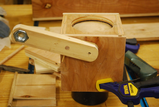
| Valve control bar in closed position. I got the angle a little off the keeper hole in the pivot rod, I'll redrill it to 45°. |
| Valve control bar in open position. The nut weights 1.8 oz. the flapper weighs 1.4oz., the vacuum will help hold the flapper closed, and wind will help hold it open, along with the weight of the nut, but it should be about 45°. The 45° angle means there will be about 1.2oz. of pressure on the flapper holding it open and closed (the vacuum also helps hold it closed). |
|
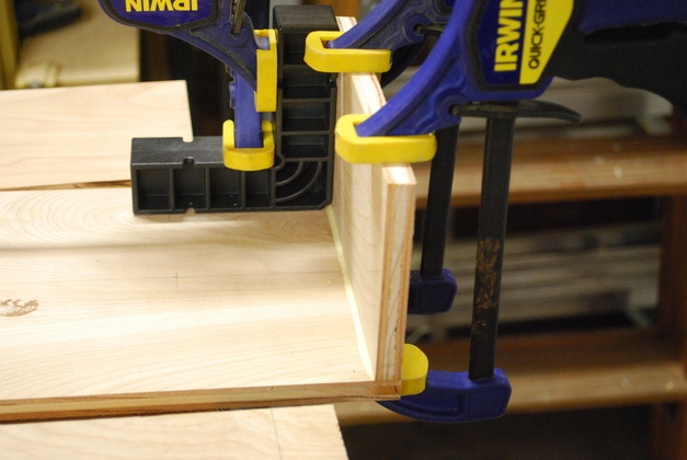
Front clamped ready to drill the screw holes.
I used 1" flat head #8 hex screws (countersunk) to hold the front of the valve box on and the front of the plenum.
|
| Looking up through the open valve, you can see the flapper on the left side, well clear of the wind and dust chips. The wind flow will help hold the valve open, with about 1.27oz. of the weight (in the control arm) pushing it open. |
| A look at the felt gasket under the front cover. This is 1/16" thick sticky back felt, I got it at Hobby Lobby, all the gaskets are made from the same stuff. |
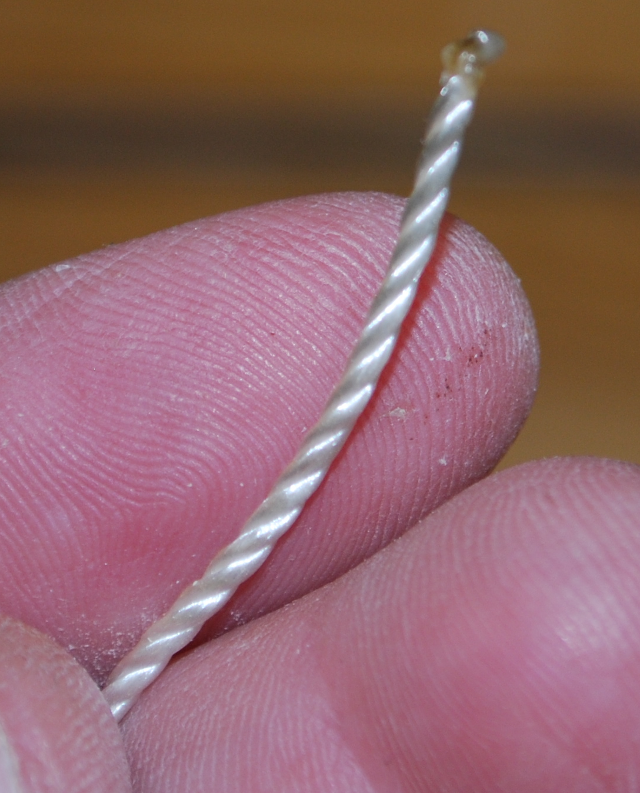
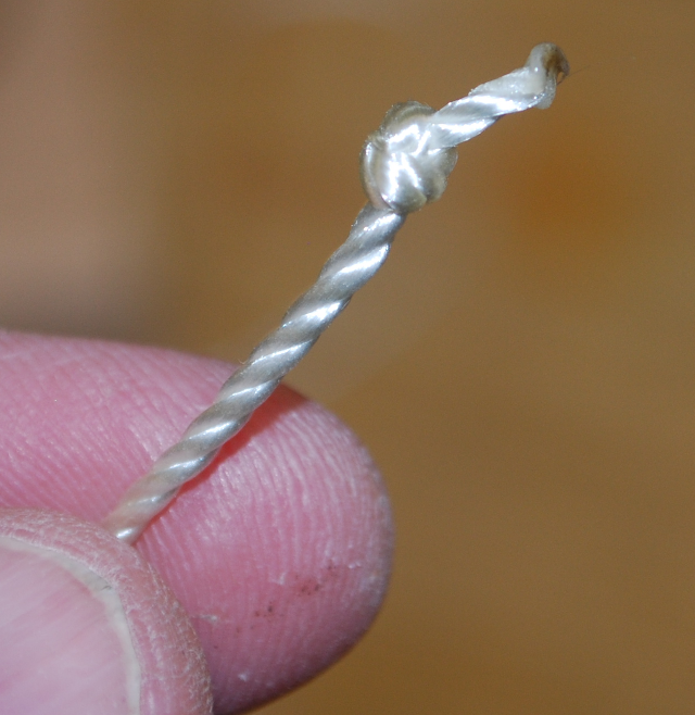
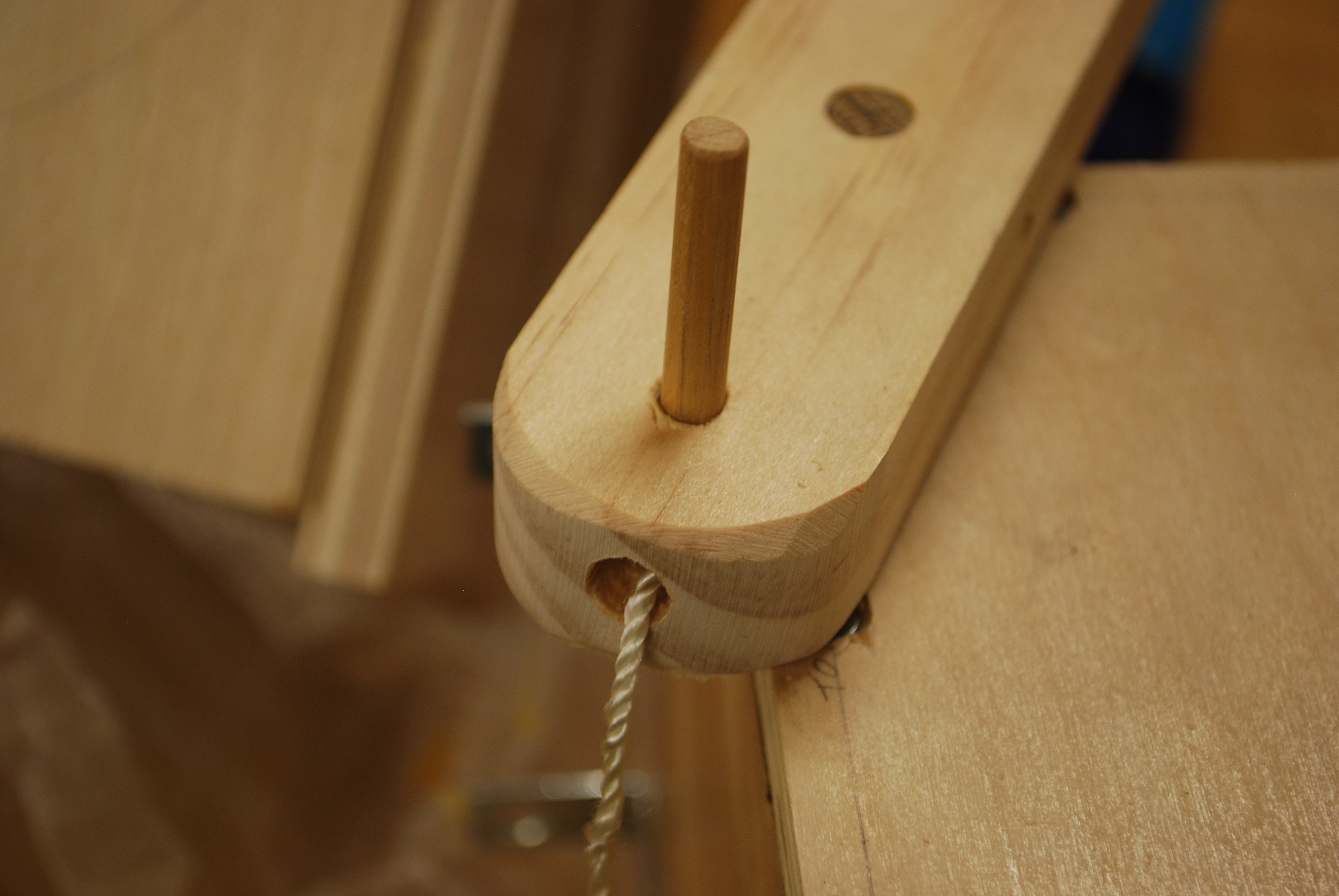
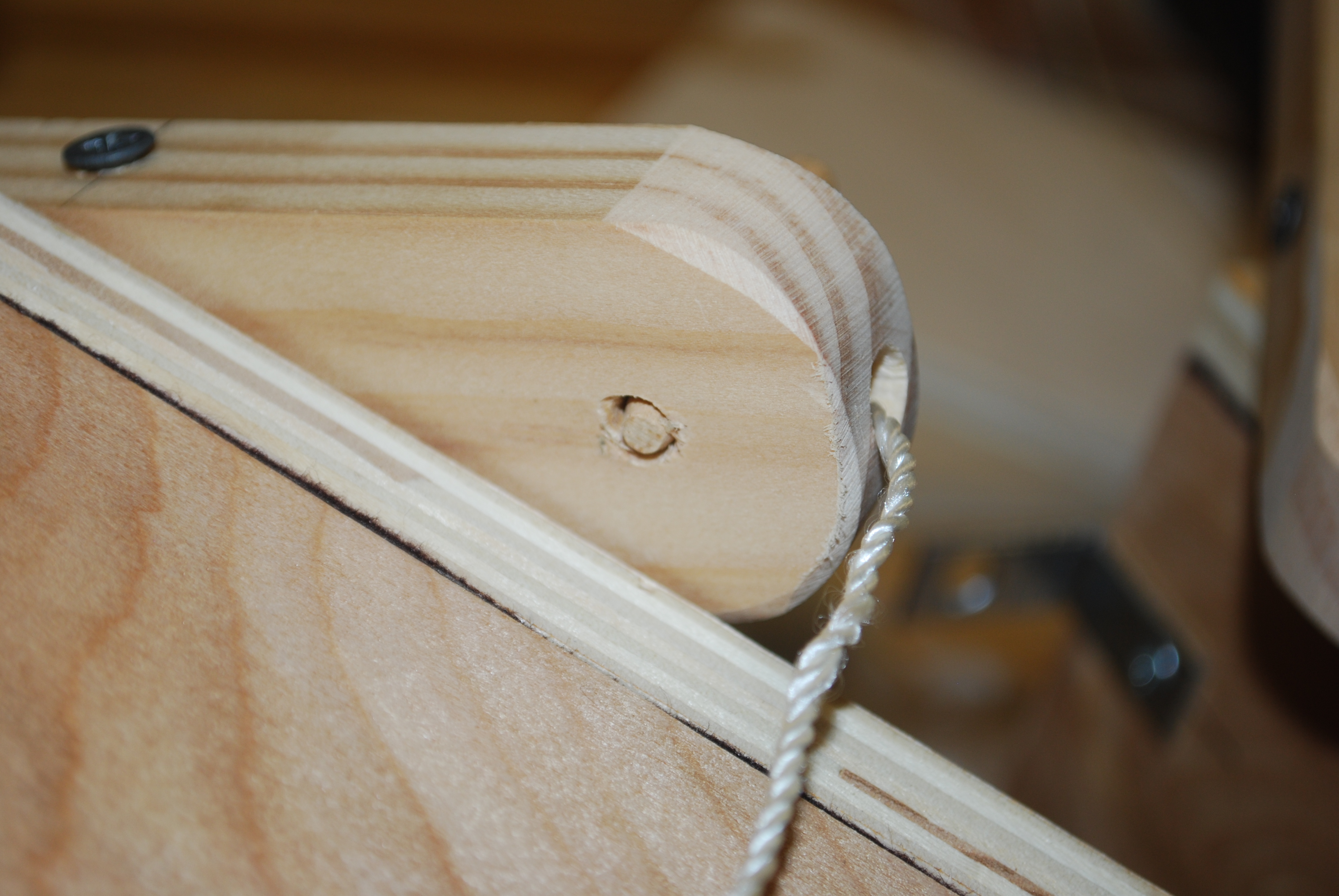
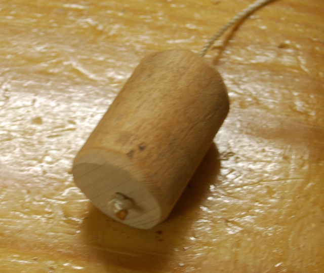
| This peg will be used to hold the toggle string. 1/4" dowel with notch, 3/8" from end, chamfered with a pencil sharpener. |
| The chamfer helps penetrate the string's loop inside the control bar. |
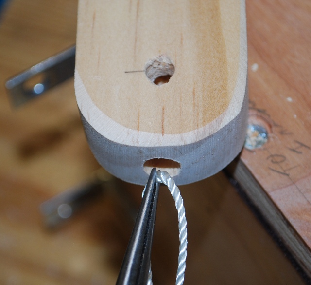
To capture the toggle string, I bored a 1/4" hole through the lower end of the control bar then bored a 5/16" hole from the end to intersect it.
| 
| 
| 
| 
|
| 
| 
| 
| 
|
|
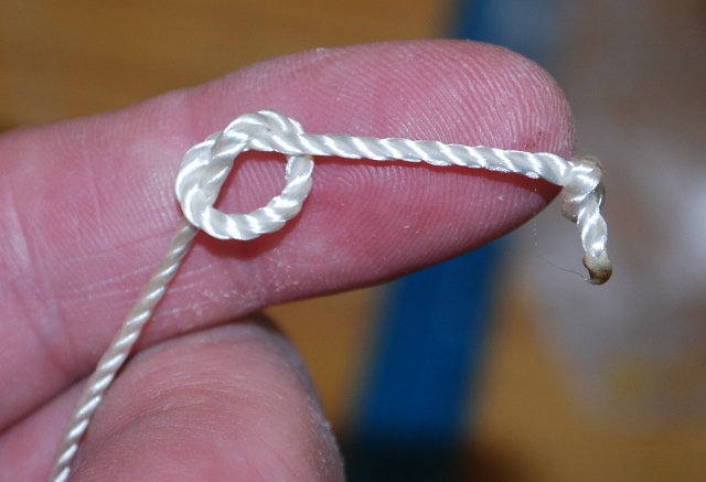
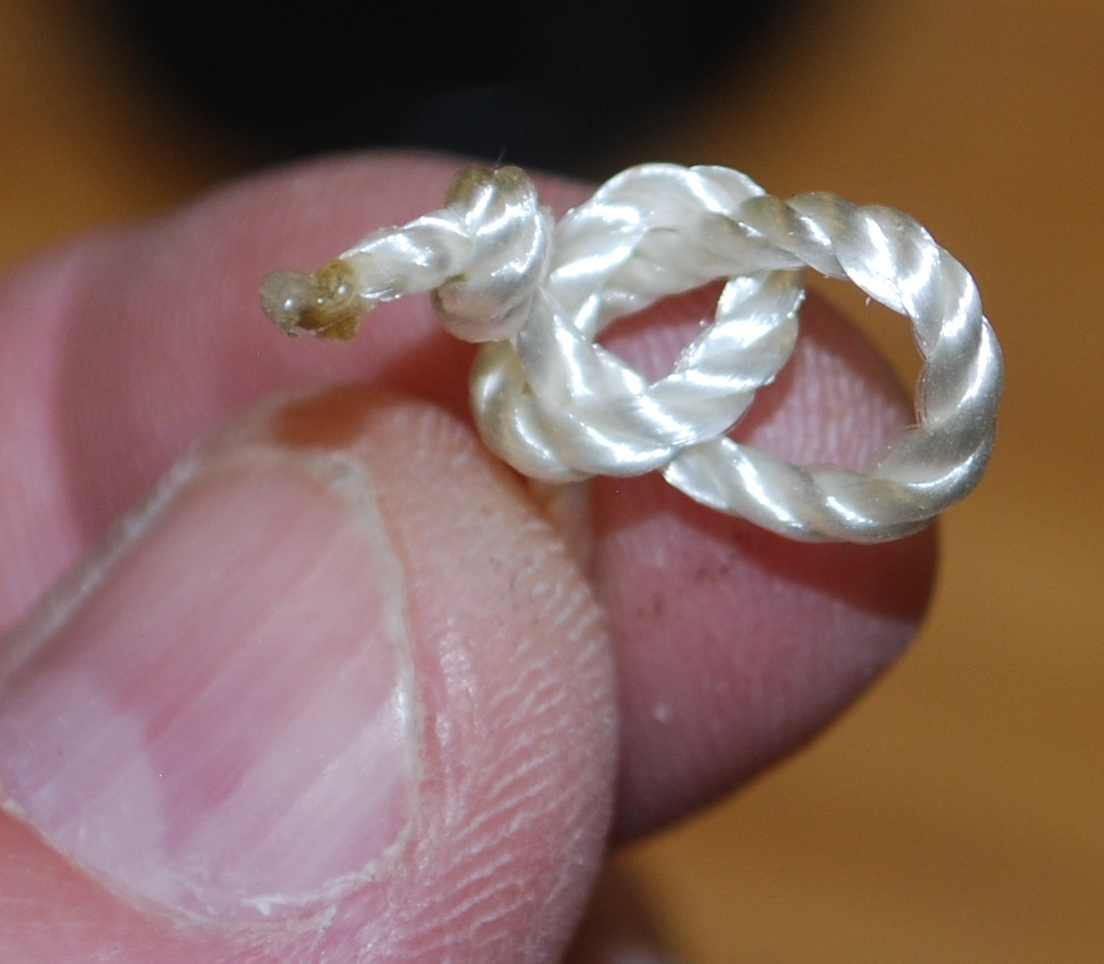
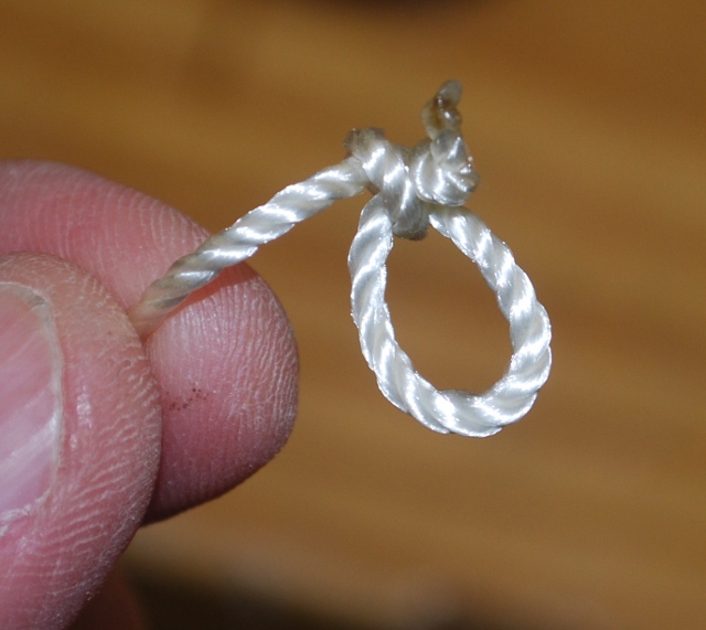
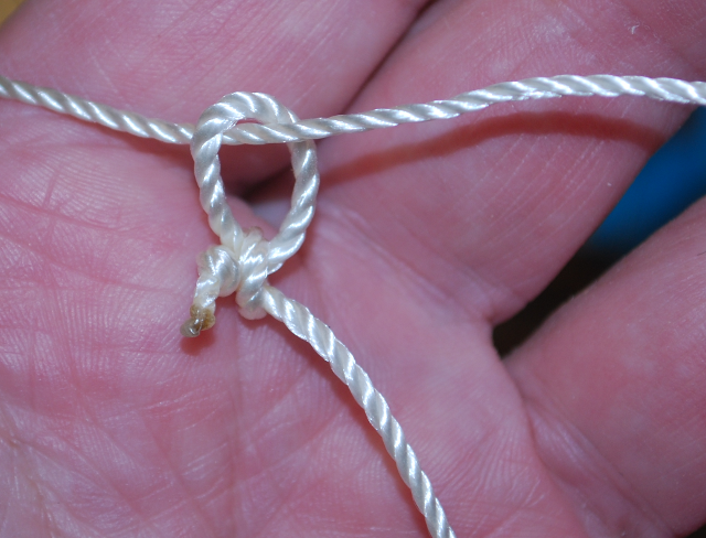
Tie a simple slip knot, then insert the loop from the end, through the 5/16" hole, until you can see it through the 1/4" hole. Then push the dowel through the 1/4" hole until flush on the back side, and pull the loop tight. The 5/16" bore should allow the string to be pulled tight around the 1/4" pin. | ||||
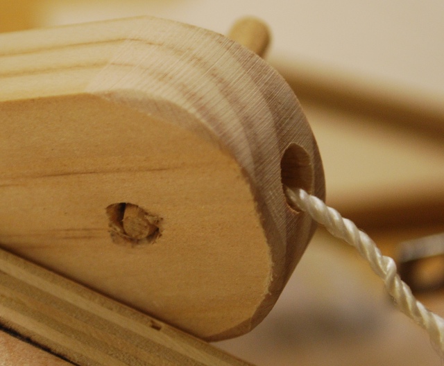
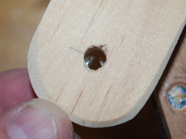
| Back side of control bar with peg holding the toggle string. You can see the 1/4" bore for the pin and the 5/16" bore for the string. |
|
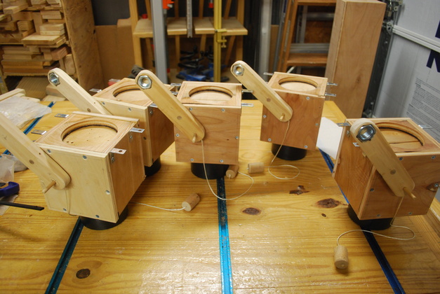
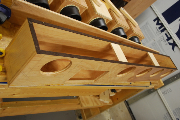
| All 5 valves, with toggle strings, ready to install. Note their mounting brackets on the top. |
| You are looking at the top of the valve box. The mounting brackets are staggered so I can mount the valve boxes closer. The gasket for this surface will be stuck to the plenum box. |
| Plenum ends being glued. |
| Inside of plenum being painted. |
| Two front supports being glued in, the back side of each is beveled 45°, and painted to cut down turbulence. |
| Gasket on front edge of plenum. |
| Fitting front cover to the plenum, ready to drill screw holes. The clamps keep it squarely in place while I drill the screw holes. |
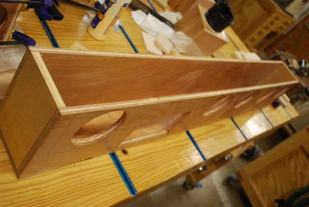
| Riser box being glued. |
| Riser test fit on plenum. |
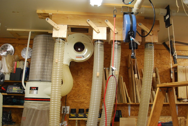
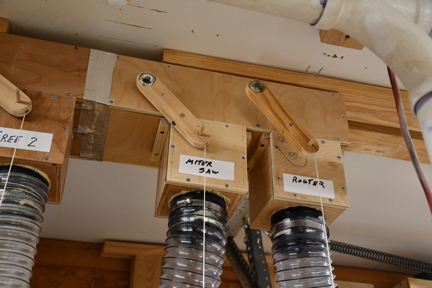
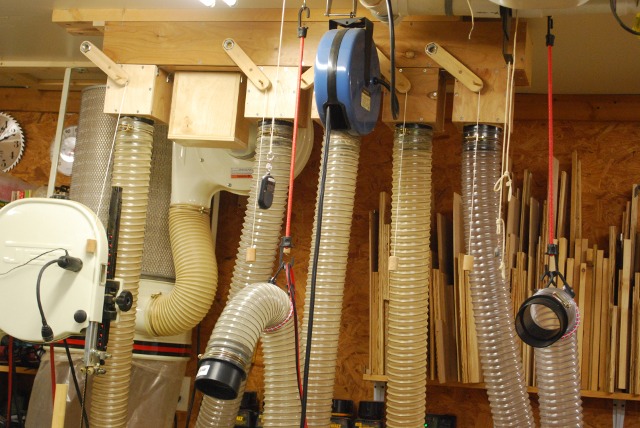
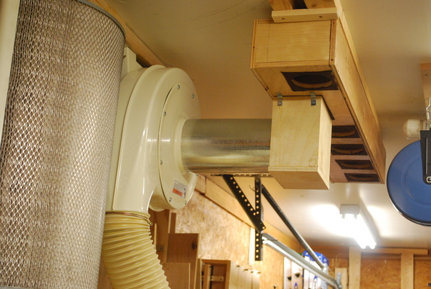
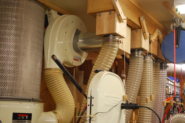
| Valves and hoses installed. You can see how the valve control bars are in front of the plenum. |
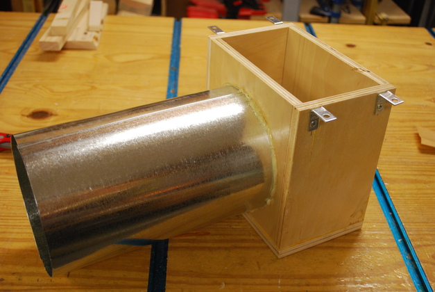
| 6" pipe being glued to riser. If you look closely, you can see the Gorilla Glue foam at the base of the metal pipe. Perspective makes the pipe look larger at the left end, but it's not. |
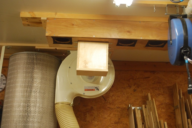
| Install complete. |
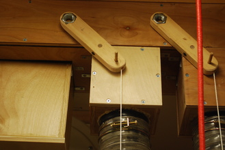
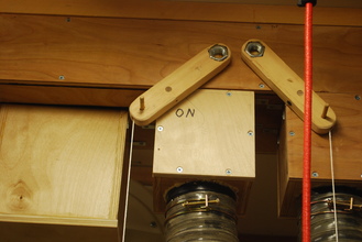
Determine which ones are on!
| 
|
| OFF | ON |