| 
| 
| |
|
4" Plenum Extension
| |||
|
|
|
| |
|
4" Plenum Extension
| |||
| Dust Collection Page | 4" Plenum Page | Ceiling Before Ext | Gaskets |
| Brackets | 4" Plumbing | Diagram | Valve Const |
| Valve Diagram |
When I bought the table saw, I soon realized that it wasn't great at crosscutting long pieces of wood, even with a sled, so I got another miter saw. The table saw was against the West wall, the miter saw, being mobile on it's bench, normally lived in the center of the room and was moved over to the table saw to connect power and vacuum. This soon became a problem since I use both saws a lot. I realized I needed a 4" vacuum connection above the miter saw.
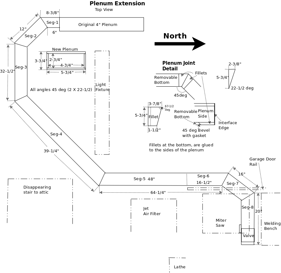
The original 4" plenum carries enough air for two 4" ports (double port) to be open at once (internally 7" X 4"), the extension only needs to support a single 4" port. One 4" hose is 12.57in² the two port plenum 4" x 7" (28in²), a little over twice as large. The single port plenum is 2-3/4 X 4-3/4 = 13.063in², slightly larger that the area of a 4" hose (12.57in²). Back when I worked on engines, I learned you must keep the cross sectional area consistend or you start dropping whatever the airstream is carrying, in this case sawdust.
Remember, from the original 4" plenum, I got the idea from theater organ wind chests, thats why I thought it would be keen to build a plenum from wood.
I needed to extend the 4" plenum but that isn't easy due to other things littering the ceiling in the shop. I did a survey and decided to cut a single exit on the South side of the existing 4" plenum on the ceiling. I must also miter the joints to reduce the drag and impact of particles on the insides of the plenum. This will require 8 segments, joined on the end with gaskets and access "doors" where the plenum is screwed to a brace. Since its difficult to get the segments to perfectly align, I'll tape the joints with metal tape.
When I built the original plenum I screwed the front on allowing me to take it off if something got clogged (hasn't happened in several years of use).
I also needed access to the interior during installation so I could screw the plenum't top to the 2x2s on the ceiling.
The extension plenum will be the same except it is very small vertically so I will need to be able to remove the bottom to install the plenum.
Just like the first plenum, this extension will be painted with polyeurethane, especially the interior, to reduce the resistance to the air moving through it.
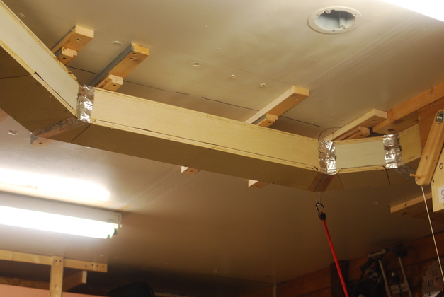
| I have removed the block at the end of the original plenum mounting blocks. |
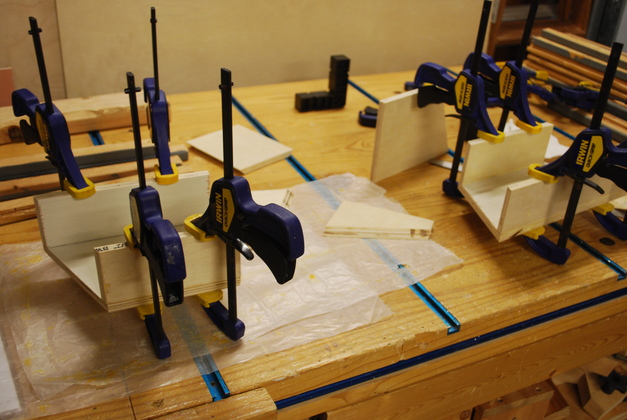
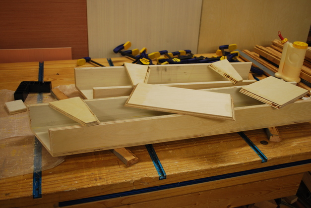
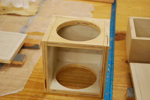
| First plenum segs (segments) being glued. |
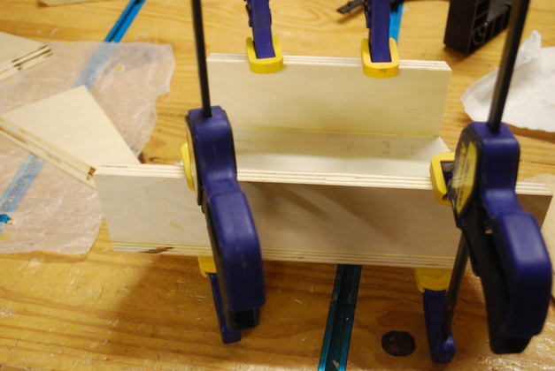
| Closer look at the second ext seg being glued. |
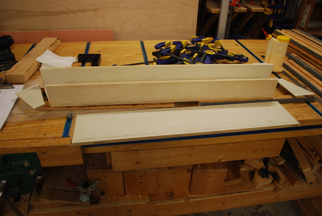
| The 3rd ext seg being glued (1st long seg). |
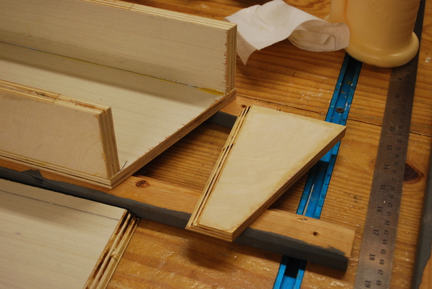
| A fillet ready to glue on. I paint the interior of the segs with several coats of poly before I glue on the lid or fillets. The lid and fillets are also painted till they are nice and shiny on the inside. BTW fillets are usually used to round out corners, but here I didn't want doors that also supported end gaskets, so I use "fillets" to fill in next to miters. If somebody has a better idea of what to call them, please let me know. |
|
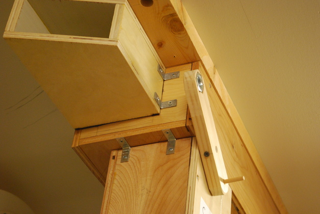
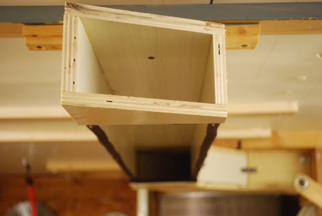
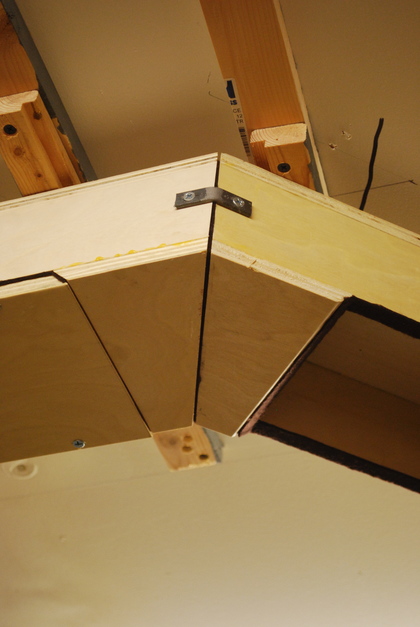
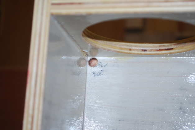
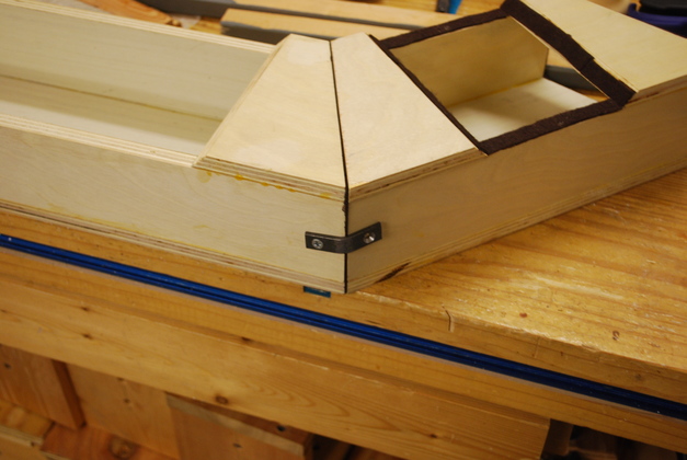
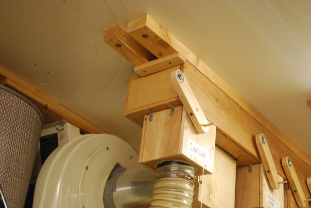
The first seg attached to the end of the orig plenum, I haven't cut the hole into the old plenum yet, not until the extension is complete and sealed.
You can just barely see the gasket at the far end of the seg, against the end of the original, larger, plenum.
This pic also gives you an idea of the difference in size of the two plenums.
Note I used two store-bought 90° brackets and straight brackets on the back.
|
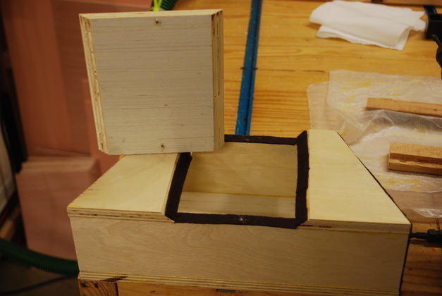
| Plenum door ready to install on top of gasket in beveled hole on bottom of plenum. |
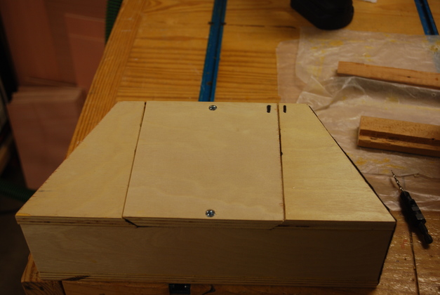
| Plenum door installed. Note the two 1's in the upper right corner of the door, helps me keep them straight if I need to remove several. |
| Second seg installed onto the first. Also note the support blocks screwecd to the ceiling |
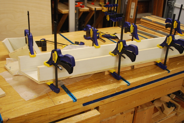
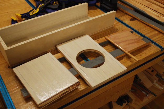
| A long seg being glued. Next, I'll paint inside the glue on the fillets. Some of the longer segs will have two small doors, one over each mounting support. |
| End of a long seg (number 3). |
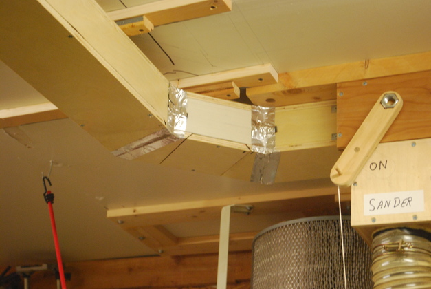
| And around the corner toward the ceiling air filter. Note the 1x2 holding up the seg while I make sure the gasket is tight against the last piece (on the left). |
| One of my corner outside brackets. |
| Looking toward the North, you can see the support blocks screwed to the ceiling joists as the ext will go North. |
| Next seg mounted, this one has a flat end (not mitered). One more to the corner. |
| Last two main segs about to be glued. |
| Last two segs in place. |
|
| I taped all the joints with metal AC tape. Even though I used gaskets, its really tough getting the segments to butt up firm enough to make a great seal, so I cheated, just a little. With the house expanding and contracting summer to winter, I thought this was a good idea. |
|
| Metal AC tape on last two segs. |
| AC tape on first two segs. I had already sawed the hole in the original plenum to connect the new extension. |
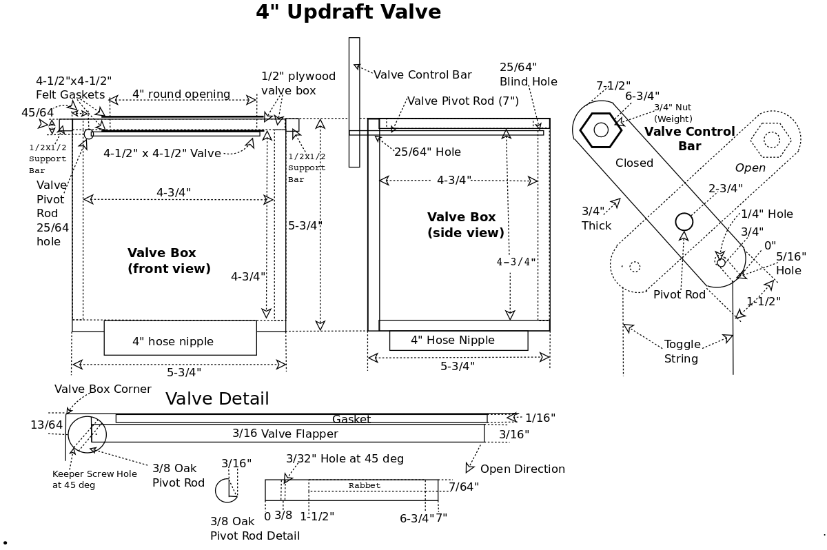
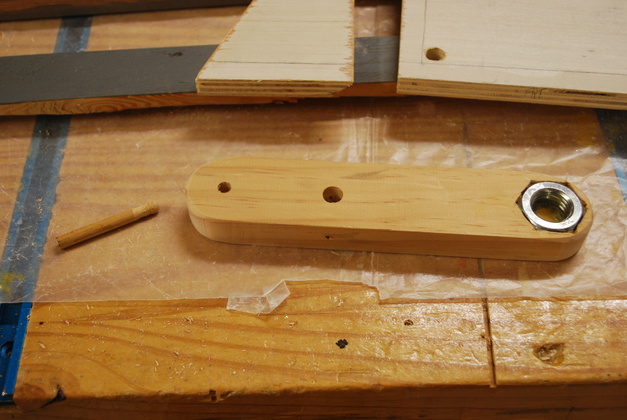
This valve will be exactly like the other 5 on the original plenum: 1/2" birch plywood walls with a 3/16" thick, 4-1/2" X 4-1/2" flapper on a 3/8" diameter pivot rod with same control bar etc.
The trickiest part of this used to be machining the groove along the side of the pivot rod for the flapper to be glued to.
But, I found a good way to make this work, I machine a flat on the pivot rod, lay it on a flat surface, lay the flapper on something 1/16" thick, then glue the flapper to the rod.
You might even put a business card under the pivot rod to raise it about .008" above the flat, this will give just a little clearance for the rod to turn without rubbing on the top of the valve box.
| Vavle base with the flapper being painted. |
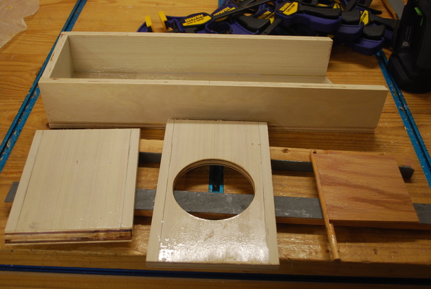
| Valve housing glued with bottom and top holes cut. |
| Blind hole for end of flapper pivot rod in back of valve housing. Note shiny interior, polyeurethane makes the dust fly by, less turbulence. |
| Valve front corver on right, control bar on left. |
| Valve base with flapper paint drying. |
| End of the extension, this is where the valve will be mounted. |
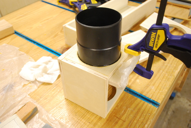
| Valve with 4" nipple being glued in. |
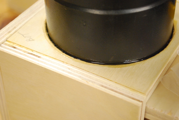
| Closer look at Gorilla Glue just after application. |
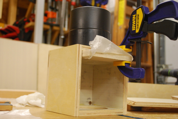
| I had to clamp a flat piece of plywood covered with waxed paper to make sure the bottom (in pic) of the nipple was flush with the inside of the valve housing. |
| Valve control bar with toggle string keeper. |
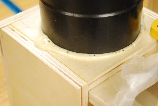
| Gorilla Glue foaming up, it fills the voids, makes this an air tight joint. |
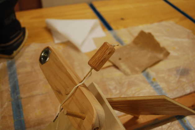
| Control Bar's toggle string weight being painted. I put a 1/16" drill bit in the keeper retainer hole to hold the dangle weight while it dried. |
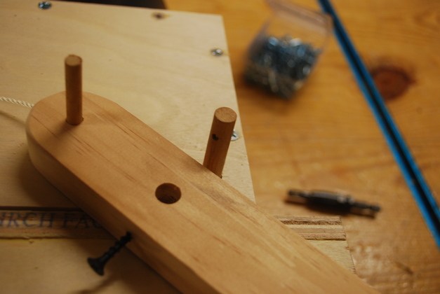
| Screw started in the control bar's keeper hole. |
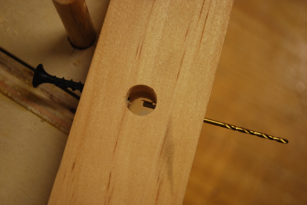
| I ran the little drill bit in from the other side as a feeler, then pulled it back, inserted the valve pivot rod and gently rotated while pushing the drill bit until I felt the bit go into the hole in the pivot rod. Then I knew the hole was lined up on the other side so I removed the little bit and drove the keeper screw into the pivot rod on the other side. |
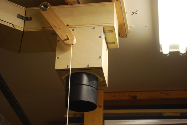
| New valve hanging from the end of the plenum extension. |
| Look at the new valve from a little farther away. |
| Another look from the other side. |
| New 4" hose hanging from new valve. |
|
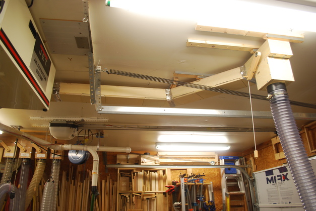
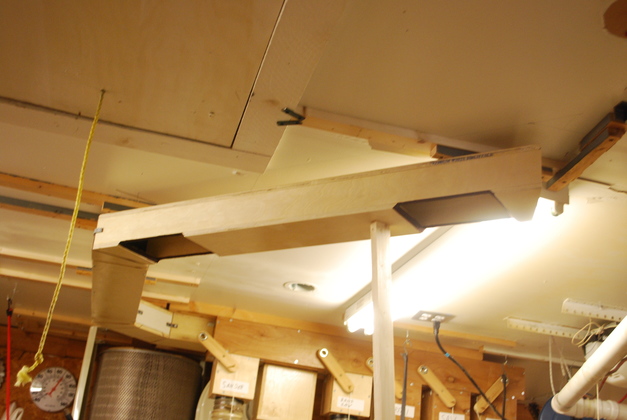
| Look from a different direction. You can see the last few segs of the plenum extension. |
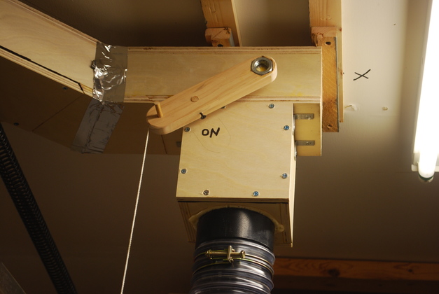
| I added the ON notation under the control bar. |
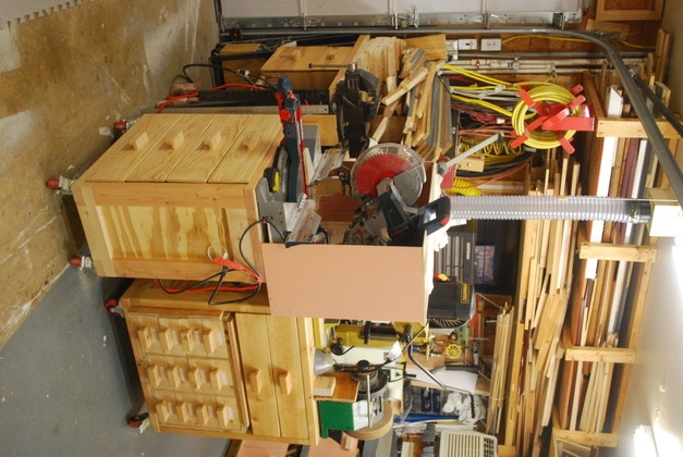
| Miter saw in it's normal place, now with 4" DC line and it works. |
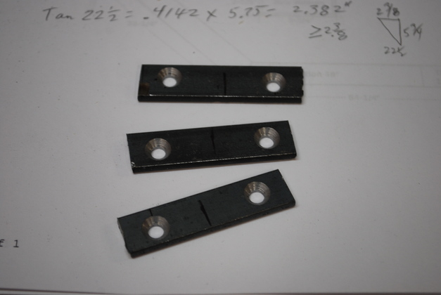
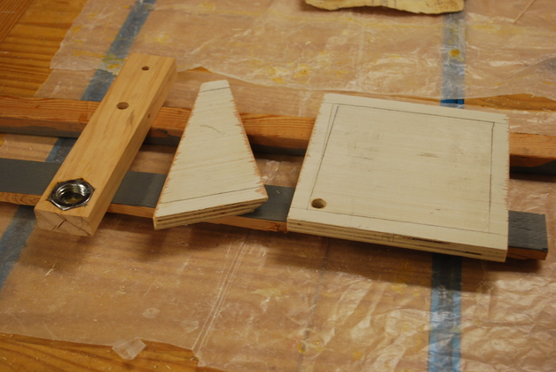
| Home made brackets from 1/2" wide flat bar stock, 2" long with a hole drilled and counter sunk 3/8" form each end. I needed some way to help keep the plenum sections aligned when installing so I came up with these. Oops, excuse the trig, I was figuring how to make the fillets. |
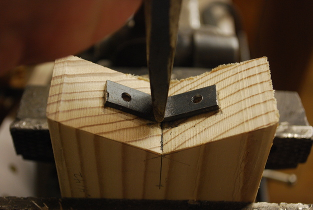
| I cut a 45° notch in the end of a 2x4 then used a cold chisel to bend the bracket. Some with the counter sinks inside and some with them outside the bend. I bought 72" of 1/2" wide flat bar stock, cut it into two" lengths, then drilled and countersunk a hole in each end for mounting screws. |
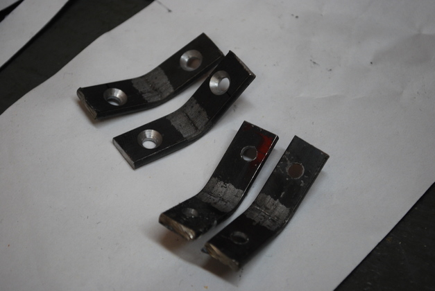
| Two pair of brackets, both inside and outside. |
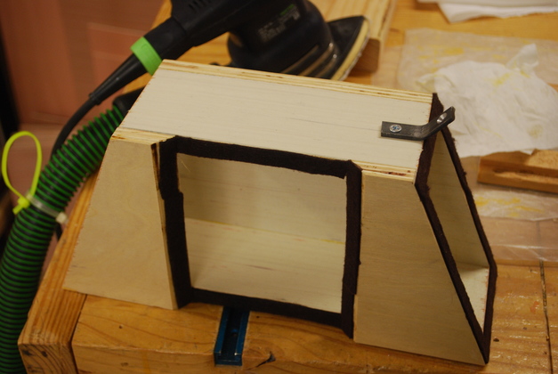
| One of the 45° inside brackets mounted on the end of a plenum seg. Note the gasket material here. |
| Heres one of the outside bracket installed. |
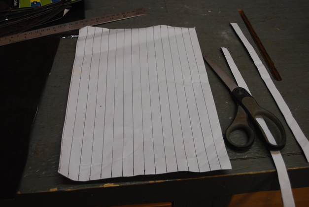
| I made lines every 1/2" on back of the peeley backed 1/16" thick gasket material from Hobby Lobby. |
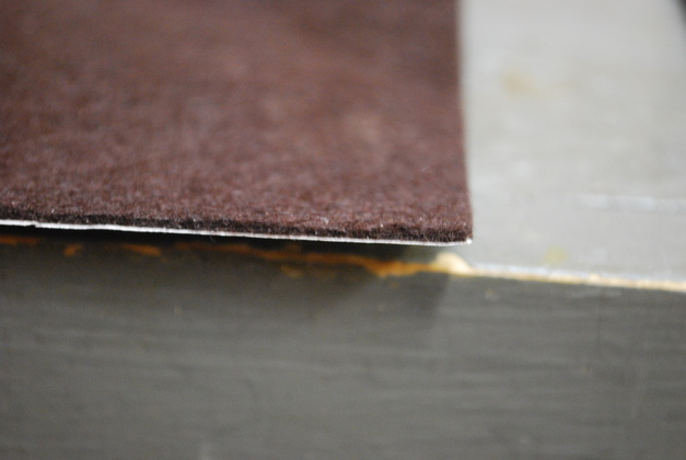
| Close up of the edge of the gasket material. Its 1/16" felt with sticky back from Hobby Lobby. |
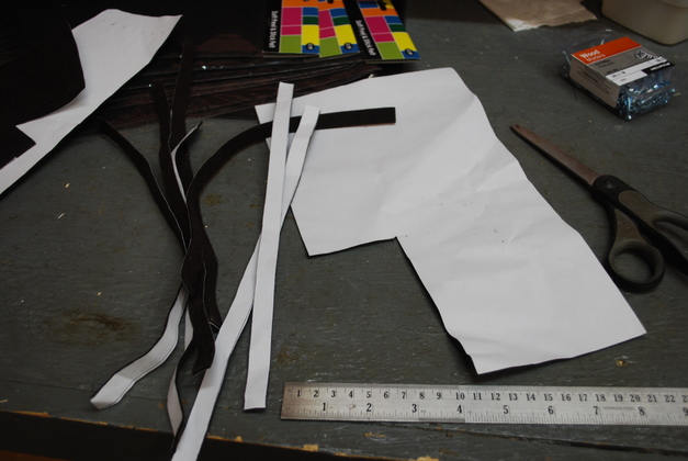
| 1/2" gasket strips cut ready to apply to 1/2" plywood edges. |
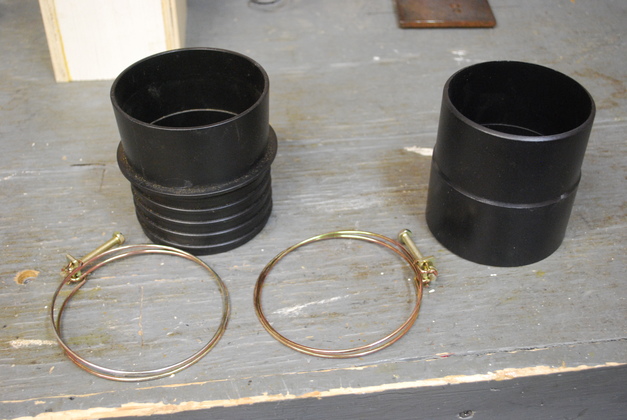
| 4" hose end, nipple, and clamps for the new valve's down hose. |
| South end of the original 4" plenum, this is where the extension will start. |
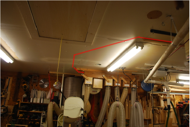
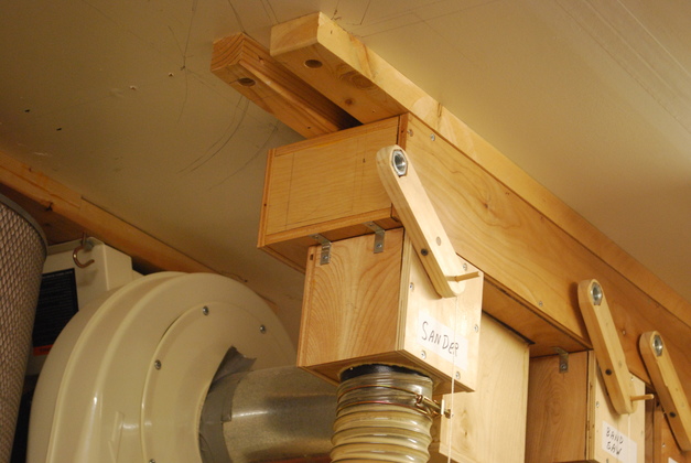
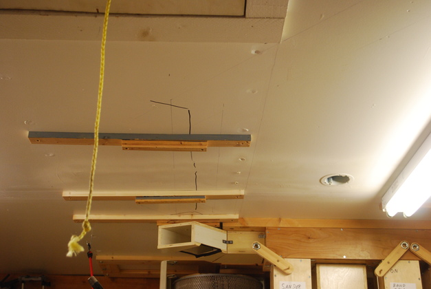
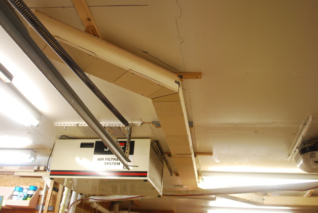
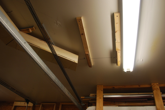
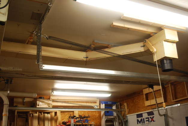
| Looking West at the ceiling toward the original 4" plenum, on the far side. You can see the disappearing stair in the left foreground. The extension will come out of the orig plenum's left end turning toward us, run toward the disappearing stair, then miter right between the disappearing stair and this end of the light fixture and miter right, again, toward the front of the garage (North). |
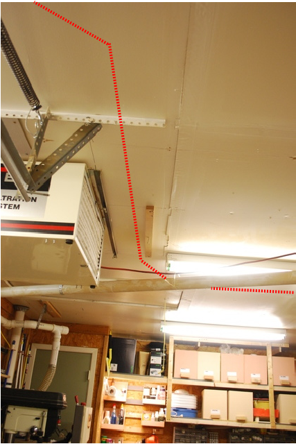
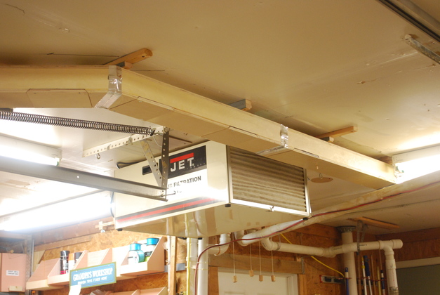
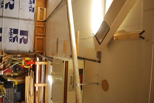
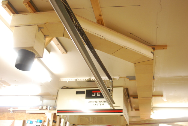
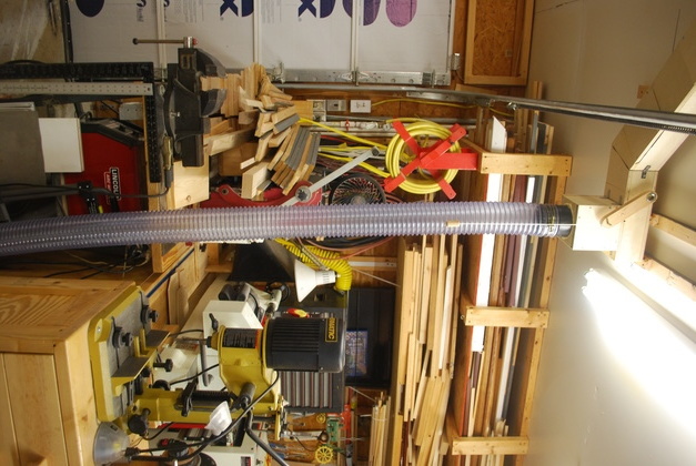
| Looking South, the new plenum will come just to the right of the Jet dust filter to right above our head. The diagonal brace for the garage door rail support will be flopped to the other side of the support, and the wooden bar will be removed to clear a path for the new plenum extension. |
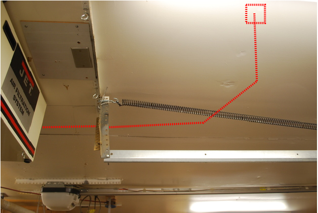
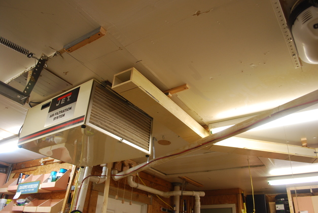
| Looking West at the ceiling over the miter saw. The extension will come from the left behind the Jet filter, past and on the far side of the garage door support then turn toward us (East) to this side of the garage door rail where the new valve will be. |