| Current Sensor Test | |||
| Back To Automation |
I decided to make a test setup for the current sensors so I didn't have to test while connected to high voltage.
Years ago I bought a XR2206 Function Generator from Amazon.
This little $8 gadget can put out a sine, square, or triangle wave with a frequency of 1HZ to 1MHZ.
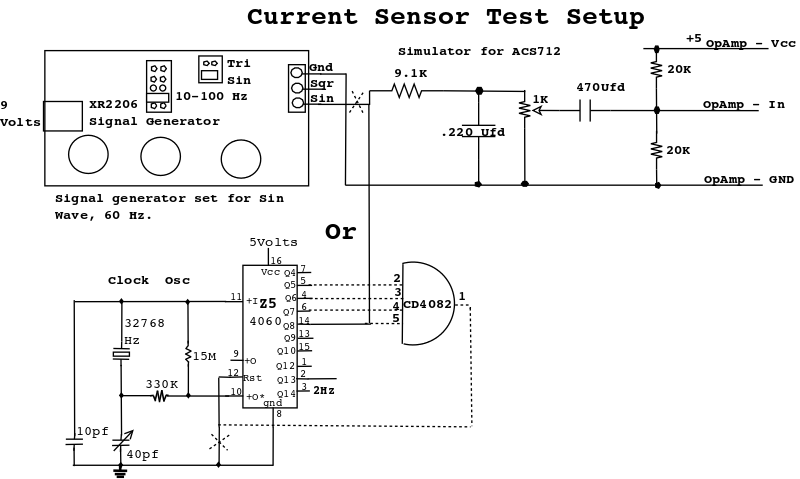
The input circuit smoothes it out the sine wave and has a variable attenuation to control the amplitude of the sine wave going to the opamp board.
The circuit also adds the 2.5Volt offset like the ACS712's output.
Crank the pot to simulate various currents being sensed by the ACS712.
In case you don't have a function generator, I noted an optional circuit as the signal source, using a CD4060B and a crystal. The crystal (32768Hz) is readily available, they're used in quartz clocks/watches. The 40Pf variable cap should actually be set to 39Pf. This will produce a 64Hz signal, close enough to 60Hz for the opamp board. You could add a 4 input and gate (CD4082) and get it dead on to 60Hz, by truncating the 4060's counter at 60 (0X3C).
XR2206 output impedance: 600ω

|
|