| 
| 
|
|
|
Current Sensor (Isnsr)
| |||
|
|
|
|
|
|
Current Sensor (Isnsr)
| |||
| Test Circuit | Sensor build | 240 Volt Current Sensor | CT Snsr |
I have replaced this current sensor with a new design using a CT (Current Transformer)
Please check out the new CTsnsr.
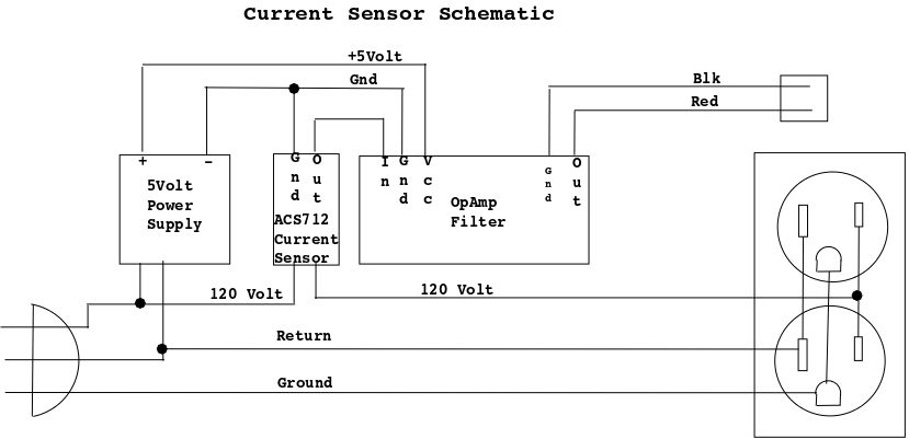
The other dust collection automation systems I have seen use an ACS712, Hall Effect device as the current sensor, and so will I.
The better ones use the 20Amp version to minimize the drop across the sensor.
The ACS712 20A has a small delta output (100Mv/amp PtP) and about 2.5V offset,
I will be running these sensor outputs several feet in a potentially noisy (electrical) environment, so I am going to AC couple (get rid of the 2v offset), filter, and amplify the signal.
The ACS712 sensor signal output is a 60Hz sinewave at 100 MV/amp PtP, that isn't much in a noisy environment.
Since I have ample 120V AC available in the Isnsr, I am using a tiny 120V AC to 5V DC DiyMore power module to power the ACS712 and amp so I only need the amplified signal and ground wires back to the Dust Auto system.
bTW, I read some feedback on these DiyMore power supplies and one guy had a signifigant DOA rate, I tested all of the ones I have and all worked great.
If you don't want to add the 5 volt power supply, you can run a third wire to each sensor for the 5 volt vcc.
This has the effect of not running the ACS712 and filter all the time.
My dust automation system is powered from the light circuit in the shop, so its only on when I'm in the shop working.
Most of these systems perform successive reads across 1/2 - 1 second detecting maximum and minimum peaks to find PtP voltage, then calculate and scale to volts, then calculate (PtP/2 * .707) to get RMS volts. This is unessary, since average voltage value is not required just the digital value. Plus this makes it hard to read 8 sensors in a timely fashion (while reading the Nano isn't responding to the keyboard). The voltage from the sensor doesn't have to be highly accurate just consistent and enough amplitude to tell on from off current and be able to ignore things like worklights on the same circuit. I originally tried a signal conditioner but was disappointed in the result. I tried an opamp half wave rectifier and have been very pleased. The output of the ACS712 is riding on a 2.5V level this is ideal for an opamp circuit. The sensor output is about 200 - 300 Mv off and 2.8 - 3 Volts when a motor is running. I now have 6 current senors working, the 240 volt for the tablesaw tested OK at 120 Volts, now I'll get 240 Volt, 15 Amp connectors and test it at higher voltage. The DiyMore 5 volt power supply says it works at 265 AC volts which is a little close for comfort in my opinion. The ACS712 has a 2.1KVAC breakdown (hipot). I sampled for 20MS in the control program and can poll all 8 sensors in about 180MS. This makes the Arduino control program much more effecient since I won't have to wait many MS while I record mins and maxs then calculate RMS volts.
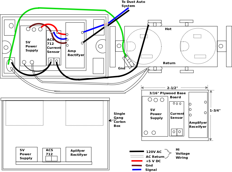
I decided to try a new work (Nail-In) single gang receptical box which has plenty of room. These new work boxes do not have cable clamps so I'll use a tie wrap to restrict cable movement. Since I'm adding an opamp filter to the ACS712, I'll use a small piece of thin plywood (2-1/2" X 1-3/4") and glue the modules to it using silicone sealer.
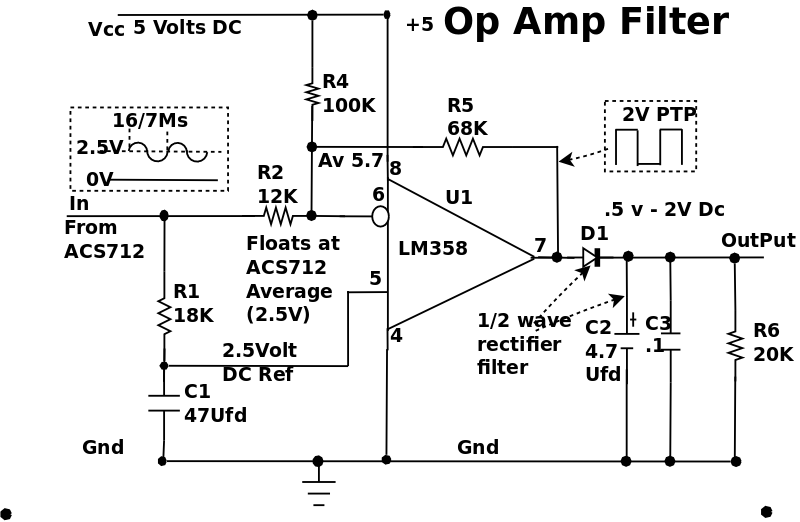
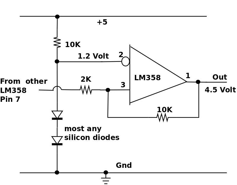
Circuit Description see skiz below.
The opamp is rail to rail will operate, and switch between 0 and +5 volts.
The resistor R1 and capacitor C1 filter out the 60Hz ripple from the ACS712 leaving only the offset voltage (2.5 volt) as a reference voltage for the non-inverting input of the opamp.
When there is current flow through the ACS712, a semi-sinusoidal waveform passes througn R2 to the inverting input (pint6) of the opamp.
The output of the opamp (pin7) is routed back through R5 to the inverting input (pin 6).
The ratio of the two resistors R5 / R2 determine the overall gain of the circuit, about 5.6, which will cause the opamp's outout to have a large swing (rail to rail).
The output of the opamp (pin7) is half wave rectified by D1 and filtered by cap C2, C3, and resistor R6.
The reason for two caps is the large electrolytic (4.7Ufd) filters out low frequency ripple (60 Hz) the smaller ceramic cap (.1 Ufd) filters out higher frequencies.
Resistor R6 provides a discharge path for the charge on C2 so when the sinusoid stops the cap will quickly discharge (about 100MS).
The resistor R4 feeds about 12 Ua into the opamp's summing junction (pin6) which forces the output low, until a sinusoid is applied to the input.
Originally I had thought to add another 100K potientometer in series with R4 to allow tweaking the threshold a little, but so far, it hasn't been necessary.
D1 can be almost any silicon diode, I used some tiny glass diodes from my parts box (originally purchased a diode assortment from Micro Center).
The output, when no current through the ACS712 is about .2 volts, and 2.9 volts when there is motor current, making it easy on the nano to detect.
If you need a little lower threshold for a low current device, you can increase R5 (to like 330K).
Reactance of a capacitor:
Xc = 1/(ω C) where ω = (2 π ƒ)
The 240 Volt sensor (tablesaw) will have a single 240 Volt, 15Amp receptical and pig tail plug.
As I said earlier, the Diymore 5volt power supply can operate from 85 - 265 Volts AC (RMS) and thats a little close to the 240 Volt power for me (I've often seen our house voltage at 250V).
If it blows a 5 volt power supply, I'll run the power supply between one phase and ground (120 Volts AC).
Normally this isn't done (its a NoNo) since you should always draw current from phase to phase or from one phase to return, but 240 Volt single phase circuits don't have a return line (power supply draws about 15Ma under load).
The ACS712 has 2.1 KVAC breakdown (hipot).
05/07/20, all sensors insatlled and running, so far 240 volt sensor works OK, entire system works as expected.
I built a small test rig, on a small perf board, to test the opamp/filter. It consists of a sine wave generator, a filter with adjustable ouput, capacitor coupler and two resistors to offset the output just like the ACS712. I also noted an optional oscillator circuit using a CD4060 in case you didn't have a small function generator.
If I ever have problems with the sensors, I'm going to use the second amp in the LM358 as a comparator with hysteresis and see if that'll fix it. This will set the threshold to 1.2 V and eliminate any chatter.
|
|
|
|

|
3/16" thick 2-1/2" X 1-3/4" Isensor component mounting boards cut out. |
|
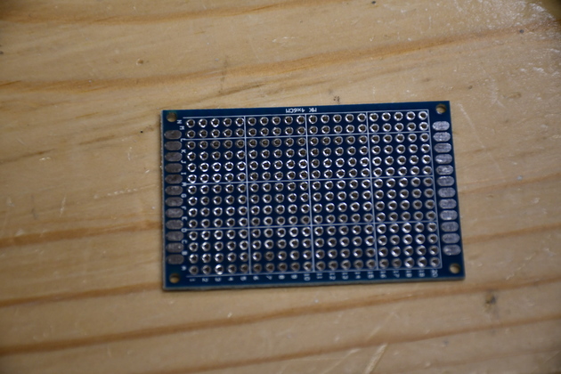
Small Pcb I bought in a pack for making Arduino shields. |
|
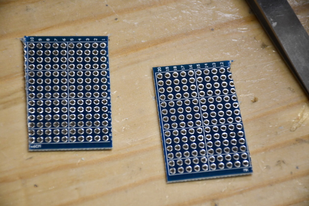
I trimmed off both ends and cut it in half, making 2 pcbs 1" X 1-2/5";. |
|
|
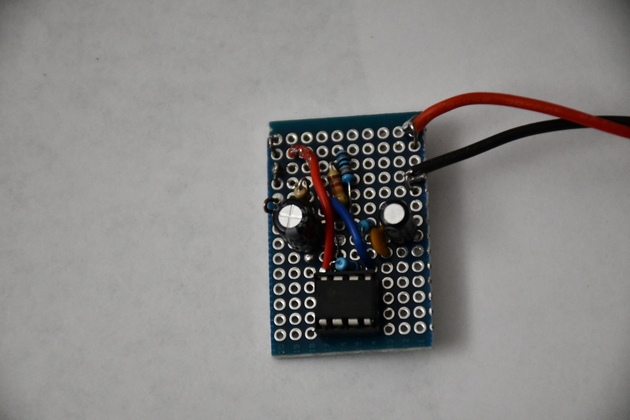
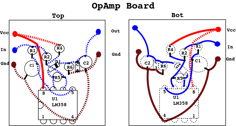
Top of opamp board. The LM358 is at the bottom. Note the red power jumper down to pin-8 of the opamp and the red and black ouput wires on the right. |
|
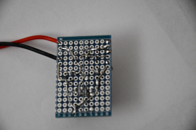
bottom of the opamp board. |

|
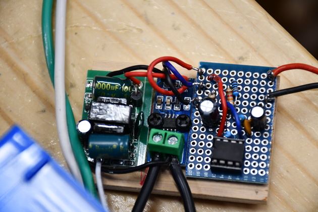
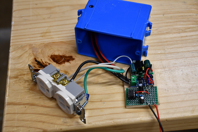
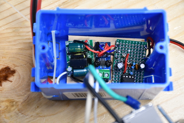
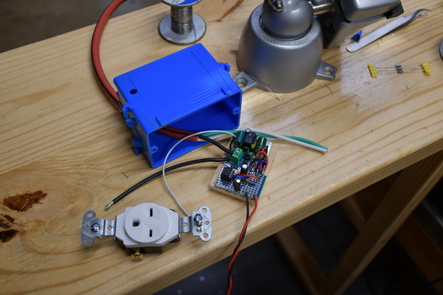
Component board: 5V power supply (left), ACS712 (center), and opAmp board (right). You can see the 5V power supply on the left, ACS712 center, opamp board on the right. |
|
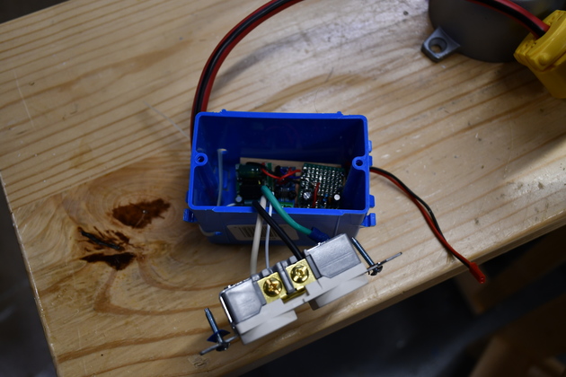
Entire current sensor internals. |
|
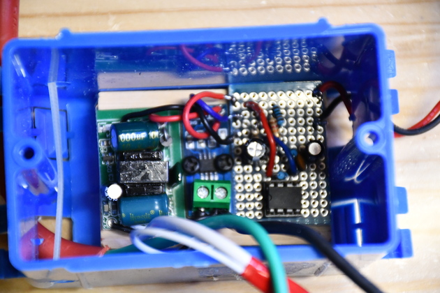
Component board in the bottom of the nail-in box. |
|
Closer look at how the component board fits into the bottom of the nail-in box. Also notice the sensor ouput wires (red and black) on the right. You can also see the spot tie, on the left, passing through two holes and around the left end to restrain the pig tail (AC power cord). |
|
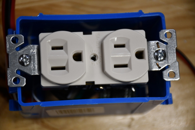
You can just barely see the component board below the dual receptical. |
|
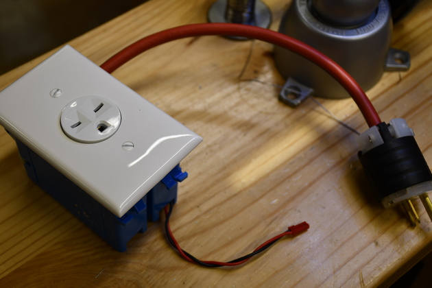
Every thing except the cover plate. Notice the AC pig tail on the left and the sensor output on the right. |
|
|
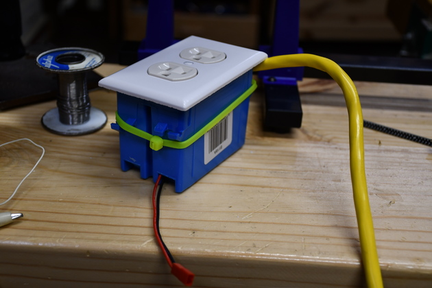
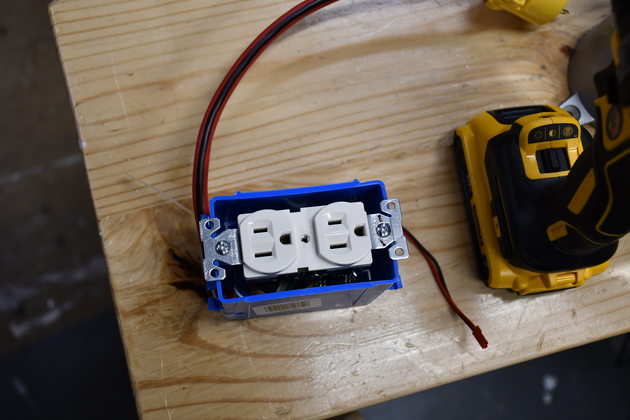
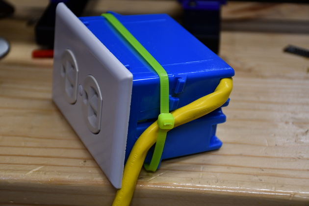
Finished current sensor. Note I used the spot tie because the box doesn't have a clamp on the 14-3 cable. This is actually the prototype, on the subsequent units, I drilled a 1/4" hole from one side to the other and ran a single spot tie through it to restrain the pig tail. |
|
Other end of the box showing how the spot tie keeps the cable from moving the component board inside. |
Well the ACS712 is supposed to be rated at 60Amps and hipot to over 1000 Volts, but...

I was ripping a SYP 2x10 which pinched the blade and stalled the motor.
The power shut down immediately.
I free the blade but the saw wouldn't start, so I checked the breakers, they were in.
I checked both phases, one was 249 Volts the other was 110 Volts, Not good!
I checked bothe phases in the breaker box, and all was well.
I thecked the 250Volt outlet in the ceiling above the saw, both phases good.
I checked both phases on the ouput of the current sensor and one was 110Volts.
I disconnected the 240 Volt sensor and disected it to find the problem.
Turns out the ACS712 was destroyed.

Apparently the current surged when the saw motor stalled (normal) so that has to be what killed it.
I've started designing a new current sensor using a CT (transformer).
| The 240 volt sensor for the table saw, being assembled. The actual sensor circuit is identical to the 120 Volt sensors, just the plugs are different, no return, so the 5v ps is connected directly across both phases of the 240 Volts. I noticed that I have a NEMA L5-20R (120 Volt) instead of a NEMA L6-20R (240 Volt), I'll change that out. |
|
|
Closer look at the sensor component board, exactly like the 120 Volt boards, except for the plug and receptical and the power to the 5volt supply is across both phases. Caveat: be careful when assembling the component board and placing it in the bottom of the single box, nothing should touch the 120volt or 240volt wires except the two black wires that connecto the ACS712 sensor. |
|
Component board in the bottom of the nail-in box. Note, I put red tape on the white wires, per the National Electrical Code. |
|
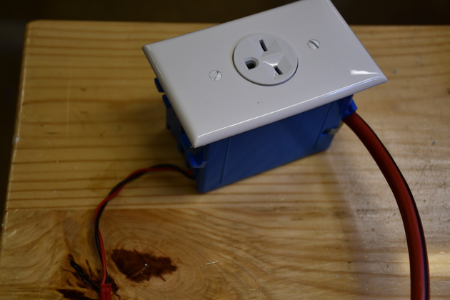
Here it is, ready to use. |
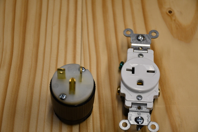
| The correct plug and recepticle (NEMA L6-20). |