CT Sensor
11/22/23: Page Origin
Very Dangerous High Voltages and Currents.
Use extreme caution when building and assembling these
CT Sensor Discussion
My old current sensor (Isnsr) used a ACS712, but I was ripping a 2x10 on the
3 HP Jet table saw when it pinched and the motor stalled.
The resulting current surge evaporated the link on the ACS712, which, fortunately,
stopped the saw's power.

After doing a little research, I decided to use a CT (current transformer).
This will provide much better isolation between high voltage, high current circuits, and the Arduino.

This meant, removing the ACS712, and filter and replacing them with the new CT and an op-amp filter rectifier.

BTW: I measured the 5V current drawn by the new CTsnsr at 400Ua, yes micro amps.
This means the new CT sensor can be powered by a 3rd wire from the system
controller, and eliminating the 5V power supply inside the CTsnsr.
I did, however, leave the mini 5V ps when I installed the new OpAmp Filter board
to save replacing the 2 wire cable with a 3 wire and modifying the existing 3 row header on the system board.

A thought: use 3 wire servo wire for the CTsensor, it is handy and plenty available.
Due to the low current, voltage drop on long runs (10 to 15 ft.) shouldn't be a
problem.
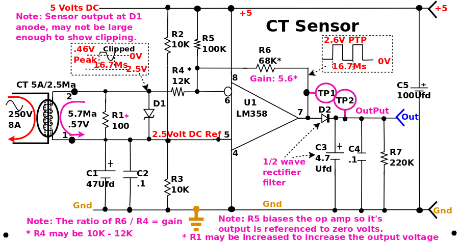
The new current sensor filter (CT Sensor) will use a CT (Current Transformer)
with a new op-amp rectifier.

In the diagram (above) you'll note, in the absence of the ACS712, I had to
establish a 2.5 V reference voltage with two 10K resistors (R2, R3) with filters
C1 and C2.
I also added a 5.6V 1W zener as a clipper and voltage limiter for the op-amp inputs.
Since the op-amp inverts, I clipped the positive excursion on it's input so it's
output would be positive.
I also added about 25Ua, via R5 into the summing junction, so the ouput would be
referenced to zero volts.
The op-amp's output should be from zero to 2+ volts.
Note to self: I need to add a duration factor (1 sec) for motor startup when
scanning current sensors for a running motor, to eliminate false starts of the
DC when running a low current device (like the Tormek).

If I get a positive reading from an CT sensor, wait .25 sec and check again
before calling it 'ON'.

Also: From: https://calculator.academy/motor-startup-current-calculator/
	I inrush = 4 * (RP / sqrt(3) * V * PF * E))
	I inrush = startup current (amps).
    RP is rated power(Watts).
	V = voltage (volts).
	PF = power factor.
	E = effeciency.
According to this, 3HP motor, 80% effecient, should draw 35.14 amps inrush.
Not LR (Lock Rotor) current.
E = Volts, I = Amps, R = Resistance, P = Power Watts
A little Ohm's law and power equation in the following lines:
	E=IR
	I=E/R
	R=E/I
	P = EI                   Power (Watts) = Volts x Current
	I=P/E
	E=P/I
	1HP = 745.7 Watts
| Tool
| HP
| Watts
| Volts
| Amps
|
| Jet Jointer (JJ-6CSDX) | 1 | 745.7 | 120 | 6.2
|
| Jet 12" Sander (JSG-6DCK) | 1-1/2 | 1118.55 | 120 | 9.32
|
| Jet 14" Band Saw (JWBS-14SFX) | 1-3/4 | 1305 | 120 | 10.9
|
| Jet Table Saw (Xacta 30") | 3 | 2237.1 | 240 | 9.32
|
| Bosch Miter Saw (GCM10GD) | ??? | ??? | 120 | 15
|
| Porer Cable Router | 3-1/4 | 2423.5 | 120 | 20.2
|
| DeWalt Planer JPM-13CS | ??? | ??? | 120 | 15
|
| Jet Ocs Sander (DBOS-5) | 1/2 | 372.85 | 120 | 3.1
|
| Jet Drill Press (JDP-17DX) | 3/4 | 559.2 | 120 | 4.66
|
| Jet 10" BandSaw (JWBS-10) | 1/2 | 372.85 | 120 | 3.1
|
| Power Matic Mortiser (PM701) | 3/4 | 559.2 | 120 | 4.66
|
| Power Matic Lathe (PM2014) | 1 | 745.7 | 120 | 6.2
|
To detect when motor is running:
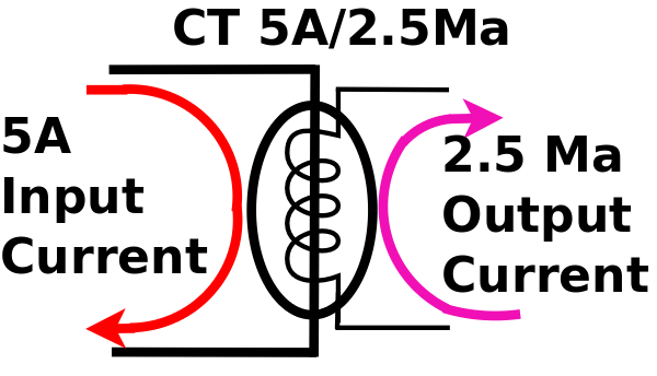
The CT, being 5A/2.5Ma (5/.0025) has a 2000:1 winding ratio.
Input currents in RMS, hence output current convert to peak.
 If I choose at least an 8Amp RMS run current, 8A/2000 = 4Ma RMS
output current. Since we need peak voltage, convert to Peak
current (not peak to peak since its half wave rectified).
4Ma RMS = .004 * 1.414 = 5.7Ma peak current.
Filter gain is 5.6, with an expected output voltage of 2.6V PtP (2v rectified).
2.6V / 5.6 = .464V input.
R = E/I, .464V / 5.7Ma = 81.4Ω (standard resistor of 82Ω).
Hence Rload (Burden) 100Ω.
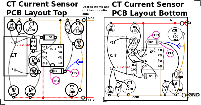
Parts List:
R1 100Ω
R2,R3 10K
R4 12K
R5 10o0K
R6 68K
R7 200K
D1 5.5V 1W Zener
D2 1N4001
C1 47 Ufd
C2,C4 .1 Ufd
C3 4.7 Ufd Electrolytic
U1 LM358 Dual OpAmp
CT ZMCT102 A 5A/2.5Ma
If I choose at least an 8Amp RMS run current, 8A/2000 = 4Ma RMS
output current. Since we need peak voltage, convert to Peak
current (not peak to peak since its half wave rectified).
4Ma RMS = .004 * 1.414 = 5.7Ma peak current.
Filter gain is 5.6, with an expected output voltage of 2.6V PtP (2v rectified).
2.6V / 5.6 = .464V input.
R = E/I, .464V / 5.7Ma = 81.4Ω (standard resistor of 82Ω).
Hence Rload (Burden) 100Ω.
Parts List:
R1 100Ω
R2,R3 10K
R4 12K
R5 10o0K
R6 68K
R7 200K
D1 5.5V 1W Zener
D2 1N4001
C1 47 Ufd
C2,C4 .1 Ufd
C3 4.7 Ufd Electrolytic
U1 LM358 Dual OpAmp
CT ZMCT102 A 5A/2.5Ma
|
|
CT Snsr
|
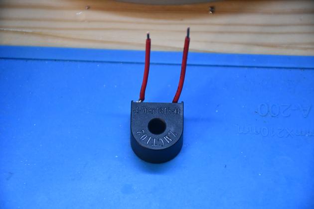
The CT (Current Transformer) I used on the new sensor.
It's available from Amazon for about $0.80 each.
Note this one has red leads soldered, I used it on my breadboard.
|
|
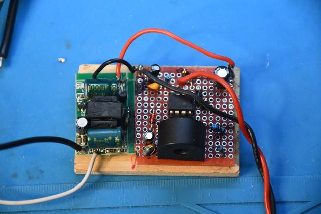
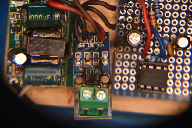
New CT Sensor glued to the base board.
The perf board is 1-1/2" x 1-1/2".
I have not run the 12 AWG wire through the CT yet.
I kept the little 5V PS (on the left of the baseboard).
|
|
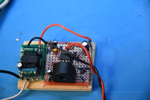
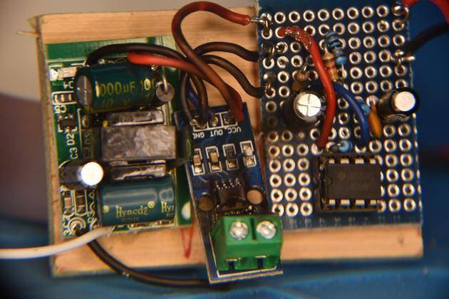
A little different angle.
Note the red/black twisted pair are the output to the system board.
|
|
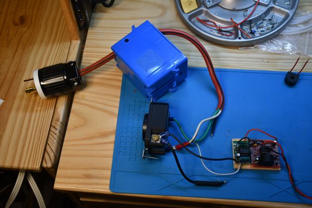
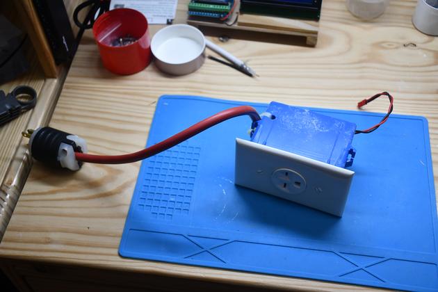
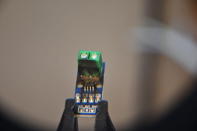
The entire CT sensor ready to assemble.
I still need to run the hi Voltage/Current wire (Black) through the CT's opeininig.
|
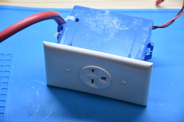
Old Isnsr
|
The old 240 Volt Current Sensor, removed from the shop.
|
|
Closer look, right side.
|
|
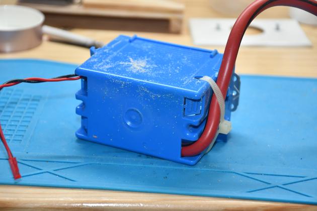
Back.
|
|
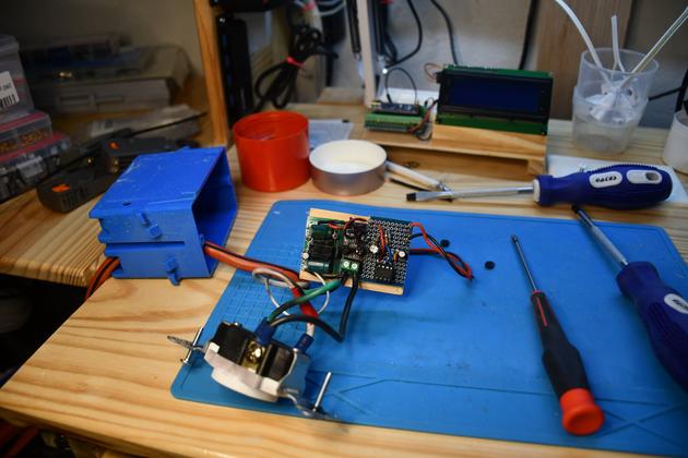
Opened up.
You can see all the main Isensor parts.
|
|
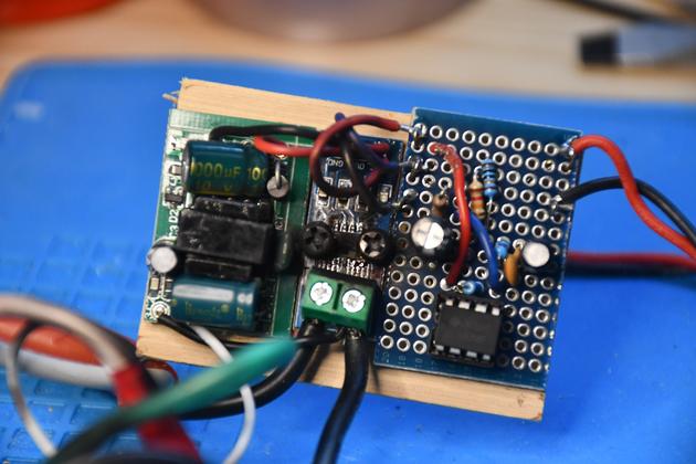
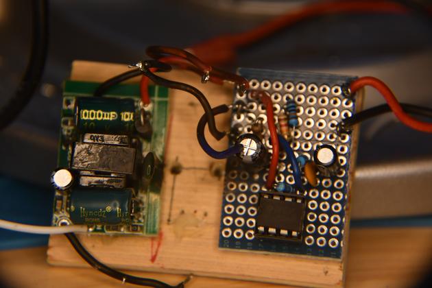
Closer look at the circit board. Note the area of the current sensor (center section) near the two high voltage current connections appears burned.
This is normally silicon glued to the bottom of the single box.
On the left is the 5Volt power supply, center is the Current Sensor, and right is the amplifier, rectifyer.
|
|
With the ACS712 unbolted, you can see the burned area around the ACs712 chip.
|
|
A little different angle of the sensor floating.
|
|
Bad things have definitely hapened to the ACS712 current sensor.
|
|
The base board with ACS712 removed.
|