What is a Current Transformer? From Wikipedia:
A current transformer (CT) is a type of transformer that is used to measure
alternating current (AC). It produces a current in its secondary which is
proportional to the current in its primary.
In our case, the primary is one of the conductors of the circuit that we
want to measure, and the secondary is the output jack that plugs into the
IoTaWatt.
So without connecting anything directly to any high-voltage wiring, it’s
possible to get a scaled down measure of the primary current that can be
used to passively measure power (Watts) of a circuit.
Types of CTs CTs come in various types, sizes, and capacities, and are made for a variety of end uses. This tutorial doesn’t try to address all aspects. That’s what Wikipedia does well. Here we’ll try to focus on the CTs that are suited to use with the IoTaWatt in typical scenarios. Physically, a CT needs to have an iron core through which one or more primary conductors pass. The most basic type is a solid-core CT, where an iron doughnut is wrapped with turns of wire. This type of CT is relatively inexpensive, typically very accurate, but requires that the primary conductor be disconnected and reconnected to install, thus exposing the installer to high-voltage and disrupting the primary circuit.
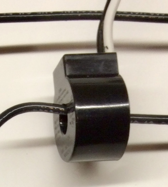 Solid Core CT
Split-core CTs also require an iron core around the primary, but do so using two
hinged halves that mate to form the continuous iron loop. This type of CT can be
installed by simply snapping the two halves over an active primary conductor.
Solid Core CT
Split-core CTs also require an iron core around the primary, but do so using two
hinged halves that mate to form the continuous iron loop. This type of CT can be
installed by simply snapping the two halves over an active primary conductor.
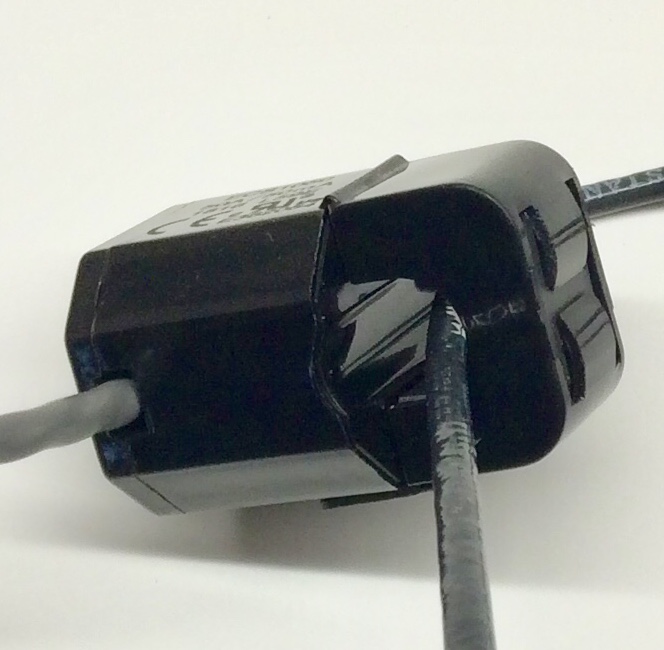 Split Core CT
Installation **Warning!** The installation of CTs can be dangerous and/or cause hazardous situations resulting serious injury or death. Worldwide, there are a variety of electrical conventions, regulations and standards. It is the user’s responsibility to insure that the installer is qualified and all local codes and regulations are followed. To measure the current in a circuit, a CT is installed on one, and only one, of the conductors in a circuit. Either the conductor is passed through the solid-core, or the split-core is clamped over it. CTs must have a load. Without a load, they will develop very high voltages that can damage the core windings and/or create a safety hazard. When plugged into the IoTaWatt, the secondary windings are loaded by a burden resistor. Some CTs have protective diodes, called TVS diodes, that will protect against damage when unplugged for short periods. Even if a diode protected CT is to be unplugged for an extended length of time where the primary is energized, the CT should be removed or shorted. Shorting will not damage the CT.
Polarity CTs are manufactured to produce a secondary current that is in phase with the primary current when installed with a particular orientation. In single and split-phase installations it is important to observe polarity in certain situations. In three-phase installations, it is imperitive that a polarity convention be observed. IoTaWatt will accept many different CTs from different manufacturers. While most have some type of markings that can be used as a reference for polarity, there is no universal standard. Typically, CTs from the same manufacturer will be consistent with respect to source and load indicators. And so it is for the Echun CTs that IoTaWatt, Inc makes available. When installing, we use the notion of a source and a load. The source can be conceptualized as where the power comes from and the load as where the power goes. So for the mains, or incoming power to a service, the source would be the meter side, or incoming power feed. The load would be the main circuit breaker or fuse side. For branch circuits, it would be just the opposite. The source would be the circuit-breaker side, and the load would be the appliance side. For a solar inverter connection, the source would be the inverter side, and the load would be the circuit-breaker or other point of interconnect.
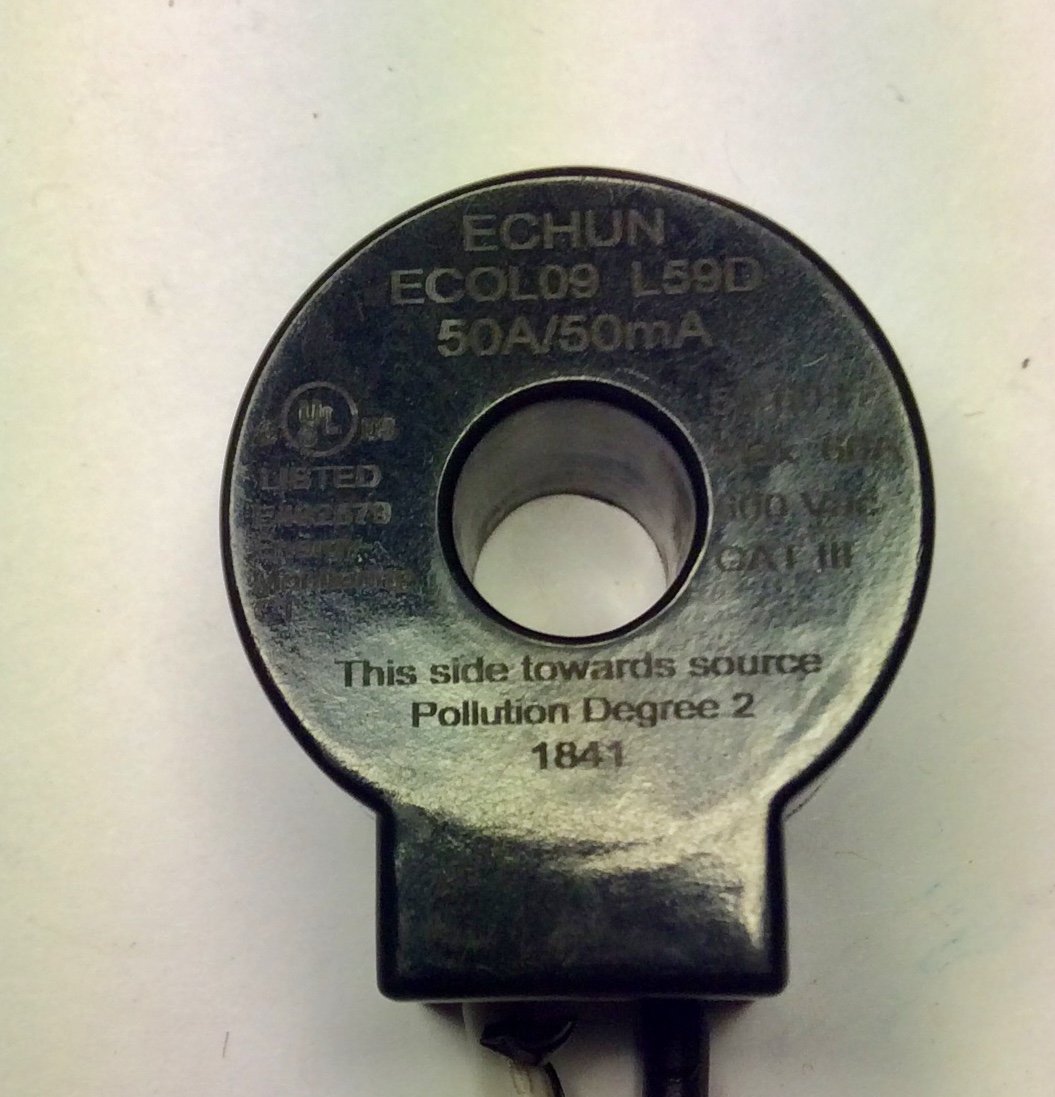 Here you can plainly see “This side toward source”
ECS1050
Here you can plainly see “This side toward source”
ECS1050
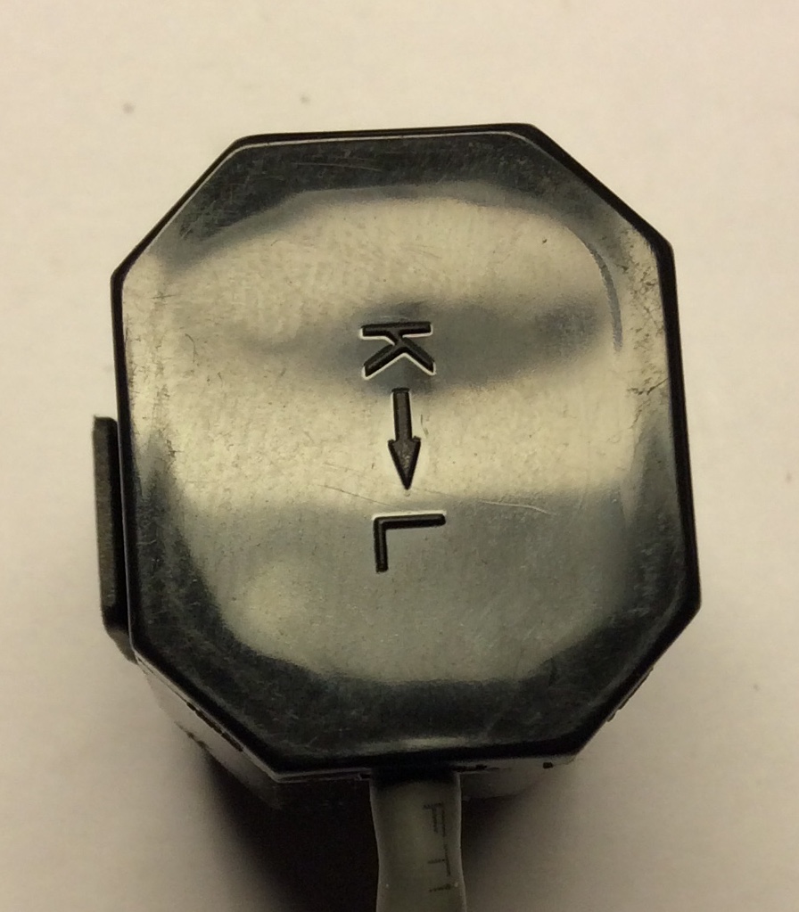 Here the arrow points source(K)->load(L)
ECS25200
Here the arrow points source(K)->load(L)
ECS25200
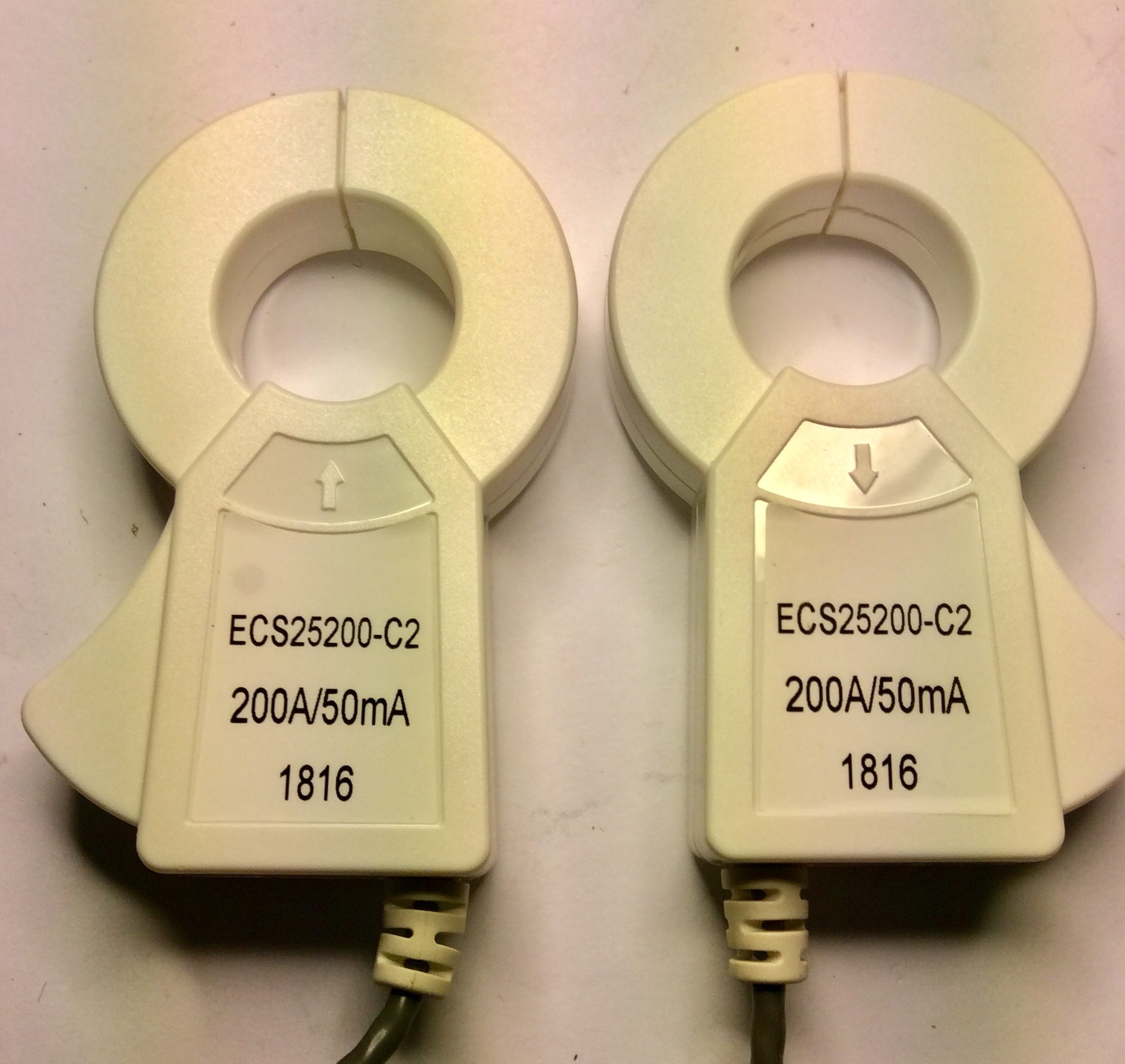 This is an Echun ECS25200 clamp type CT used for 200A mains. Both sides are
shown. Note the arrows just under the opening. The arrow pointing up to the
opening indicates the source side, and the down arrow indicates the load side.
This is an Echun ECS25200 clamp type CT used for 200A mains. Both sides are
shown. Note the arrows just under the opening. The arrow pointing up to the
opening indicates the source side, and the down arrow indicates the load side.
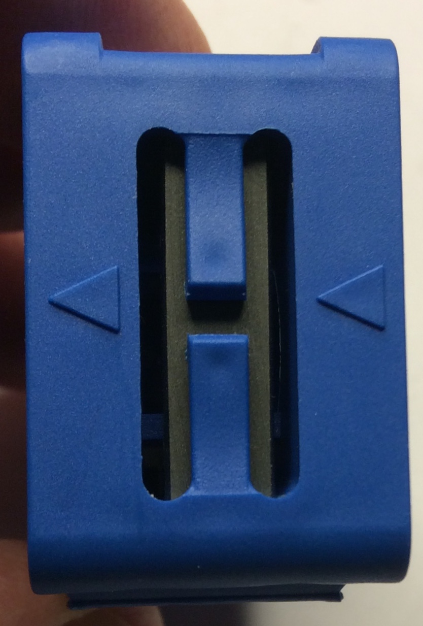 SCT013
This is the common SCT013 CT. If you are using them exclusively, the arrow can
be aligned consistently as source to load. But note that if using with the Echun
CTs, they must be installed with the arrow pointing from load to source. This
isn’t a fault of either manufacturer. It just reflects the lack of a standard
for how to connect the CT secondary to the 3.5mm jack used to connect.
SCT013
This is the common SCT013 CT. If you are using them exclusively, the arrow can
be aligned consistently as source to load. But note that if using with the Echun
CTs, they must be installed with the arrow pointing from load to source. This
isn’t a fault of either manufacturer. It just reflects the lack of a standard
for how to connect the CT secondary to the 3.5mm jack used to connect.
Single and three-phase systems All of the CTs in single or three-phase systems should be installed identically with respect to load and source. This is especially important when configuring three-phase systems using the Derived Three-phase method.
Split-phase systems Most of North America and some Asian countries use a split-phase power system with dual voltage, typically 120/240V. With this power system, there are two mains with exact opposite phase. The voltage between either main and neutral is 120V, while the voltage between the two mains is 240V. This provides an advantage of the relative safety of lower voltage in small appliance outlets, while still providing high voltage for workhorse appliances like water-heaters, ranges, and clothes dryers. In these systems, while possible to use two voltage references, typical IoTaWatt installations use a single reference that reflects the phase and voltage of one of the sides, or legs as they are commonly called. The result is that CTs on the other leg must be oriented the opposite way to be in phase with the opposite voltage reference. This can be accomplished by physically installing them reversed, or by installing all of the CTs the same way and checking the reverse box when configuring. There is more to installing CTs on 240V circuits in split-phase systems in the next chapter.
240V Split-phase circuits As explained above, split-phase systems can provide high-voltage for large appliances. These circuits are connected to two adjascent CTs that are on different legs. The usual convention is to use RED and BLACK wires or, as explained below, BLACK and WHITE for pure 240V circuits.
240V only When I say pure 240V circuits, I mean circuits that are usually a single load, and do not have a third neutral wire to use either leg independently for 120V. Examples of pure 240V circuits would be a resistive water-heater, well-pump, and baseboard electric heater. A common giveaway for these circuits is that they don’t have a neutral wire, and usually use two conductor with ground BLACK and WHITE leads. With these circuits, you can place the CT on just one of the conductors, and check the double box in input configuration, directing IoTaWatt to double the voltage value to report correct power and amperage.
120/240V circuits Like the pure 240V circuits above, these circuits use two adjascent circuit-breakers, but also have a neutral conductor. They usually have RED and BLACK conductors on the circuit-breaker and a white neutral conductor that connects to the neutral bussbar. Typical appliances are ranges, ovens, and clothes-dryers. Circuits feeding sub-panels are usually of this type as well. For these circuits, the two legs must be measured individually because the current in each is not always the same. There are a couple of ways to do this. The easiest way is to pass both the RED and BLACK conductors through the CT. A CT will measure the total current of all of the conductors that pass through the primary. But there is a twist. The phase of the current in each is exactly opposite the other, so they they will cancel each other out and rather than get the sum of the two, you can get the difference between the two. The solution is to pass one conductor through in the opposite direction to the other. There is a common trick for this. In most panels, the conductors are brought past the CT in a U shape so that there is some excess wire in case the circuit needs to be moved within the panel. You can use this U configuration to easily reverse one of the conductors. In this case, the CT needs to handle the combined capacity of the two circuit breakers when added together. An ECS1050 can probably be used up to about a 2x30A breaker.
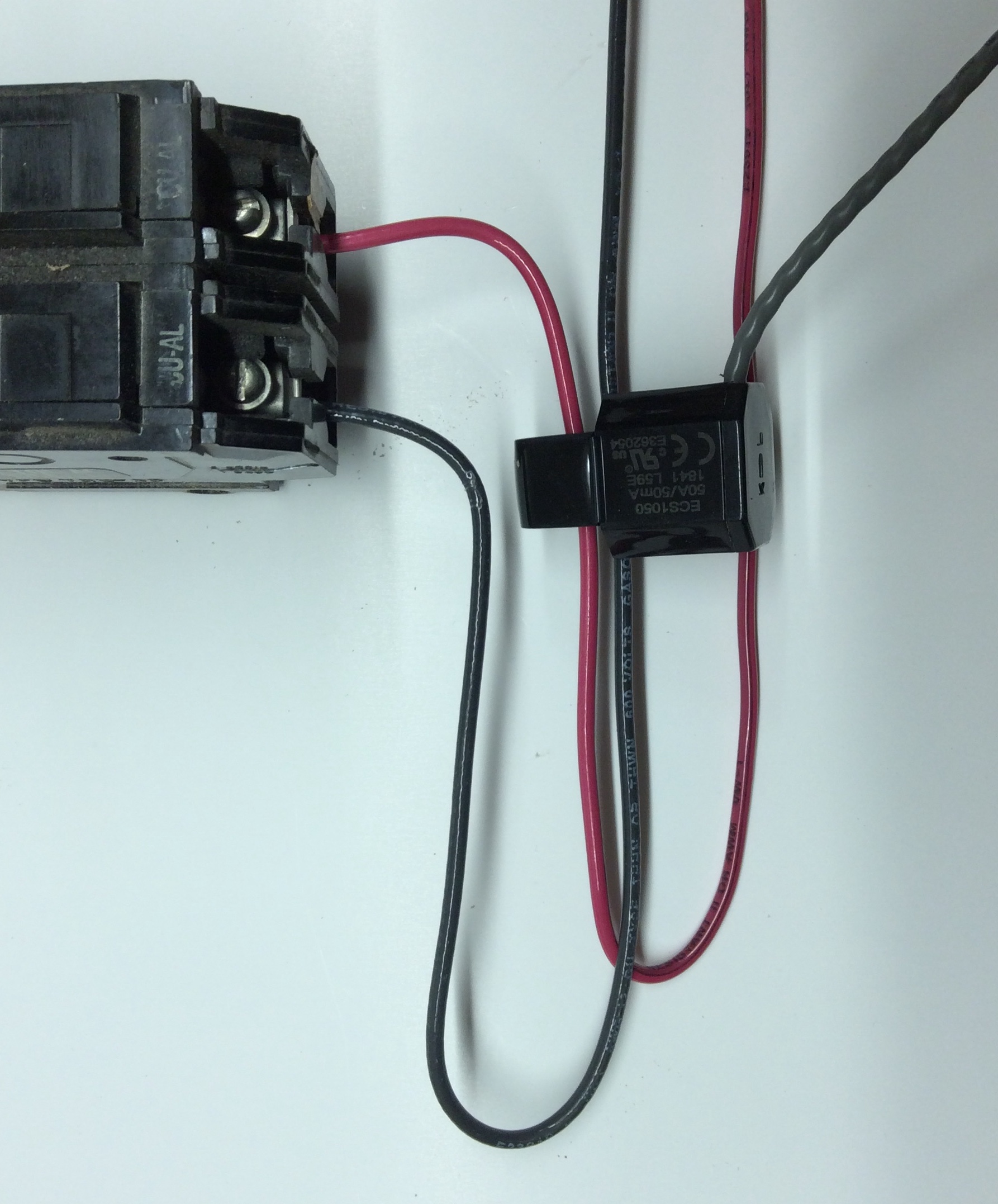 Reversed CT conductors
The CT is clamped around the RED wire going down and the BLACK wire going up.
An alternate method, and recommended with high amperage sub-panel circuits, is
to put a separate CT on each leg. The CTs can be connected to two individual
IoTaWatt inputs and added together later for the total. With this method, each
of the two CTs only need match the capacity of one of the circuit breakers.
Two individual CTs can also be combined with a common headphone splitter and fed
into a single IotaWatt input. When combining this way, both CTs must be the same
model with an individual capacity sufficient to measure the combined capacity of
the two circuit breakers.
Reversed CT conductors
The CT is clamped around the RED wire going down and the BLACK wire going up.
An alternate method, and recommended with high amperage sub-panel circuits, is
to put a separate CT on each leg. The CTs can be connected to two individual
IoTaWatt inputs and added together later for the total. With this method, each
of the two CTs only need match the capacity of one of the circuit breakers.
Two individual CTs can also be combined with a common headphone splitter and fed
into a single IotaWatt input. When combining this way, both CTs must be the same
model with an individual capacity sufficient to measure the combined capacity of
the two circuit breakers.