| 
| 
| 
|
| Blower Switch | |||
|
|
|
|
|
| Blower Switch | |||
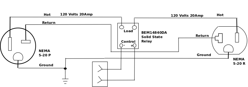
| Back So Automation | Diagram | Isnsr |
Very Dangerous High Voltages and Currents, use extreme caution when building these
In order for an Arduino to control a multi horsepower Dust Collector Motor I
have to use some kind of hefty relay.
I need a relay that can withstand the back EMF generated
by switching electric motors on and off.
Years ago my friend Herb Hanson found the Crydom SSR (solid state relays) for a
project we were working on at the time where we needed to control Bodine geared
motors.
Over the years I have applied several SSRs and am a real fan.

Amazon listed several and I chose the BEM-14840DA requires 3-32V DC to turn on
and will switch 24-480V AC 40a SSR (19,200 Watts) which cost $10.79 which isn't
bad considering you won't have to worry about it dying any time soon.
Found another SSR at Amazon.
SSRs are a little pricyer than the arduino relay modules but I've never had one
to crap out switching a motor, and they make some honkers that'll switch
anything.
These solid state relays can easliy be switched by an Arduino digital output and
can handle large motors.
I mounted the SSR in a double gang steel box with a 1' 3 prong, 14ga pigtail
(15A circuit) and a dual receptical.
My Dust Collector blower runs on single phase 120 Volts, so I only need one SSR.
In 2022, I upgraded the blower to a 2HP Jet motor. Please see Blower Upgrade
Back EMF (As I remember, EMF stands for ElectroMotiveForce)
Is the voltage generated by a rotating motor that counters the voltage being applied, preventing the motor from appearing as zero impedance (like a short).
When you switch off the AC voltage that is being applied to and spinning inductive load (like the motor windings) the generated back EMF, no longer having anything to absorb it, springs back in nearly equal voltage that was being applied.
Remember, a 60 cycle 120 volt AC voltage cycles from zero, to +Hi 169, to zero, then to -Lo 169, and back to zero again.
120 Volt RMS, 60 Hz sine wave
+ Hi equals: +169 volts Please excuse my poorly drawn sine wave.
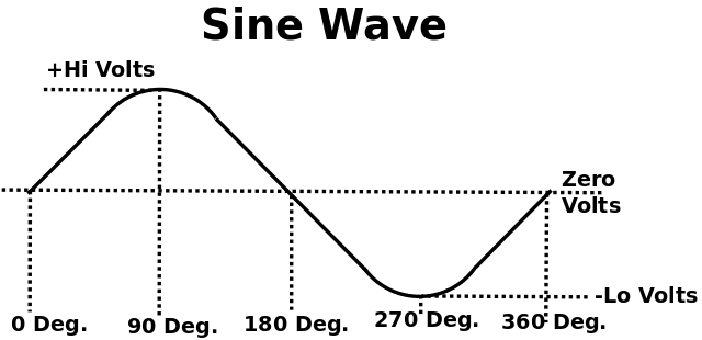
If you suddenly turn off the voltage (opening a switch), while it is at one of these peaks, nearly double the voltage (300 + volts) will appear on the winding connections of the motor caused by the EMF stored in the motor coils as it springs back.
A mechanical switch will tend to arc over as the high EMF voltage is reflected back whild the contacts are close together (in an attempt to break the circuit).
If you turn off the motor while the voltage is near zero, very little back EMF will be seen.
This is why a mechanical relay will appear to work for a few times before the contacts are welded or vaporized.
An SSR, when de-energised, waits for the voltage to be near zero before actually breaking the circuit.
OverCurrent
A second issue with SSRs is trying to put more current through it than it is rated for.
When the power is first applied to a motor, the motor is not turning so no back EMF is being generated.
This means the motor only has it's windings resistance to limit the current, hence a large current is being drawn.
As the motor begins to rotate, back EMF is being generated, increasing as the motor rotational speed increases, until the motor reaches it's max RPM and the back EMF stabilizes.
Ever notice how the lights in the room dim for an instant when you turn on a vacuum cleaner?
|
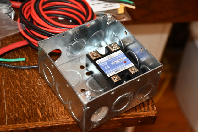
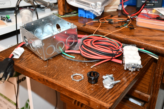
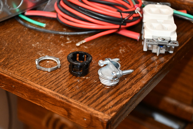
Parts for the switch (cover is in the background). |
|
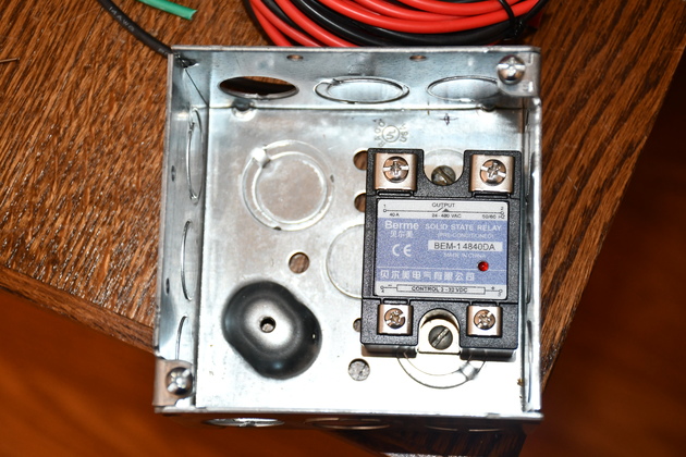
I used a double gang metal box for switch housing. Metal box acts as a little bit of a heat sink, but because this is a high current SSR (40 AMP) it should have a lower resitance and doesn't develop as much drop (E=IR) and generate much heat with a 1-1/2HP motor (P=EI). Drilled two holes in the bottom and bolted the solid state relay in. |
|
|
A little different angle, you can see tht two knockouts missing for the cable grommet and plastic grommet for the control wire. |
|
The two different type grommets. |
|
|
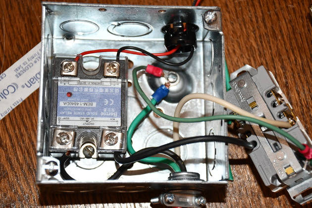
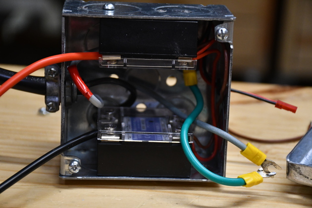
Everything is wired. Note the black wire from the pig tail, lower right, goes to the SSR, then another black wire goes from the SSR's other output terminal to the receptical. The white wire from the pig tail goes straight to the receptical, and the green wire goes to the recptical and a ground screw in the case. If this were two phase 240 Volt, you would need two SSRs and a different receptical. Lastly, the small red and black wires at the top go to the DC on output of the DustAuto controler. |
|
|
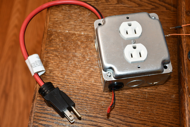
Completed Dust Collector switch. |
|
Different angle, you can see the conrol wire/plug a little better. The 120V pig tail is in the foreground. |

|
|
|
|
|