|
|
|
|
|
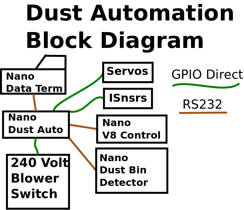
Dust Collector Automation Electronics
| |||
|
|
|
|
|
|
Dust Collector Automation Electronics
| |||
| AnaMux | Servos | Diagram | System cabinet |
| PCB | Isnsr | Sketch | Data Terminal |
There are probably many better ways to do this, but I'm old school and am comfortable with building things on perf board.
I'll use the same approach to layout as I did with the data terminal, that
is, use a breadboard (copper clad perfboard with holes on .1" centers).
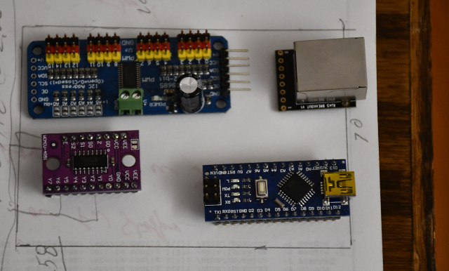
Also similarly, this PCB will have only 3 active electronic components,
nano, analog mux, and servo driver, plus lots of connector pins.
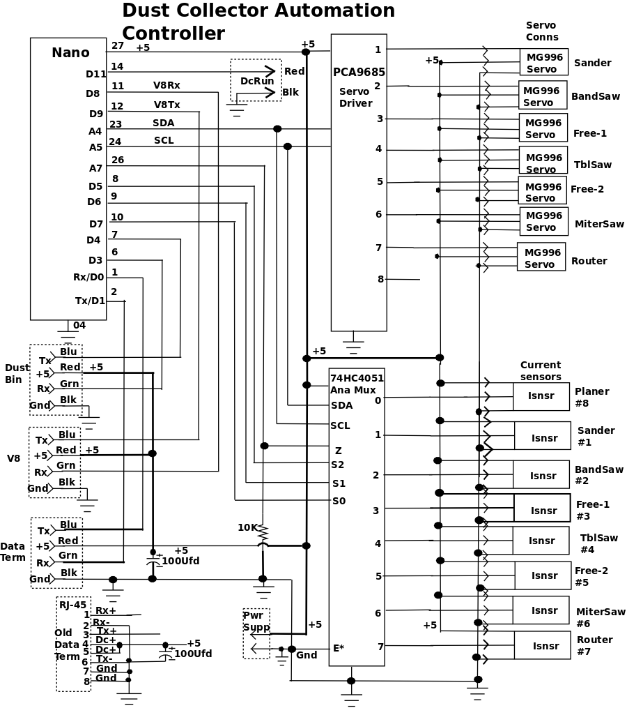
There will also be 8 places to plug in current sensors from the various
machines in front of the analog mux.
Isnsr 8 will be plugged into the sensor 0 position, the software will
accomodate this by throwing away the 8 bit when addressing the mux.
Think of it like a truncation.
There will also be a RJ-45 for the data terminal, and a 5.5mm 5V power
plug.
I'll mount the PCB in a small wooden box, probably attached to the ceiling.
PS:
Later I added two 4 pin headers, one for DustDetector2 and one for Valve8.
I'm going to abandon the RJ45 (ethernet cable) and move to a 4 pin JST
connector and 4 pin flat cable, this will reduct the cost and simplify
construction.
Also I'm going to move the Data Terminal's computer PCB from the side to
the
base board to improve access.
The system has 2 missing Isnsrs (the 1 and 2 Free). When I was testing the system, I found that when I had an active Isnsr, and as the analog mux scans across it's inputs (normally from Isnsr's) and found a missing sensor, the system thought the missing Isnsr was hi also, and would open it's valve and turn on the DC. The next scan found the real 'on' I snsr and toggled between the active machine and missing Isnsr. With the oscilloscope on it and discovered the high impedance of the analog input to the Nano, wouldn't discharge the voltage from an active Isnsr, so I had to add a 10K pull down resistor to the Z input.
The system runs off the lighting circuit in the shop, its only on when the lights are on. The sysem needs a fair amount of current, so I ended up using a 5Volt 8Amp power supply, 6 Amps would have done it but Amzon didn't have 5Volt 6Amp supply. I tried a 4Amp supply but if I turned the lights off and back on (or a power glitch), the system would crowbar the supply and then went into a kind of oscillation of full voltage then crowbar. I'm guessing the system or the PCA9685 would try to move more than one servo at a time, each servo is capable of drawing a little over an amp. More amps solved the problem.
Click for larger pics |
|
|
|
|
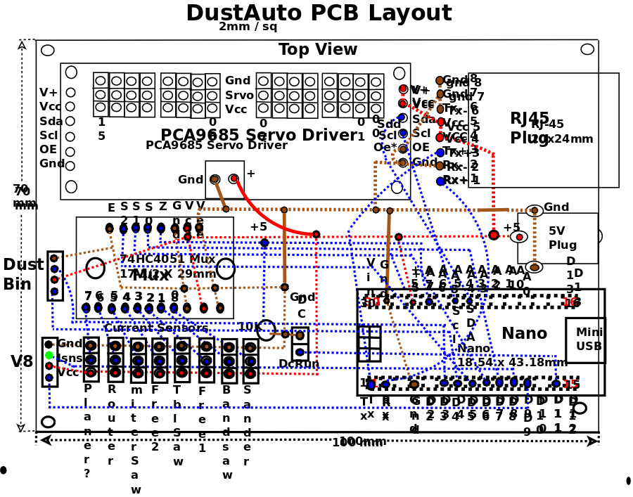
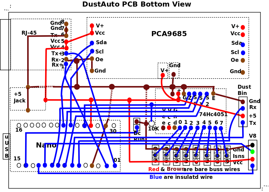
Not being a professional draftsman (although I have known some gem dandys), here is how I did the PCB layout. I realize this thing doesn't have the density of wiring of most devices so, I drew a box the actual dimensions of the PCB then arranged the devices on it. Only thing missing is the current sensor pins and the power plug. |
|
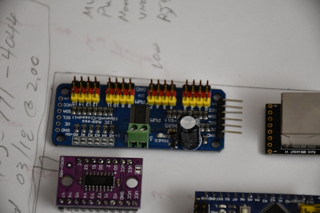
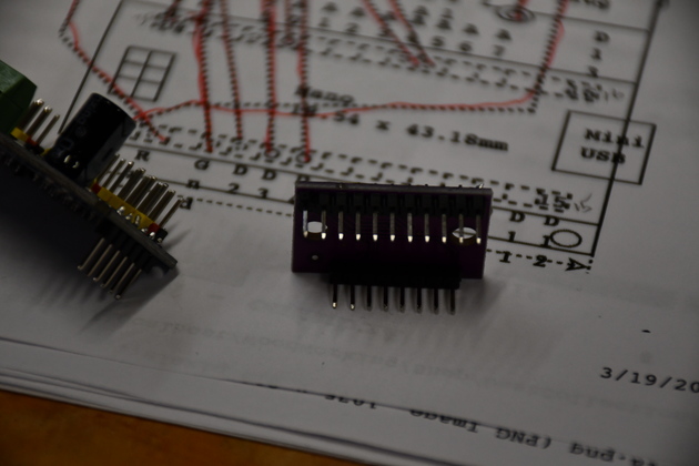
A little closer look at the 16 channel servo driver, it still has the 90° pins on the right end (I assume this was done in order to daisy chain the boards), but I'm going to plug this into the PCB. WIth 8 servo cables attached, I don't want the board waving around in space. I don't know what folks do with 16 servos attached to this, it must be very unstable. So i'll remove the right angle header and solder a straight 6 pin header into each end. |
|
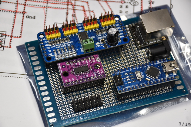
All headers and connectors in place.
The two 6 pin headers top left are for the 16 channel servo driver.
The eleven and 8 pin headers left center are for the analog mux.
The eight 3 pin headers below the mux are for current sensors.
The two 15 pin headers lower right are for the Nano.
|
|
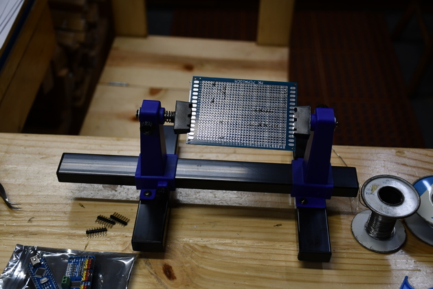
Pcb soldering headers, power, and ground. |
|
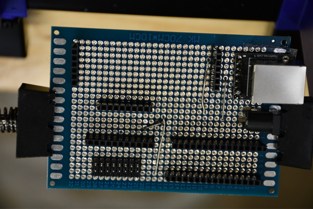
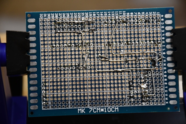
Bottom of the board. All headers, power, and ground soldered, ready to connect signals. |
|
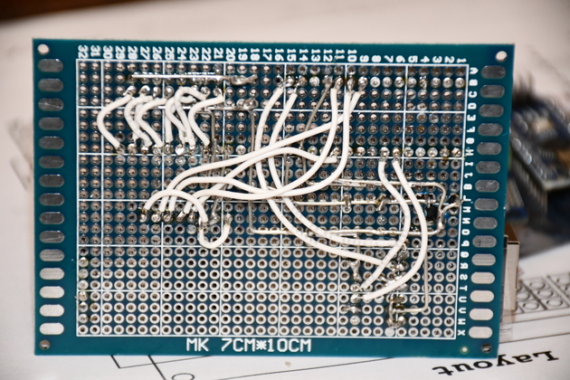
All the signal wires soldered in. |
|
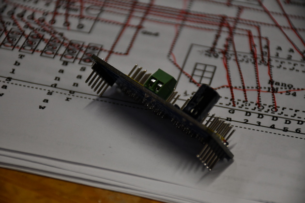
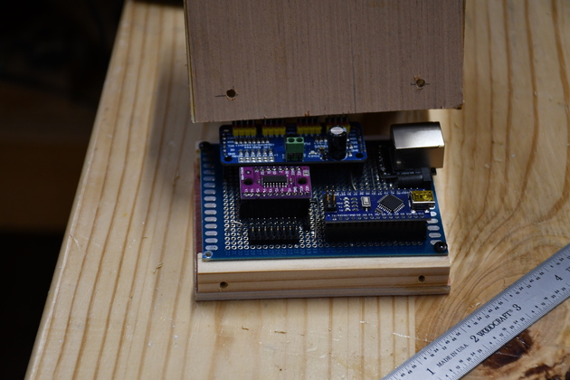
The 16 channel servo driver with new headers pointing down. |
|
The analog mux with it's headers soldered in. |
|
|
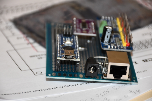
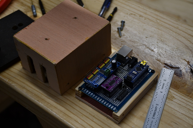
Control board with all components plugged in, ready to test. I haven't added the pins for the Blower's DC on cable. I also haven't added the 10K pull down resistor for the analog input. |
|
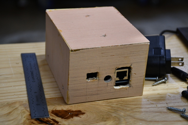
Connector end. |
|
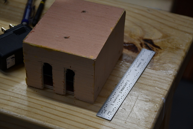
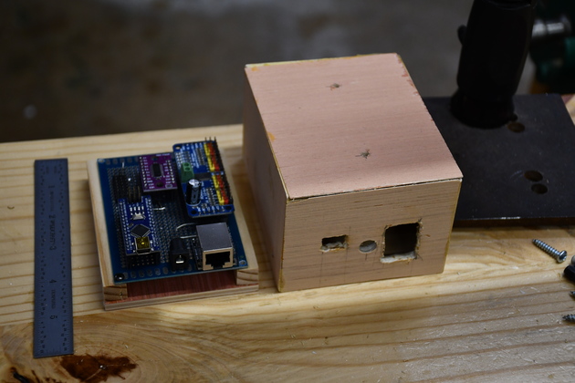
Front of system cabinet, again the pink plywood. I know it's ratty looking but it works well. |
|
System cabinet rear, showing slots for servo cables and sensor cables. Made of 3/16 plywood, I build these small cabinets like the storage bins, I miter the corners and glue, so there is no plywood edge showing. |
|
The cabinet's rear beside the system control board on it's base. Note the control board is mounted on the cabinet base. |
|
Cabinet front with the system board mounted on it's base. |
|
You can see the screw holes that fasten the cabiet to the base. |
|
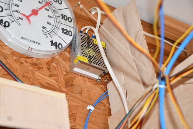
The power supply mounted high on the wall, next to the thermometer. This is actually a 5Volt 8Amp supply, I couldn't find a 6Amp switcher. It's input AC is from the lighting circuit, system is only on when lights are on. The power line from the power supply to the system control board is two 16AWG strands, a little over 2' long, this will give about 50Mv drop at 4Amps. The system draws about 1 amp in IDLE mode, and up to 1 more amp when moving a servo. Sometime at power up or during a power glitch, the PCA9685 will try to move several servos at once (each servo can draw over an amp) the supply crowbars, hence the 6 Amp supply. |
|
|
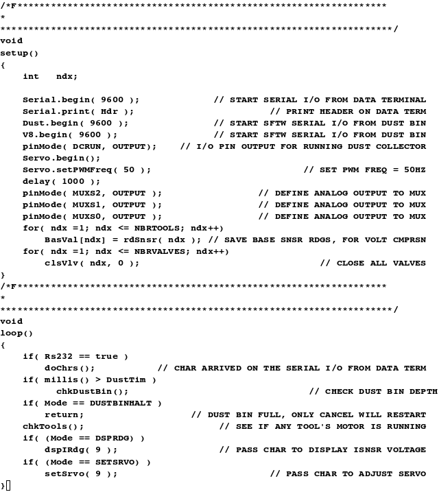
The system control board with most things plugged in.
The red plug just behind the Nano goes to the blower switch, the other red
plugs are from Isensors.
The 4 wire flat cable is to the dust sensor, the RJ-45 with blue cat-5
cable
goes to the terminal.
The black power plug with white cable comes from the power supply.
|
|
|
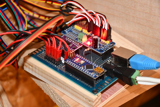
Control Terminal showing the system powered up, in IDLE mode. Note the [Dust Space: 25"] at the bottom, this is the remaining space in the dust bin. When this goes below an adjustable level the system goes into [Dust Halt] mode and shuts down the dust collector blower. |
|
Terminal swiveled right. You get a better look at the swivel. The swivel allows me to be in different parts of the shop and still see whats going on with the dust collection system and make changes. |
|
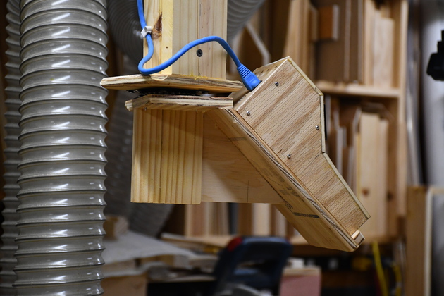
Sander updraft valve opened by the servo. |
|
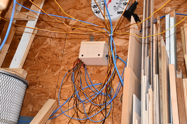
The system controler mounted against the West wall, below the thermometer. I know it looks like a rats nest, with 8 servo cables, 5 sensor sensor cables, Data Terminal cable, dust sensor cable, and DC on cable, but I'll see if I can't clean it up a little more. |
|
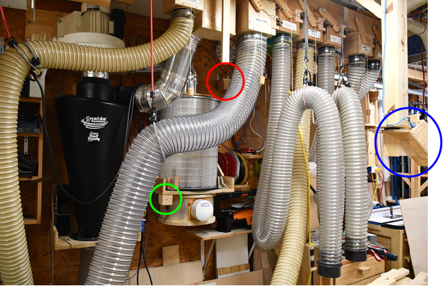
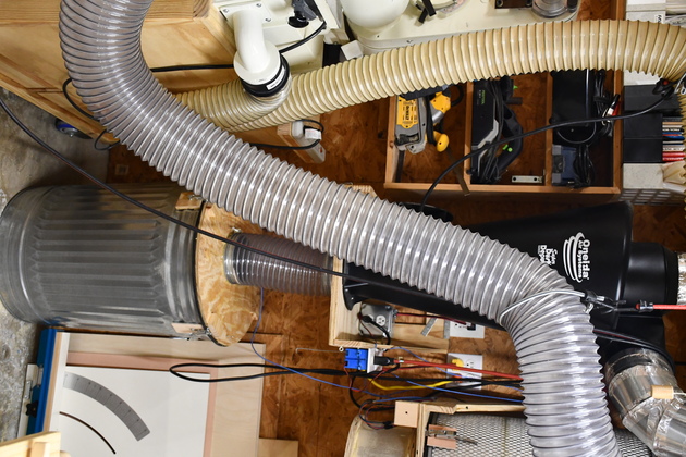
Most of the 6" dust collection system. The DustAuto controller is in the RED circle, the Dust Sensor is in the GREEN circle, and the Data Terminal is in the BLUE circle.
|
|
The cyclone and the dust bin below it. You can also see the blower switch on the cyclone shelf, in back right, and Isensors for sander and Bandsaw attached to the right of the cyclone shelf. To the right, you can also see the dust detector beside the filter clean -out box, below the filter. |
|
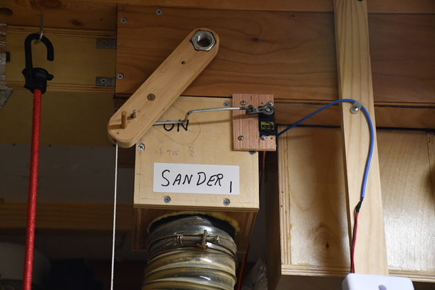
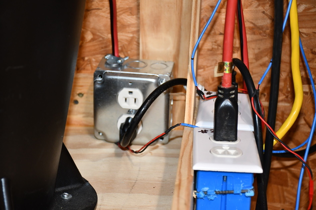
Better look at the blower switch and two Isensors on the cyclone shelf. The two Isensors are for the sander and bandsaw. |

|
|