|
|
| Construction of Southwest Ammo Die Plate Rack with Base | |
|
|
|
| Construction of Southwest Ammo Die Plate Rack with Base | |
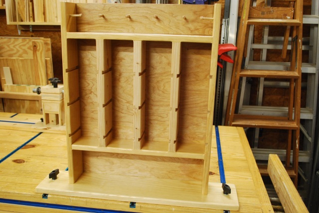
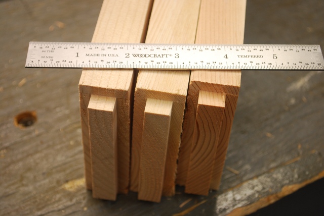
This Die Plate Rack is designed to fit into the tee tracks on one of my loading benches. The frame for this rack uses all mortise and tenon joints. The tenons are 3/8" tall, by 1/2" wide, and 3" long.
| Cutting Frame Pieces | Frame Assembly | Making Pegs |
| Diagram Page | Mortise and Tenon Page | Main Die Plate Rack Page. |
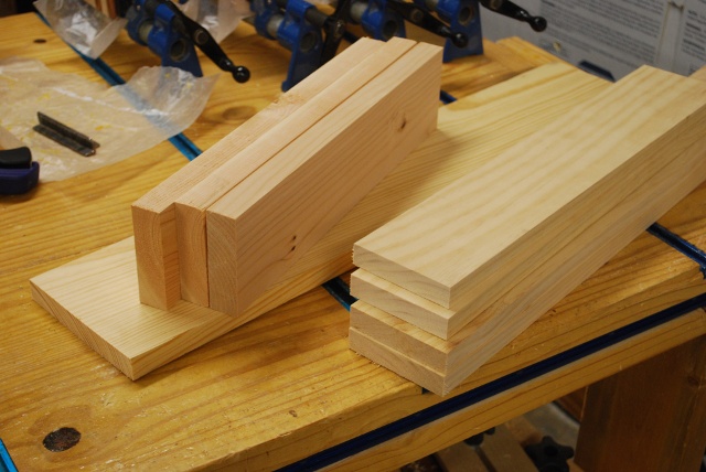
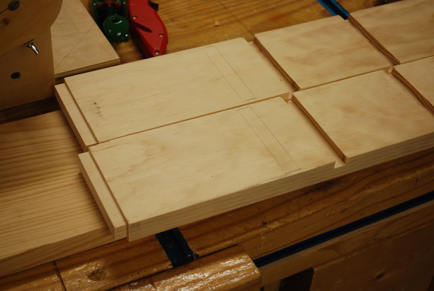
| Frame pieces cut to length and inside verticals resawn to 1" thick. |
| first shoulder cut on 1x4 tenons. |
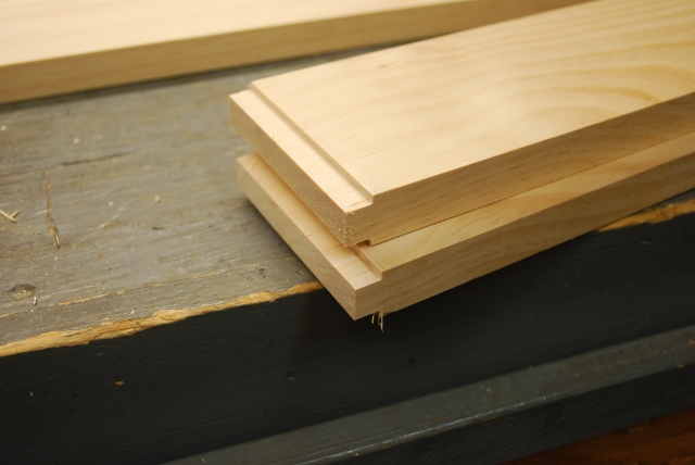
| Tenons cut on machined 1" thick center verticals. |
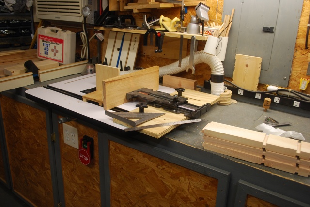
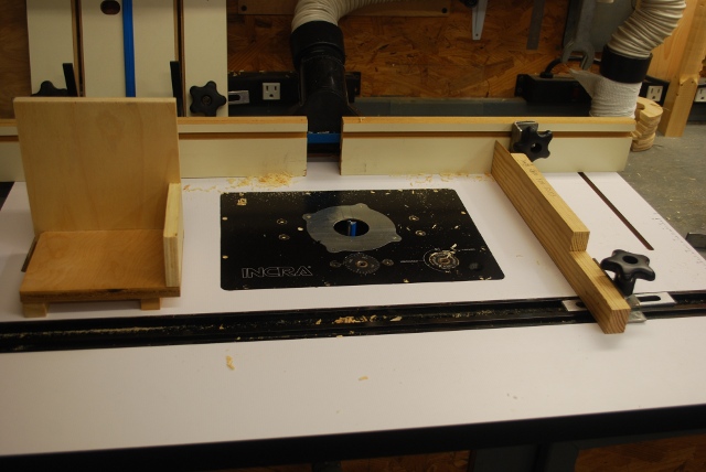
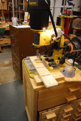
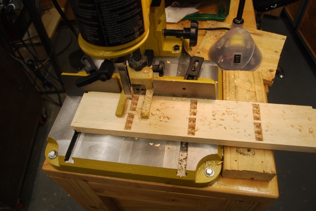
| Using my Incra Positioner to cut most of these tenons. I had to use the old slot cutter for some since they were so far from either end of the vertical. |
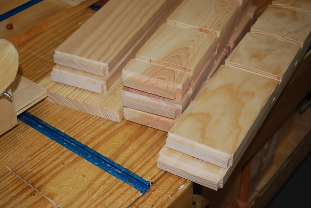
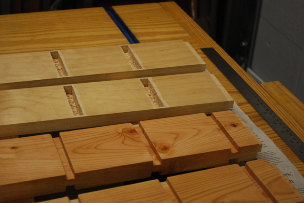
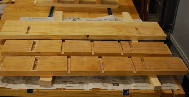
| Slots and tenons cut. |
| I had to use the old slot cutting jig on the side verticals, the Incra doesn't allow enough length for the center slot. |
| Cutting mortises on inside horizontal. Link to my mortise and tenon page. |
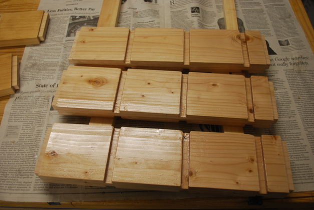
| Nearly finished. |
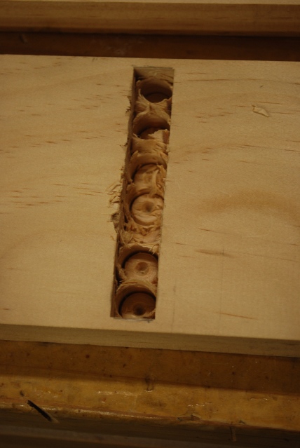
| Closer look at drilled mortise, ready to clean out with chisel. |

| Mortise cleaned out. |

| Inside verticals and horizontals being painted. |
| Horizontals (top) and center verticals, notice I didn't paint around the mortises (need to glue there). I'm painting inside the slots, its easier to do before I put it together. |
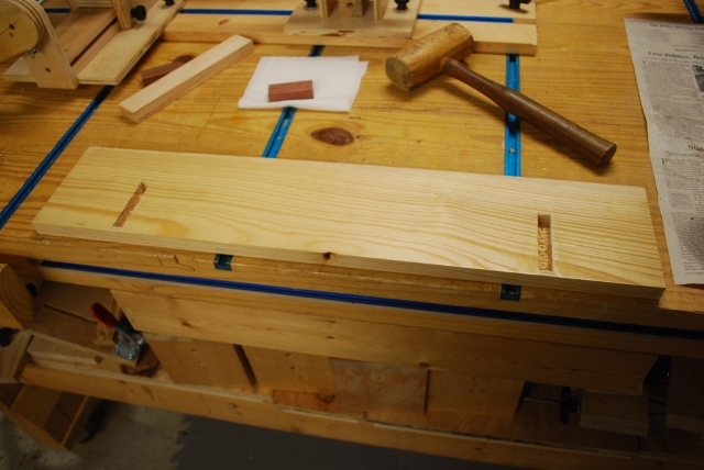
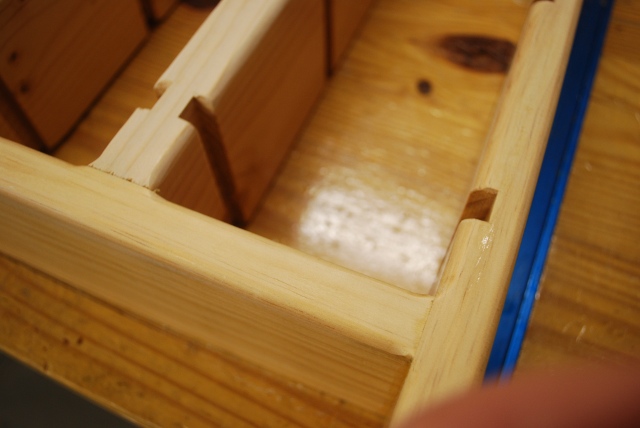
| Slots cut in outside verticals. You can just see where I've marked for mortises just to left (below) of slot. the tenon on the left end (bottom) will go into mortise on the base. |
| Base and outside verticals being painted. |
| Center verticals being painted. |
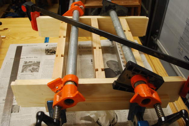
| Center verticals being glued to top and bottom horizontals. The diagonal clamp is to hold it square while the glue sets. |
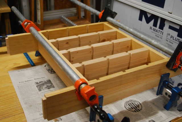
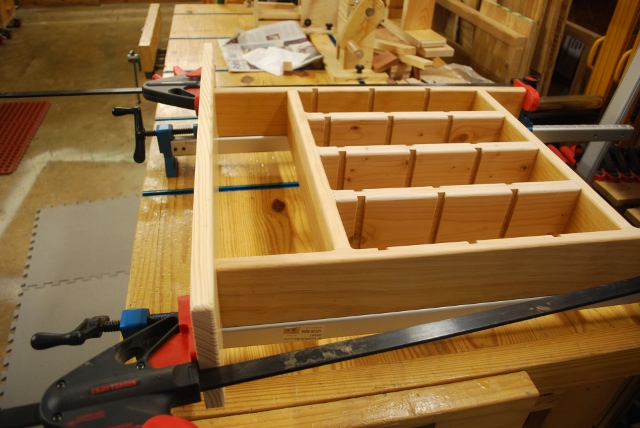
| Side verticals being glued to center section. You'll notice the tenons on the left (bottom) of the side verticals. |
| Base being painted with matching mortises for bottom of verticals. |
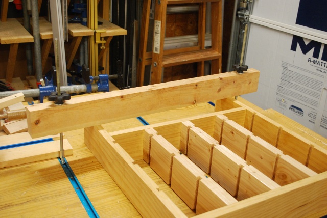
| Frame clamped down to round front corners. |
| Front corners rounded, I used a 1/4" round off bit with a bearing in the Bosch Colt. |
| Closer look at rounded corners. |
| Base being glued on. |
| Base bottom painted. |
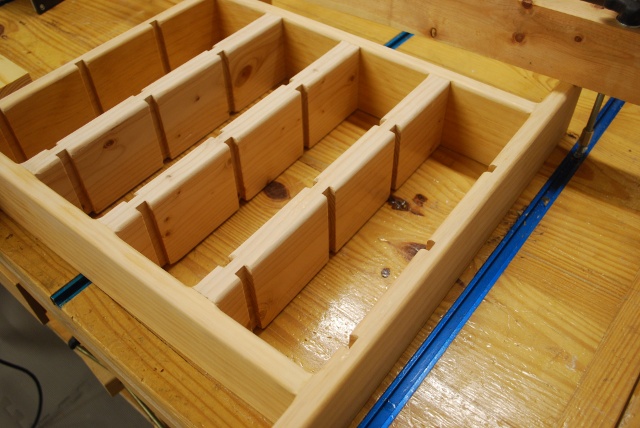
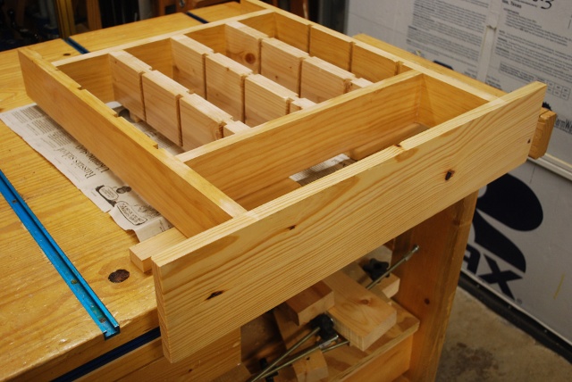
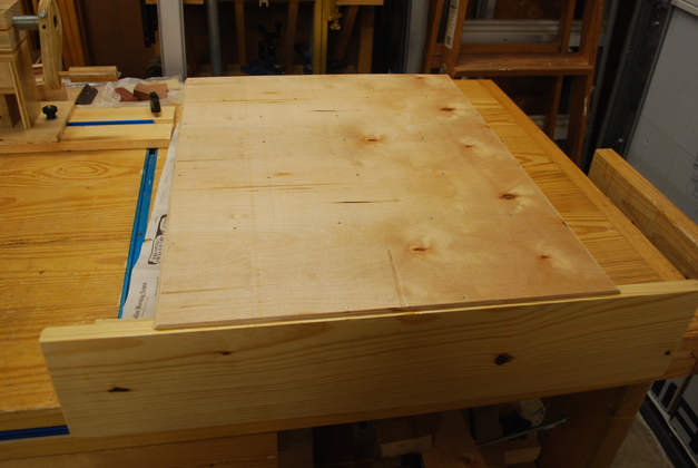
| All assembled except back and pegs. |
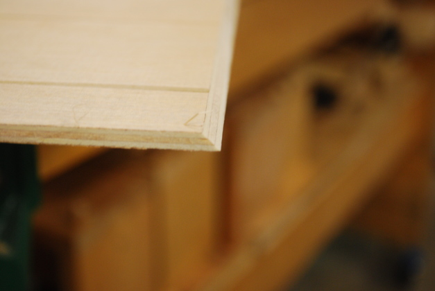
| Side of 3/16" back panel chamfered at 45°. Since the back panel will stick out (not in a rabbet) I thought I would chamfer the sides. |
| Back being glued on. |
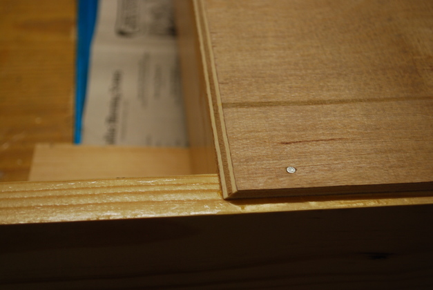
| You can see how the chamfer of the back panel works out. You can also see one of the wire nails I used to hold the back panel down while the glue sets. |
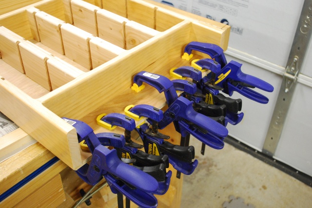
| Double panel clamped as glue sets. This upper area will support shell plate pegs so I double up on the panel. |
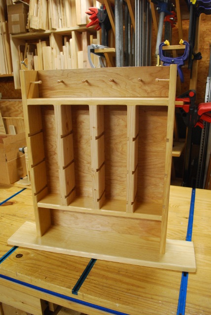
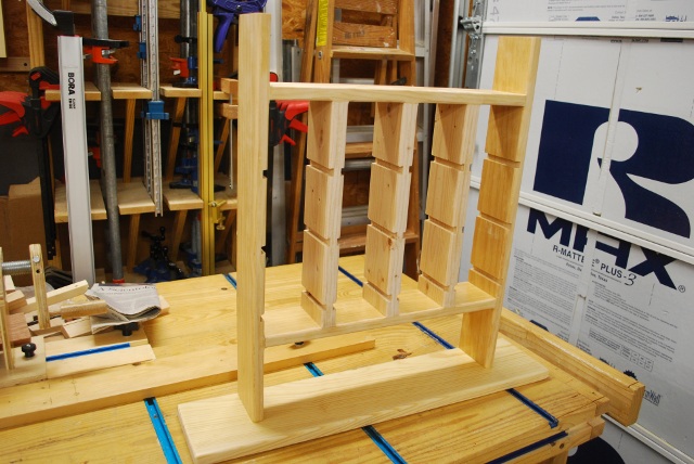
| Nearly done. |
|
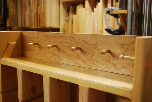
| All 6 pegs installed |
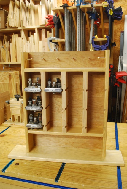
| With a few die plates. |
|
| Tee bolts and nuts installed |
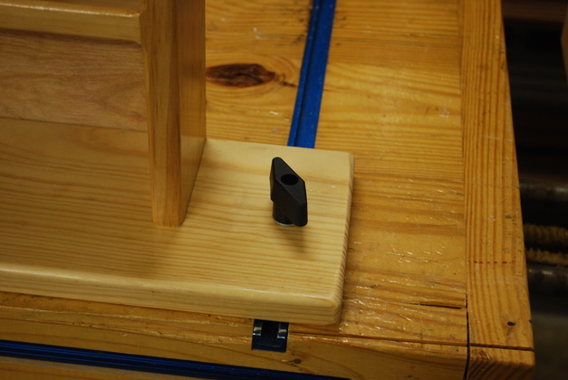
| Close pic of tee bolt and nut. |
|
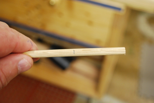
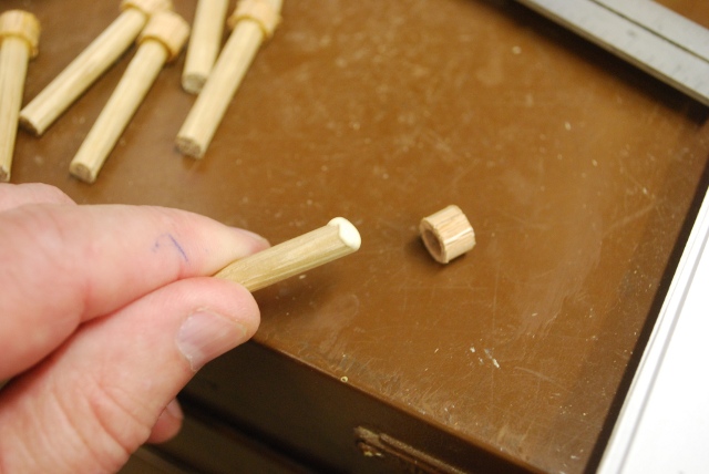
I want oak pegs to hold the shell plates so I'm stuck with 1/4" pegs with 3/8" caps.
1/4" oak dowel marked at 1-1/2" for sawing. After I sawed it off, I used a piece of 100 grit sandpaper flat on the bench to chamfer the sawed edges. |
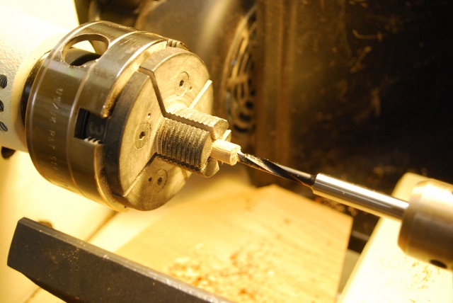
| This is a 3/8" oak dowel chucked up to have 1/4" hole drilled 1/4" deep. This will be the cap on top of one of the pegs, the cap keeps the shell plates from slipping off. Link to my page on making pegs like these. |
| Center 1/4" hole drilled. |
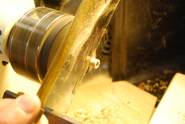
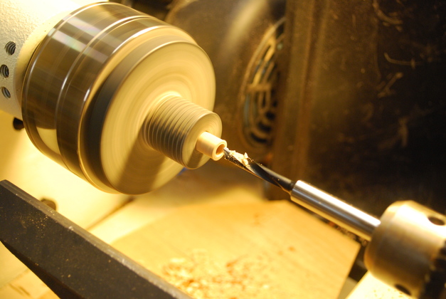
| Sawing off cap. The lathe is turning very slowly, I gently move the saw back and forth to clear the sawdust from the kerf. A hacksaw will work well for this also. |
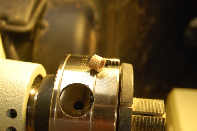
| Sawed off cap. |
| Glue on top of peg. |
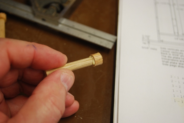
| Cap pushed on, now I wipe off the excess glue and let it dry. |
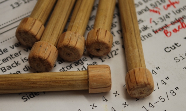
| Pegs after sanding in lathe, 3/8" oak caps on 1/4" oak pegs. In the background is the diagram for this project, please notice how I redline changes I need to make in order to improve the doc (I do the same thing with program listings). |
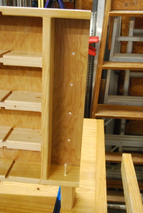
| First peg being glued. The other holes are already drilled. |
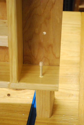
| Closer pic of first peg. |