For some time I have wanted to communicate with multiple devices (usually Arduino based) in my shop and house.
So far I have used RS232 for inter-device communications but, Arduinos have a limited number of ports so I'm restricted in the number of other hosts I can communicate with.
I would also like to be able to communicate with these devices from our networked computers.
RS-485
Appears to be a good medium that has good distance and can address many devices.
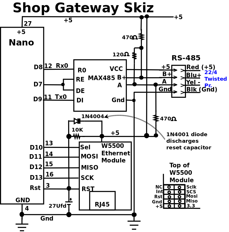
I'll use AltSerial to drive an RS-232 port on the Nano, then feed the RS-232 to a (MAX485), level shifter, to drive a shielded twisted pair 4 wire cable to remotes.
The RS-485 line will be run half-duplex, possibly with polling to allow any remote to initiate a request to other remotes or a network server..
GateWay:
A gateway between the in-house ethernet network and a new RS-485 network in the shop.
The gwy will run on a Nano with an Ethernet Module, use AltSoftSerial, and a RS-485 adapter interface as the master of a RS-485 network in the shop.
TCP packets will only contain ascii characters, including an 8 char Info header, containing a 4 char packet length field and 4 extra bytes followed by an abbreviated slave name ("EN" environment, "AC" for mini-split thermometer, "DA" dust automation.
The gwy will use RS-485 for communicating with the devices (slaves) in the shop: Env, DustAuto, Shop AC thermostat (mini split AC), and Sprinkler System.
The RS-485 devices will be using ascii characters with a crunch (#) followed by a 2 digit destination host number and any arguments required by the slave.
RS-485 messages will contain a small, initial vector address which will enable gwy to determine the message's destination.
When a request arrives it will be forwarded to the correct server, wait for the response, and forward the response back to the sender on the ethernet network.
In this 1st version, during the processing of the request no other requests will be accepted, since most of these request take minimal time (ENV query takes < 3ms).
Requests and responses should be very quick, only tying up the gwy for a few MS.
NOTE:
Arduino has come out with a Nano Ethernet Shield and a Nano 485 Shield.
Now if you can stack the W5500 based Eth Shield, 485 Shield, and a Nano, that would solve the mounting/PCB problem, and should work great!
Only promlem is $$$$$, $26.40 for the Eth Shield, and $45.49 for the 485 Shield. I'll just have to wait for them to come down in price.
I did a lot of experimenting on different Arduino ethernet devices before I laid out the PCB.
Build:
I used a prototype PCB from Amazon.
.
I trimmed the PCB to size, soldered the in-line headers, used 18awg tinned copper buss wire for the ground and vcc, then wired the individual signals with 26AWG insulated wire.
I'm currently working on the message protocols.
RS-485 messages will all be in ASCII to keep things simple and avoid need for htonx and ntohx() functions.
02/08/22: Page Origin
| | |
|
|
|
| Click For Larger Pic
|
Testing
|
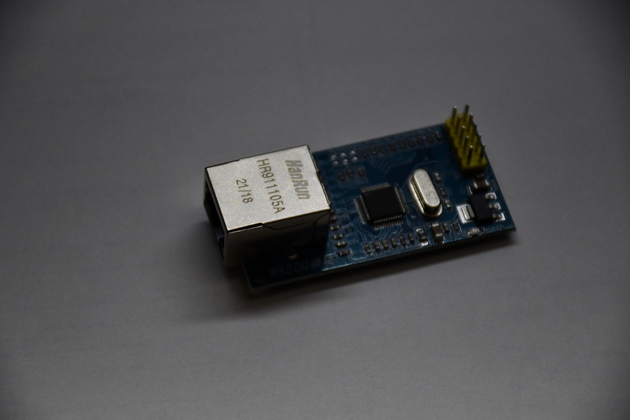
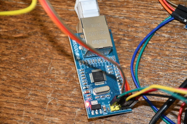
A closer look at a W5500 Ethernet Module.
|
|
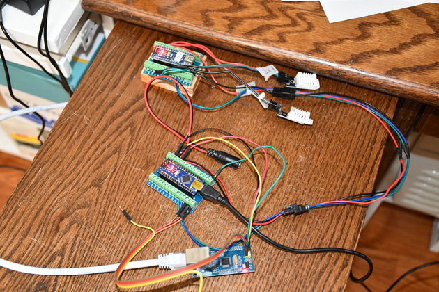
Test lash-up, with W5500 Ethernet Module.
The Nano (top) is running Environment Server with it's two DHT-22s, the Nano in the center is running the Gateway (NanoEth) program which converts ethernet packets to RS485 messages and back again, the W5500 Ethernet Module, at the bottom, is connecting the Env server to the local network.
|
|
Closer look at the W5500 Ethernet Module.
This is the module I choose for my gateway.
|
|
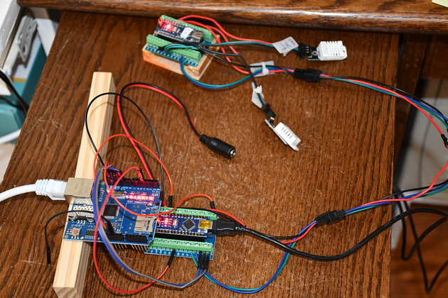
Test lash-up for Ethernet Shield 1.
|
|
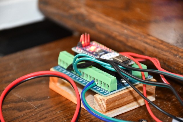
Closer look at the original Env server nano.
|
|
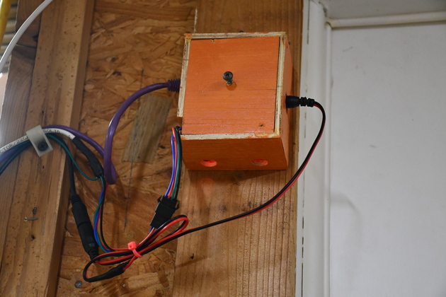
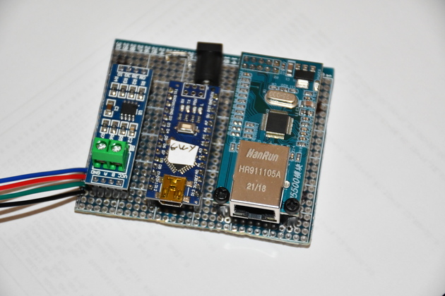
Closer look at completed Gwy board.
From left to right: Max485, Nano, and Ethernet Module.
WHen installed this is powered from the black 5.5 x 2.1 at the center top of the board.
|
Communications Definitions
Internet message packets will only contain ASCII characters.
The first 8 characters are a header, within the header, the 1st 4 characters are the packet's data length, the 2nd 4 chars are zeros for now.
| |
|
|
Useful ASCII Char Defns
|
| SOH | Start of Heading
|
| STX | Start of Text
|
| ETX | End of Text
|
| ENQ | Enquiry
|
| ETB | End of Transmission Block
|
| SYN | Synchronous Idle
|
| FS | File Separator
|
| GS | Group Separator
|
| RS | Record Separator
|
| US | Unit Separator
|
|
|
|
| Initial slave prefixes
|
| EN | Environment server
|
| DA | Dust Auto System
|
| AC | Shop Air Cond Thermostat
|
| DT | Data Terminal (part of Dust Auto)
|
|
|
Each RS-485 msg begins with '#', a 2 digit destination host nbr, a 2 digit source nbr, and an Instr (with optional arguments).
The Instr may be followed by '>' and arguments.
Each message ends with a NEWLINE ("\n").
Ethernet messages, from the network, will only have a prefix indicating the recipient, like "AC" for Air Conditioner Thermostat
|
| #0100ENV
| Message, from master, requesting slave #1 (ENV Server) responds with Temps and Hums
followed by NL.
|
| #0200SYN
| Master checking if slave 02 has a msg for network server?
|
| #0002NAK
| Slave 02 doesn't have a message for Inet server.
|
| #0002ACK>Lin1:4201%gobbldygook\n
| Slave 02 responds with a message for Lin1 port 4201
Send command gobbldygook to lin1 on port 4201
|
| #0002ACK>lin1/index.html%BarkingMad\n
| Slave 02 responds with a message for Lin1/php/shadNdx.html
Send command BarkingMad to lin1/php/shadNdx.html
|
| Instr:
| ACK Positive response to a previous Instr
NAK Negative response to a previouise Instr
|
| ENQ
| A request for service, followed by the ASCII request info
Data following ENQ is to be sent to the nmbrd slave who responds with
ACK or NAK.
|
| SYN Poll request for access
| Slave may respond with a message to a site on the network or just a NAK.
|
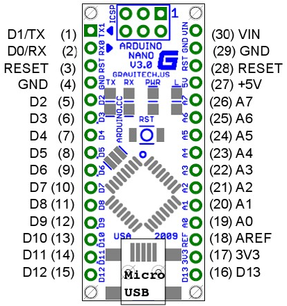
Nano Pinouts & Skiz
Nano Pin Definitions
|
|
|
|
| | | | |
|
| Arduino Nano Pin | Pin Name | Type | Function
| | 1 | D1/TX | I/O | Digital I/O Pin Serial TX
| | 2 | D0/RX | I/O | Digital I/O Pin Serial RX
| | 3 | RESET | Input | Reset (Active Low)
| | 4 | GND | Power | Supply Ground
| | 5 | D2 | I/O | Digital I/O Pin
| | 6 | D3 | I/O | Digital I/O Pin
| | 7 | D4 | I/O | Digital I/O Pin
| | 8 | D5 | I/O | Digital I/O Pin
| | 9 | D6 | I/O | Digital I/O Pin
| | 10 | D7 | I/O | Digital I/O Pin
| | 11 | D8 | I/O | Digital I/O Pin
| | 12 | D9 | I/O | Digital I/O Pin
| | 13 | D10 | I/O | Digital I/O Pin | SPI - SS
| | 14 | D11 | I/O | Digital I/O Pin | SPI - MOSI
| | 15 | D12 | I/O | Digital I/O Pin | SPI - MISO
| | 16 | D13 | I/O | Digital I/O Pin | SPI - SCK
| | 17 | 3V3 | Output | +3.3V Output (from FTDI)
| | 18 | AREF | Input | ADC reference
| | 19 | A0 | Input | Analog Input Channel 0
| | 20 | A1 | Input | Analog Input Channel 1
| | 21 | A2 | Input | Analog Input Channel 2
| | 22 | A3 | Input | Analog Input Channel 3
| | 23 | A4 | Input | Analog Input Channel 4
| | 24 | A5 | Input | Analog Input Channel 5
| | 25 | A6 | Input | Analog Input Channel 6
| | 26 | A7 | Input | Analog Input Channel 7
| | 27 | +5V | Output or Input
| +5V Output (From On-board Regulator) or +5V (Input from External Power Supply
| | 28 | RESET | Input | Reset ( Active Low)
| | 29 | GND | Power | Supply Ground
| | 30 | VIN | Power | Supply voltage
|
|
Nano ISCP Pins: 13,14,15,16
| | |
|

| Nano ICSP Pin Name | Type | Function | Description
|
| 1 | MISO | Input or Output | Master In Slave Out
|
| 2 | Vcc | Output | Supply Voltage
|
| 3 | SCK | Output | Clock from Master to Slave
|
| 4 | MOSI | Output or Input | Master Out Slave In
|
| 5 | RST | Input | Reset (Active Low)
|
| 6 | GND | Power | Supply Ground
|