For some time I have wanted to communicate with multiple devices (usually Arduino based) in my shop and house.
So far I have used RS232 for inter-device communications but, Arduinos have a limited number of ports so I'm restricted in the number of other hosts I can communicate with.
I would also like to be able to communicate with these devices from our networked computers.
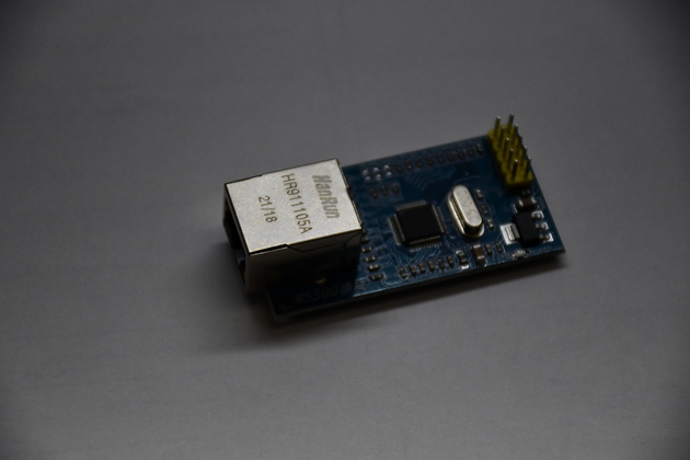
I did a lot of testing of Arduino ethernet modules and shields.  The W5500 seems
to work best for me.
RS-485:
Appears to be a good medium that has good distance and can address many devices.
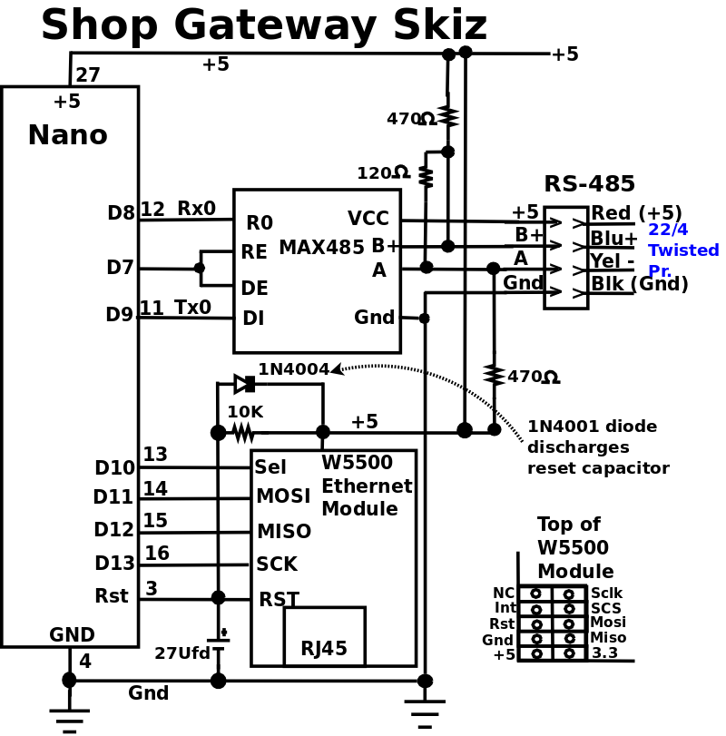
I'll use AltSerial to drive an RS-232 port on the Nano, then drive the RS-232 to a (MAX485), interface, to drive a shielded twisted pair 4 wire cable to remotes.
The RS-485 line will be run half-duplex, possibly with polling to allow any remote to initiate a request to other remotes or a network server.
One extra digital output pin (TXENA) will be required, from the Nano, in order to switch the MAX485 from receive to transmit.
GateWay:
A gateway between our home net (gigabit ethernet) and a new 485Net (RS-485 network) in the shop.
The gwy will run on a Nano with an Ethernet Module, use AltSoftSerial (initially), and a RS-485 adapter interface as the master of a 485Net in the shop.
TCP packets will only contain ascii characters, including an 8 char Info header, containing a 4 char packet length field and 4 extra bytes followed by an abbreviated slave name ("EN" environment, "AC" for mini-split thermostat, "DA" dust automation.
The gwy will use RS-485 for communicating with the devices (slaves) in the shop: Env, DustAuto, Shop AC thermostat (mini split AC), and Sprinkler System.
The RS-485 devices will be using ascii characters with a crunch (#) followed by a 2 digit destination host number and any arguments required by the slave.
RS-485 messages will contain a small, initial vector address which will enable gwy to determine the message's destination.
When a request arrives it will be forwarded to the correct server, wait for the response, and forward the response back to the sender on the ethernet network.
In this 1st version, during the processing of the request no other requests will be accepted, since most of these request take minimal time (ENV query takes < 3ms).
Requests and responses should be very quick, only tying up the gwy for a few MS.
NOTE:
Arduino has come out with a Nano Ethernet Shield and a Nano 485 Shield.
Now if you can stack the W5500 based Eth Shield, 485 Shield, and a Nano, that would solve the mounting/PCB problem, and should work great!
Only promlem is $$$$$, $26.40 for the Eth Shield, and $45.49 for the 485 Shield. I'll just have to wait for them to come down in price.
I did a lot of experimenting on different Arduino ethernet devices before I laid out the PCB.
Build:
I used a prototype PCB from Amazon.
.
I trimmed the PCB to size, soldered the in-line headers, used 18awg tinned copper buss wire for the ground and vcc, then wired the individual signals with 26AWG insulated wire.
I'm currently working on the message protocols.
RS-485 messages will all be in ASCII to keep things simple and avoid need for htonx and ntohx() functions.
MAX485 - RS-485 Interface Chip.
This interface board, uses a differential or balanced line to communicate to
other devices.
It may be used as a multi-drop line to communicate, in half duplex, over a
single twisted pair.
If you want full duplex, you would need two MAX485s and 2 twisted pairs.
The RE* and DE pins enable the respective Receive and Transmitt output pins.
Note Receive enable is Low enabled and DE is high enabled, so when using MAX485
in half duplex, tie them together and use as Transmitt Enable (TXENA).
Normally, all members of this half duplex network, keep the enable low so they
receive all traffic on the network.
When a device on the multi-drop cable wants to transmitt, it raise the TXENA,
transmitts, delays until data has been Txed, drop TXENA.

In order to allow two way communicaion, with a single pair, you must employ a
line turn-around protocol.
| Max485 Pins
|
| Pin Name | Use
|
| VCC | +5V
|
| A | Non-Inverting Receiver Input
Non-Inverting Driver Output
|
| B | Inverting Receiver Input
Inverting Driver Output
|
| Gnd | Gnd (0V)
|
| R0 | Receiver Out (RX pin)
|
| RE | Receiver Output (LOW-Enable)
|
| DE | Driver Output (HIGH-Enable)
|
| DI | Driver Input (TX pin)
|
02/08/22: Page Origin
| | |
|
|
|
| Click For Larger Pic
|
Testing
|
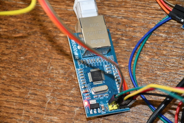
A closer look at a W5500 Ethernet Module.
|
|
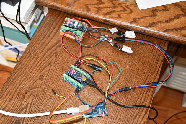
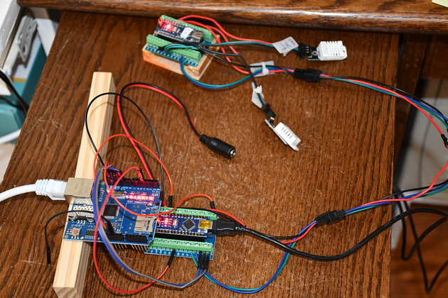
Test lash-up, with W5500 Ethernet Module.
The Nano (top) is running Environment Server with it's two DHT-22s, the Nano in the center is running the Gateway (NanoEth) program which converts ethernet packets to RS485 messages and back again, the W5500 Ethernet Module, at the bottom, is connecting the Env server to the local network.
|
|
Closer look at the W5500 Ethernet Module.
This is the module I choose for my gateway.
|
|
Test lash-up for Ethernet Shield 1.
|
|
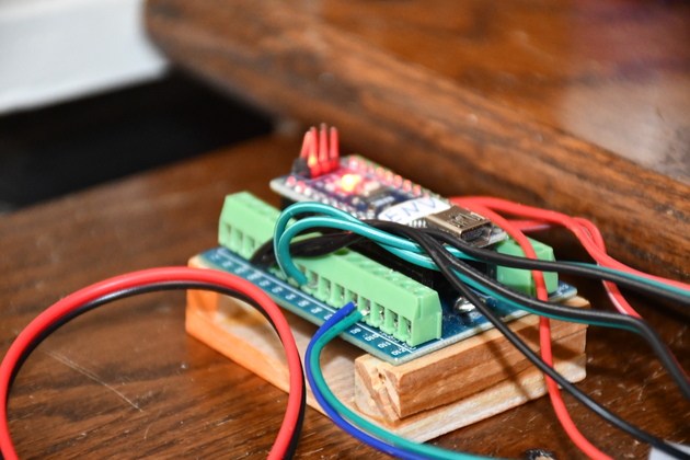
Closer look at the original Env server nano.
|
|
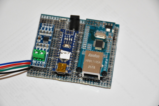
Closer look at completed Gwy board.
From left to right: Max485, Nano, and Ethernet Module.
When installed this is powered from a switching wall-wart connected to the black 5.5 x 2.1 barrel connector at the top center of the board.
|
Install
|
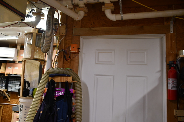
Door from shop to utility room.
Note the gateway installed in orange box high on the left door facing.
|
|
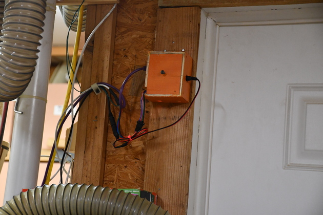
A little closer look at the installed gateway.
|
|
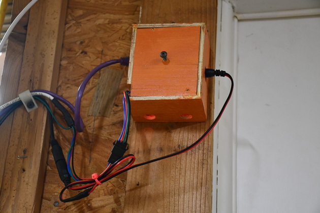
Close look at the gateway.
The holes on bottom (and a matching pair on top) are for convection cooling.
BTW, the screw in the center of the mount is a handle for removing the gateway base from the housing.
|
|
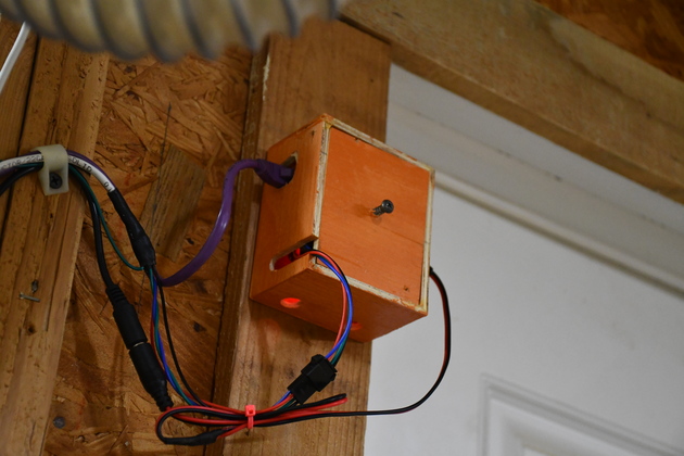
Left side, you can see the Cat-5 hole (purple cat-5 cable) and the slot for the RS-485 wires.
The purple cat-5 cable comes from the shop's 5 port gigabit switch (below).
|

|
The shop's 5 port gigabit switch.
The purple wire goes to the shop's gateway (a Nano).
|
