After some digging, I figured out a few things:
You have to use an Arduino DUE to change ESP8266's baud rate down to something Nano can handle.
You don't need to change it's internal software, unles you just want to.
You should use NeoSoftwareSerial (or something like it) to drive the ESP8266, freeing up the normal serial line to talke to the IDE.
The normal AT instructions set that comes with the ESP8266 should do most of what you want.
You can probably look at the WiFi & NTP libraries to see the ascii commands you need to do whatever you want.
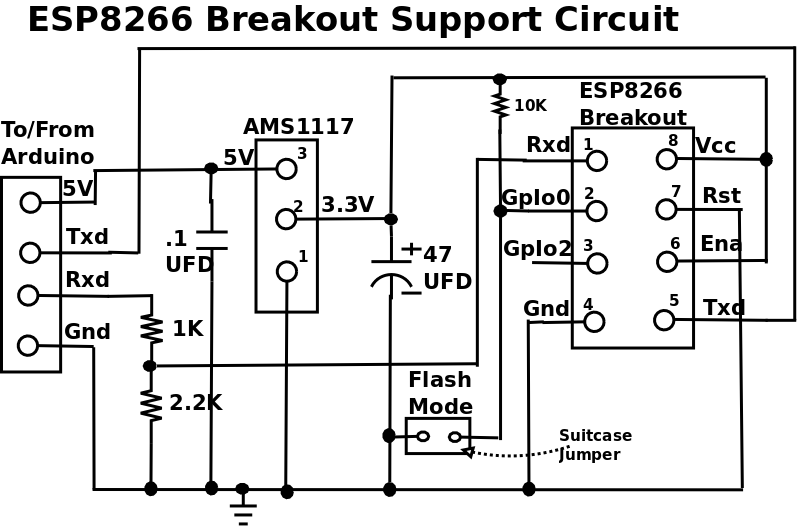
The ESP-01 is a microprocessor system, built around the ESP8266 chip, with built-in WiFi, which runs on 3.3V.
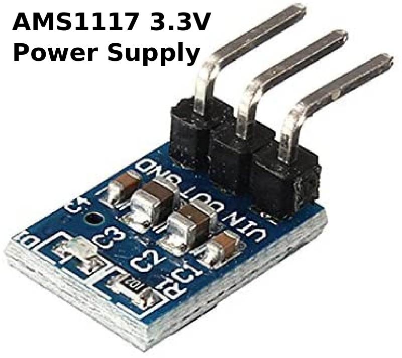
The 3.3v regulator in Arduino Uno and Nano isn't beefy enough to support the ESP-01's current requirements, hence an external 3.3V power supply (like the AMS1117) is needed.
The Arduino runs on 5V so it will need a level shifter in order to communicate with the ESP-01.
ESP8266 module comes pre-programmed with an AT command set firmware, meaning, you can simply hook this up to your Arduino device and get about as much WiFi-ability as a WiFi Shield offers.
This module has a powerful on-board processing and storage capability that allows it to be integrated with the sensors and other application through its GPIOs
The ESP8266 wireless chip seems to be very flexible wifi.
I'll soom be giving it a try, for both TCP and UDP (fetch NTP).
06/04/22: Page Origin
ESP-01
|
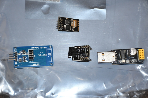
ESP-01 (top) and 3 support boards.
Bottom row ESP-01 Adapter (left) , Breakout (middle), USB serial (right).
|
|
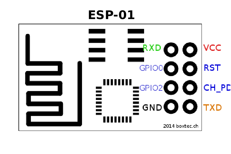
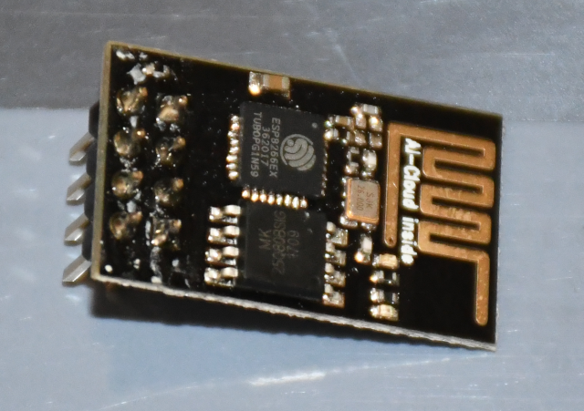
The ESP-01 with it's ESP8266 chip.
Note the antenna on the right end.
Requires 3.3V power.
|
|
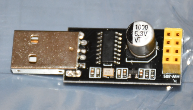
ESP-01 USB.
This guy can be plugged directly into a computer's USB-A and allows serial ASCII characters to cotrol it, via 'AT' commnad set.
|
|
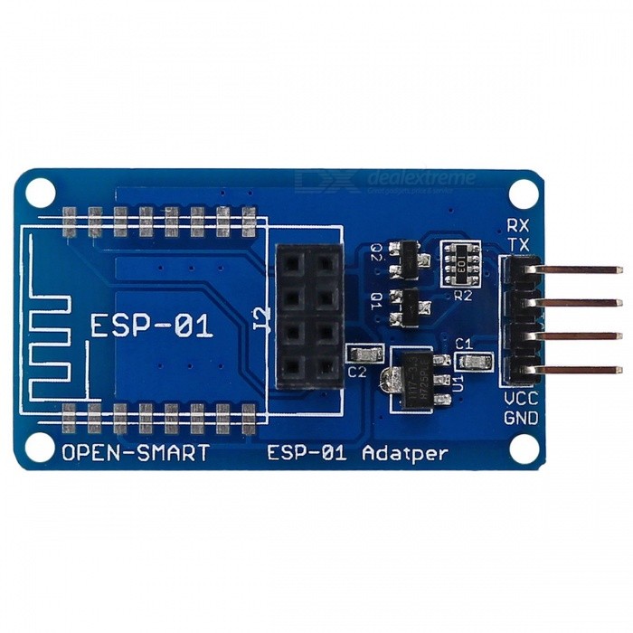
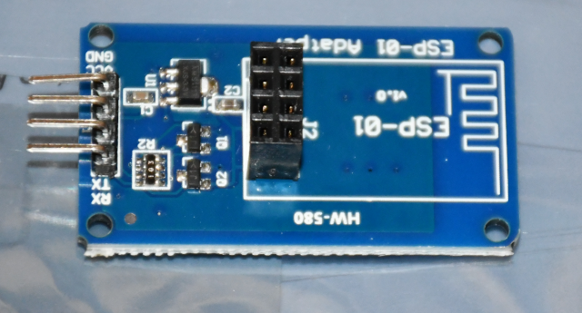
ESP-01 adapter.
This board contains all the support circuits required by the ESP-01.
|
|
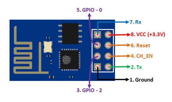
VCC shall be connected to the 3.3V power supply.
|
|
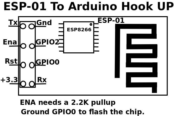
GPIO0 and GPIO2 are general purpose digital ports. GPIO0 also controls the module mode (programming or normal operation). In our case (normal operation), it shall be connected to 3.3V (high). GPIO2 is not used in this example.
|
|
Rx: Goes to Arduino pin0 (But needs a voltage adjusting).
|
|
CH_PD: Chip enable. Keep it on high (3.3V) for normal operation.
|
|
RST: Reset. Keep it on high (3.3V) for normal operation. Put it on 0V to reset the chip.
|
|
GND is ground.
|
|
Tx: Goes to Arduino pin1.
|
06/02/22: Page Origin
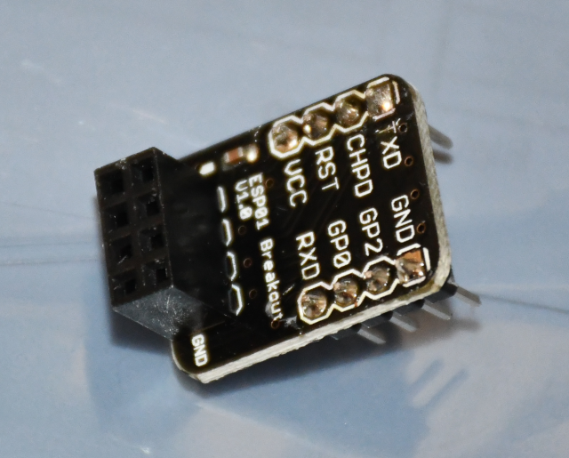
ESPBreakout
ESP Breakout
In addition to allowing connection to an Arduino, may also be ued to program the microprocessor at the heart of the ESP-01
Programming:
Now before hitting upload, take GPIO-0 to ground.
And RST to ground afterwards, remove RST after half a second (the blue LED flashes for some millisecond).
Hit upload, the blue flashes once and then blinks till it gets uploaded.
Now you are all done.
|
|
|
Connections for programming
(Find code in attachments)
|
| ESP8266 | Arduino:
|
| GND | GND
|
| GPIO-2 | Not connected (open)
|
| GPIO-0 | GND
|
| RXD | RX
|
| TXD | TX
|
| CHPD | 3.3V
|
| RST | Not connected (open) *(Read Instructions)
|
| VCC | 3.3V
|
After programming, remove the serial Arduino cable and plug it again and take out GPIO-0 from GND and just interchange the connection of RX and TX that is RX connect to TX and TX connect to RX.
|
|
|
Connections after programming
|
| ESP8266 | Arduino:
|
| GND | GND
|
| GPIO-2 | Not connected (open)
|
| GPIO-0 | Not connected (open)
|
| RXD | TX
|
| TXD | RX
|
| CHPD | 3.3V
|
| RST | Not connected (open)
|
| VCC | 3.3V
|
ESPAdapter
ESP Adapter
Contains all interfaceing components to connect the ESP-01 to an Arduino, but does not allow programming it's micropresossor.