Arduino Nano and Uno have problems with high serial baudrates, depending on what other libraries, etc. are currently being used.
When using a Nano/Uno with an ESP-01 (ESP8266) you must supply the ESP-01 with 3.3 volts, Nano and Uno's 3.3 V regulator is a little wimpy for this.
Also, since the Nano and Uno use 5V logic on their digital output pins you should use a level shifter to protect at least the ESP8266's Rx input.
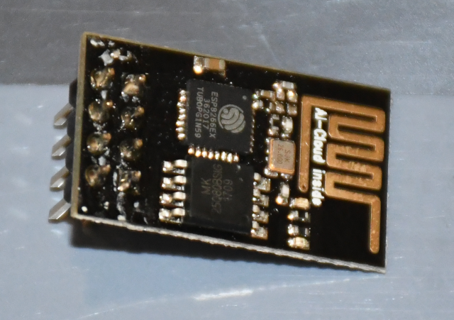
In order to use a new ESP-01 (ESP8266 WiFI) with Arduino Uno or Nano (like in a clock), you must first change it's baud rate.
The ESP-01 comes with 115200 baud as it's default, however the Uno and Nano can't talk that fast.
So you must use a faster Arduino board (I used a DUE) which can talk at 115200 baud.
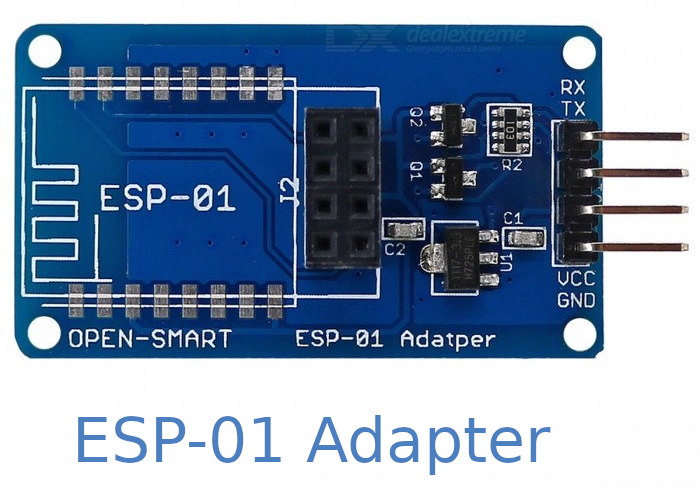
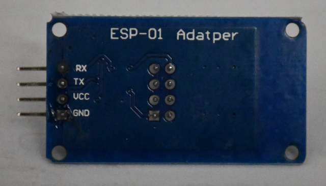
I connect an ESP-01 Adapter board to the due, using it's UART1: pins: 18 Tx to the Adapter's Rx and 19 Rx to the Adapter's Tx pins.
Tie the Due's ground to the Adapter's ground and the Adapter's vcc pin to the Due's 5V pin.
Note were using 5V to the Adapter, it has a 3.3 volt regulator for the ESP-01.
The Adapter also has level shifters so you can tie the Due's Rx Tx to it's Tx Rx without worrying about killing the ESP-01's 3.3 volt logic.
Once the ESP-01 (ESP8266) is connected via the Adapter board, you can run the passthrough program to configure the ESP8266 to talk to Nanos and Unos.
The AT commands needed to lower the ESP8266's baudrate so Nanos and Unos can talk to it.
Note you must send a \r\n (carraige return and newline) after each line.
	AT                             # ESP should respond "OK"
	AT+RST                         # Resets ESP
	AT+UART_DEF=9600,8,1,0,0       # Sets ESP UART: 9600,N,8,1,no flow ctl
# Now change terminal emulator baud rate to 9600, and you should be "cooking with gas".
After initializing the ESP-01 (reducing the baud rate) you should be able to send "AT" commands to it to make it talk to the network vi a WiFi link.
|
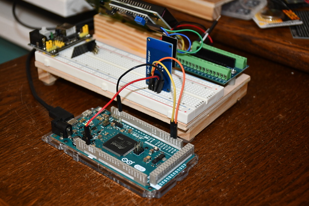
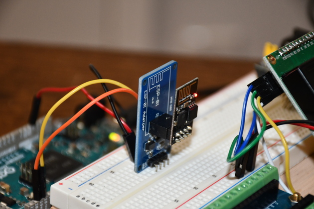
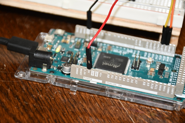
My initializing setup, note the Due with power (5V), ground, Serial1 Tx, and Serial1 Rx tied to the ESP-01 Adapter plugged into the breadboard.
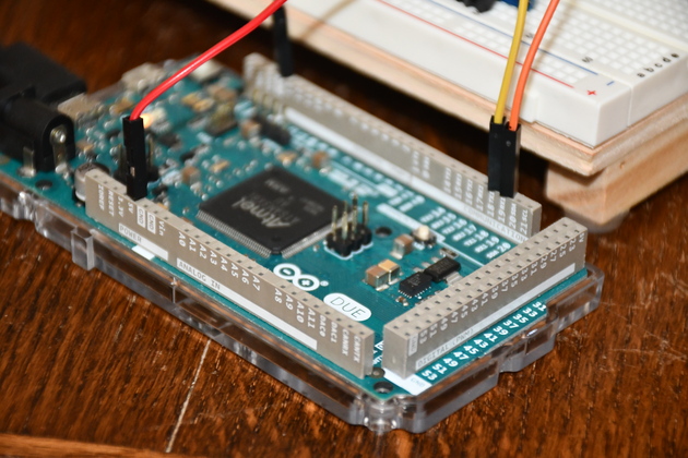
Note micro USB plugged into the Due's "Programming" port.
|
|
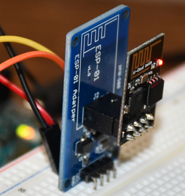
You can see the ESP-01 plugged into the Adapter and the Adapter board plugged into the breadboard.
|
|
Closer look at the DUE.
Only 4 wires connected.
|
|
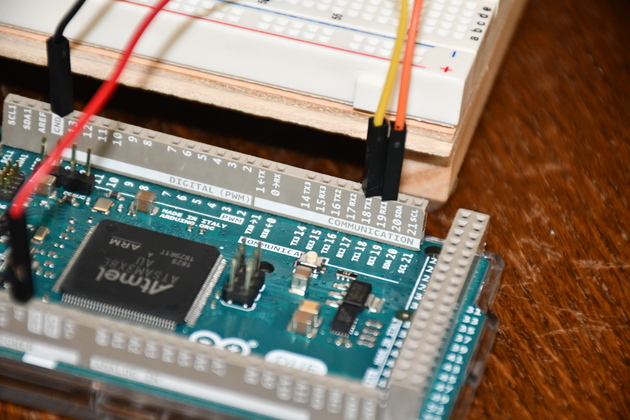
Closer look at the yellow Tx jumper and the orange Rx jumper.
|
|
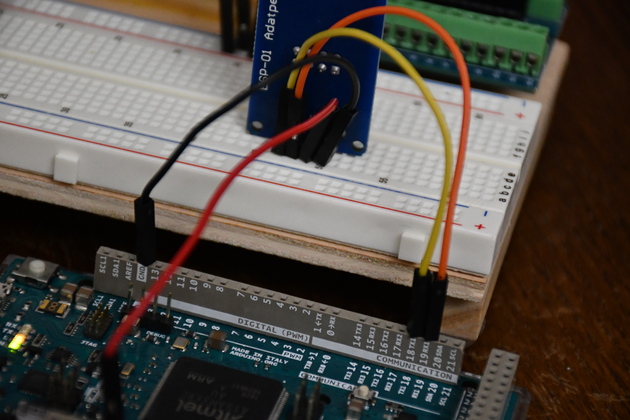
Better look at the jumpers tied to the Adapter board.
Note yellow jumper is from Due's Tx to Adapter's Rx and orange jumper from Due's Rx to Adapter's Tx.
We don't have to use any lelel shifters, the Adapter does it for us.
|
|
Here you can see the red vcc jumper from the Due's 5V.
As I mentioned earlier, the Adpater regulates the 5V down to 3.3 for the ESP8266.
|