After several steps of preparation, the ESP8266 can finally be programmed. Fortunately, this step has been made fairly simple by using, what is a familiar platform for many, the Adruino IDE.
Table of contents
| Introduction | |
| To get started you will need | |
| ESP-01 Arduino IDE examples | |
| Using the ESP-01’s onboard LED (GPIO1) as output | |
| Using the ESP-01’s GPIO0 and GPIO2 as output | |
This post will show how to upload a few variations of the basic Blink sketch to an ESP-01 together with the wiring of LEDs.
Before being able to connect the ESP8266 to any programming software, the basic knowledge of wiring the chip into ‘flash’ mode (vs. boot mode) will be required. Refer to connecting the ESP-01 module to a breadboard and FTDI programmer for more information. In addition to this, the ESP8266 core needs to be added to the Arduino IDE and the appropriate FTDI programmer drivers need to be installed.
These were the parts that were used. Most are available from BangGood and Amazon.com . Some direct links to some of the parts are supplied lower down.
| Mini-B USB cable | |
| Breadboard and solderless breadboard jumper cable set | |
| Larger than ~185 Ohm resistor | |
| 3 mm or 5mm LED |
Apart from and ESP-01 or ESP-01S and the requirements for wiring this board into ‘flash’ mode, you will also need a device with a recent version of the Arduino IDE. Also see installing the Arduino IDE on a Raspberry Pi 3 for more information.

The ESP-01 has two, easy-to-use, GPIO pins (GPIO0 and GPIO2) and a blue on-board LED (GPIO1). Examples for using all three these pins will be given.
Before sketches can be uploaded, the ESP-01 needs to be booted in ‘programming’ mode. When using the breadboard and FTDI programmer method , the SPDT slide switch needs to connect GPIO0 to GND before pressing the reset switch.
After a sketch is uploaded, the ESP-01 should be wired back to ‘normal’ operating more and rebooted i.e. the SPDT slide switch should not connect GPIO0 to GND before pressing the rest switch.
To start off, the sketch below will make the ESP-01’s blue onboard LED blink at 1-second intervals. Because GPIO1 on the ESP-01 also doubles as the Tx pin, the serial monitor cannot be accessed at the same time. Without having to connect anything to the ESP-01, upload the following Blink sketch:
/*
  ESP8266 Blink
  Turns on an LED on for one second, then off for one second, repeatedly.

  Blink the blue LED on the ESP-01 (and the ESP-12) module
  ESP-01s have an on-board LED you can control.
  On the ESP-01 and ESP-12, it is attached to GPIO1.
  (which is also the TXD pin; so Serial.print() cannot be used at the same time)
*/

#define LED 1   //  define connection of LED, in this case GPIO1
// the setup function runs once when you press reset or power the board
void setup() {
  pinMode(LED, OUTPUT);     // initialize the LED pin as an output
}

// the loop function runs over and over again forever
void loop() {
  digitalWrite(LED, LOW);   // turn the LED ON
  delay(1000);              // wait for a second
  digitalWrite(LED, HIGH);  // turn the LED OFF
  delay(1000);              // wait for one second
}
Note that on the ESP-01’s, the onboard LED is turned on by a LOW voltage and off by a HIGH voltage.
The sketch below will make an external LED connected to the ESP-01’s
GPIO0 blink at 1-second intervals. To use GPIO2 instead, simply change
#define LED 0
to
#define LED
in the variable section.
/*
  ESP8266 Blink
  Turns on an LED on for one second, then off for one second, repeatedly.
*/

#define LED 0   //  define connection of LED, in this case GPIO0
// the setup function runs once when you press reset or power the board
void setup() {
  pinMode(LED, OUTPUT);     // initialize the LED pin as an output
}

// the loop function runs over and over again forever
void loop() {
  digitalWrite(LED, LOW);   // turn the LED off
  delay(1000);              // wait for a second
  digitalWrite(LED, HIGH);  // turn the LED on
  delay(1000);              // wait for a second
}
Out of the box, LEDs will have a long leg (anode) and a short leg (cathode). The specifications (forward Voltage or V f @ a specific current or I f ) of LEDs (usually size and colour dependent) will be available from the manufacturer/datasheet.
Each pin of the ESP8266 supplies 3.3V DC and 12mA of current. It is generally not recommended to draw more than 7mA per pin, so according to Ohm’s law, a current limiting resistor of ~185 Ohm or more is generally safe to use. Resistors can be connected directly to a breadboard. One leg is connected to the cathode of the LED and the other leg is connected to the ground (GND) pin of the ESP-01. It doesn’t matter which side of the resistor is used where.
LEDs can be connected directly to a breadboard. Because the input status of GPIO0 and GPIO2 is used during the boot process to determine the mode which the ESP8266 needs to enter, their default status should not be altered. Instead of connecting the LED between the GPIO pin and GND, it needs to be connected between Vcc and GPIO0/GPIO2 [and the resistor needs to be connected from the cathode (short leg) to GPIO0/GPIO2].
This will mean that GPIO0/GPIO2 will be LOW (i.e. on) during bootup until its value is set to HIGH (i.e. off). To keep the LED off until the loop section has been reached, the following command can be added to the sketch’s setup section (also see the 4 basic sections of an Arduino sketch for more information):
// the setup function runs once when you press reset or power the board void setup() {
  pinMode(LED, OUTPUT); // initialize the LED pin as an output
  digitalWrite(LED, HIGH); // turn the LED off during setup
}
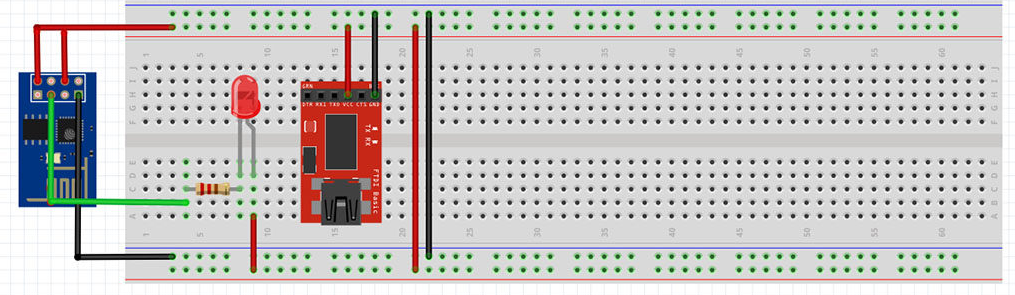
After the sketch was uploaded, the LED needs to be connected as follows:

To connect a LED to GPIO2, the green wire needs to be moved to GPIO2 instead. Both GPIO0 and GPIO2 can be used as digital outputs at the same time.