| 
| 
| 
|
|
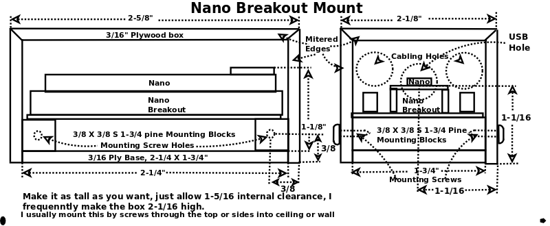
Nano Mount
| |||
|
|
|
|
|
|
Nano Mount
| |||
| Dust Collector Automation | Dust Detector | Environment Server | Dust Detector Mount |
| Dust Auto | Mini Cauls | Nano 485 Gateway |
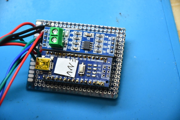
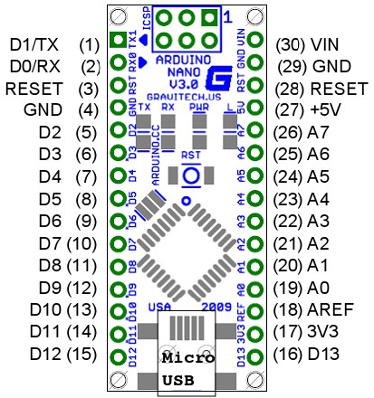
I have been using a number of Arduino Nanos in shop projects and mounted on Nano Breakout boards.
Most of the time I build a small box to house the Nano
and it's
breakout board,
and I've built enough of them now, I decided it needed it's own page.
There are two in the DustCollection Automation project.
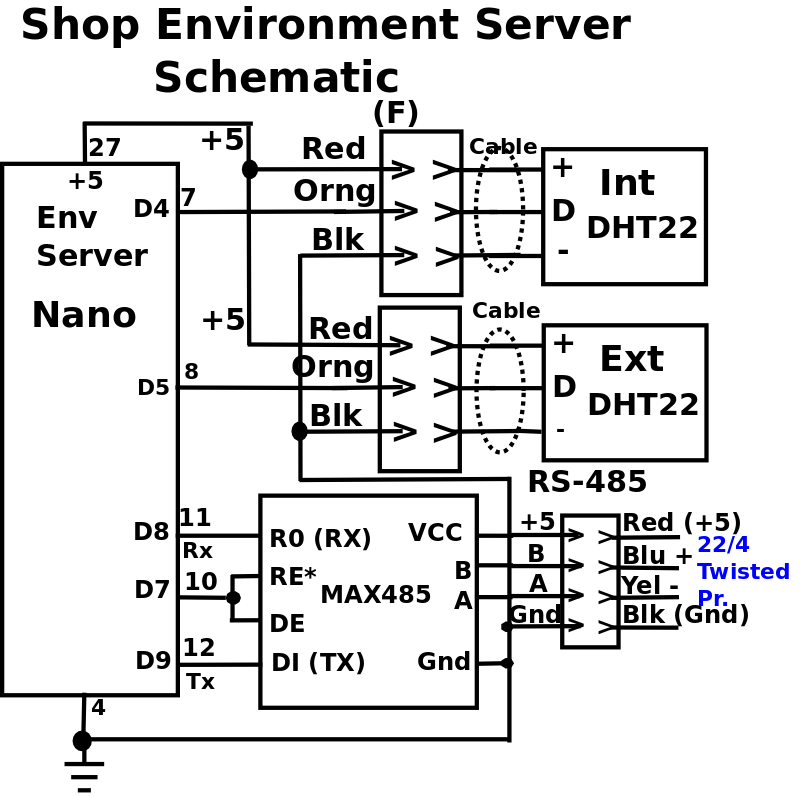
One in the Shop Environment project.
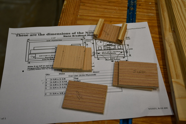
I build these out of 3/16" plywood (Underlayment), with mitered corners.
Miter all edges except the bottom edge.
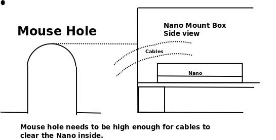
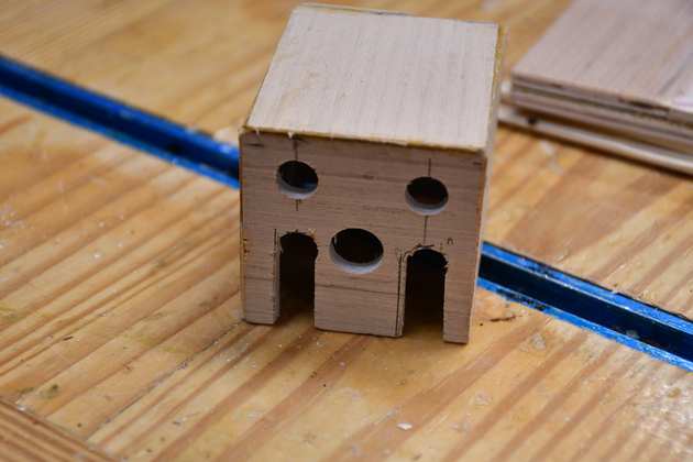
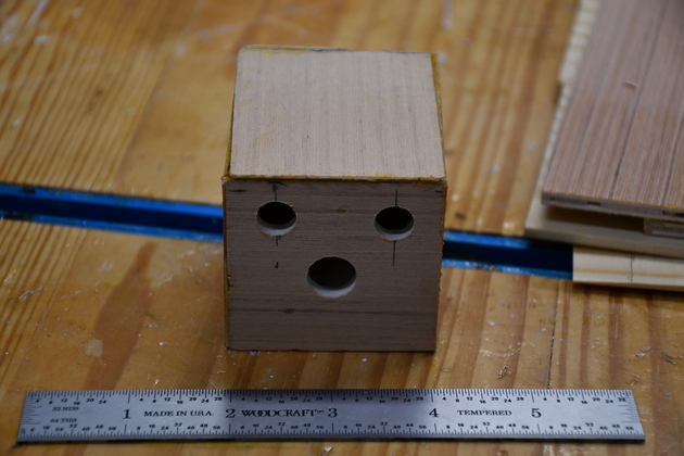
I drill holes in one end for cables and a 1/2" hole for the mini-USB in case you need to change the sketch.
End holes also allow a little convection air to move through the box, reduces heating.
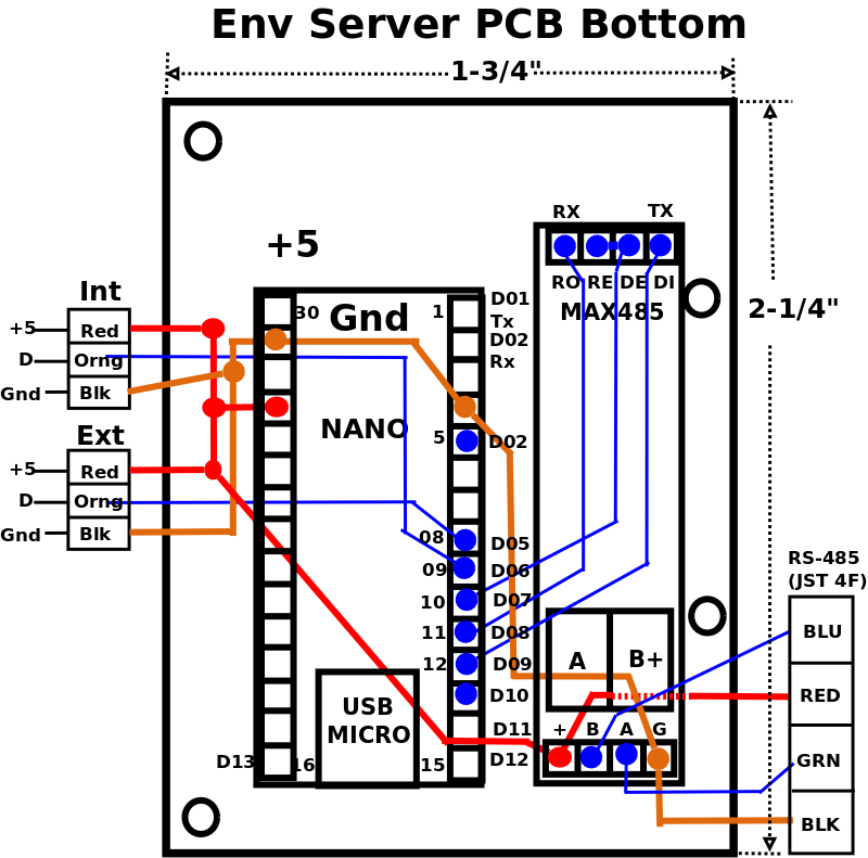
I originally used a Nano breakout with screw terminals, but when I converted to RS-485 (added a MAX485), I had to make a PCB the same size as the Nano breakout.
|
Click For Larger Pic |
|
|
|
| |||||||||||||||||||||||||||
|
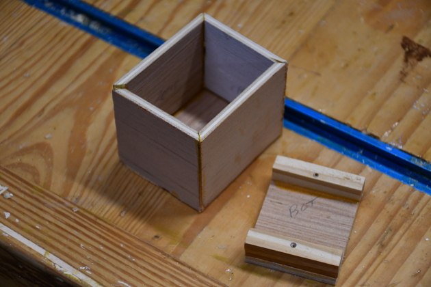
Parts cut out, ready to miter. The bottom doesn't need mitering and already has the support blocks glued on. |
|
Pieces mitered, I use a 45° router bit to miter these pieces. Note that the ends and sides have one unmitered edge, thats the bottom edge. Note, on the bottom piece (on right), I have already glued the two mounting blocks. |
|
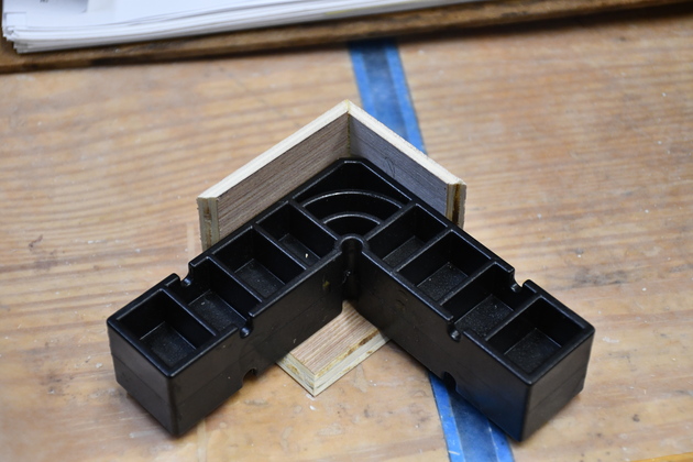
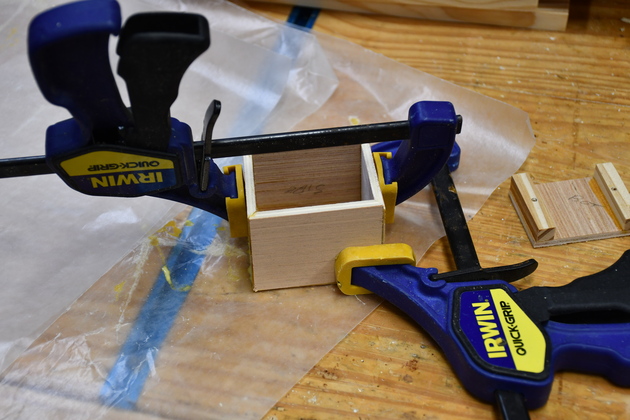
Starting to glue, here I'm gluing one side and one end to the top. The mini-Clampit makes everything is square. |
|
Different angle, I'm gluing one side to an end and the top (now on the bottom). The mini-ClampIt keeps every thing square till the glue sets. Normally, when gluing a larger mitered box together, I'd use a set of my Clamping Cauls. |
|
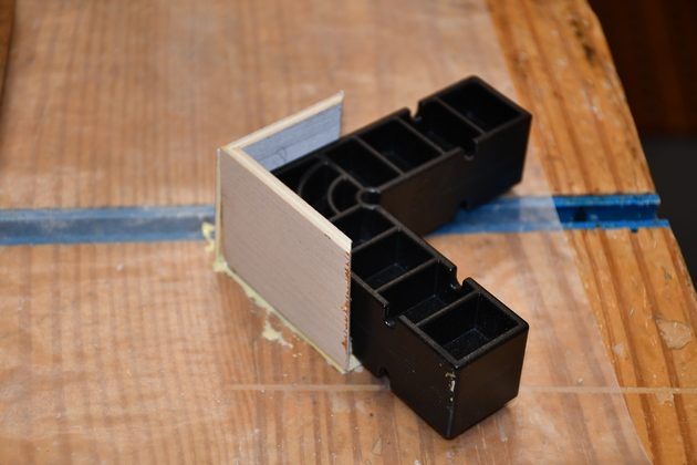
Here I'm gluing the other side and end to each other. Again, the mini-ClampIt holds everything square. |
|
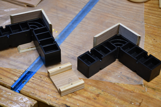
Side by side, now all that remains, after the glue sets, is to glue the two pieces on the right to the 3 on the left, then drill the holes for cables and mounting screws. |
|
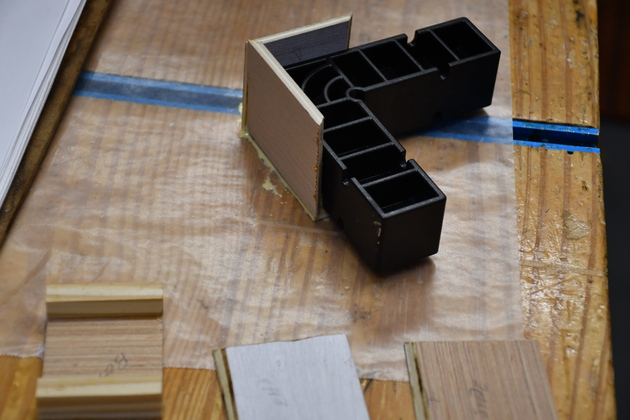
Gluing the last end/side pair to the other end/side, and top. You can see the bottom off to the right. |
|
|
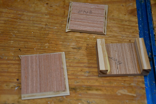
After final glue. The cover and it's bottom. |
|
|
|
|
Two air holes on the back side. |
|
|
Mouse Holes cut. |
|
|
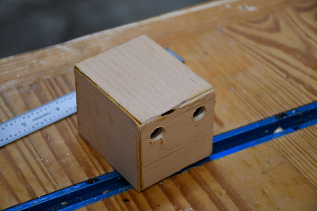
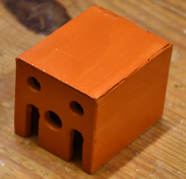
Painted an outstanding color. |

|
|