11/23/20: Page Origin
During the COVID_19 pandemic, in late 2020, I had been looking at the smaller PowerMatic lathes for some time when PowerMatic ran a 10% off sale (Nov 2020) on the PM2014, so I pounced.
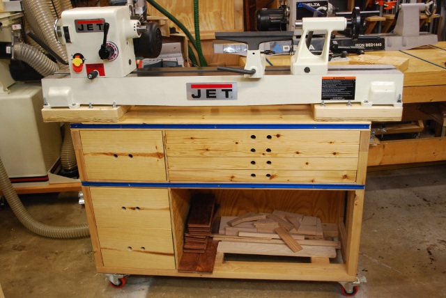
My Jet JWL1442VS was a great lathe but just too big for my shop, I just don't need a 40" lathe.
The old Lathe Bench (built for a Delta 1440) was 48" wide but the Jet stuck out over each end 5".
The old lathebench had a flat front, no knobs drawer pulls etc., because of the dust collector extension (slid back and forth on the front tee tracks) I originally used when turning a bowl.
Two other items:
Spindle
JWL1442VS has a 1" 8TPI drive spindle, PM2014 has a 1-1/4" 8TPI drive spindle, so I ordered an 1" to 1-1/4" adapter
for faceplates and such and new inserts for my OneWay chucks.
Outboard Turning:
I ordered the 13" bed extension for those times when I did need something longer or bowl turning.
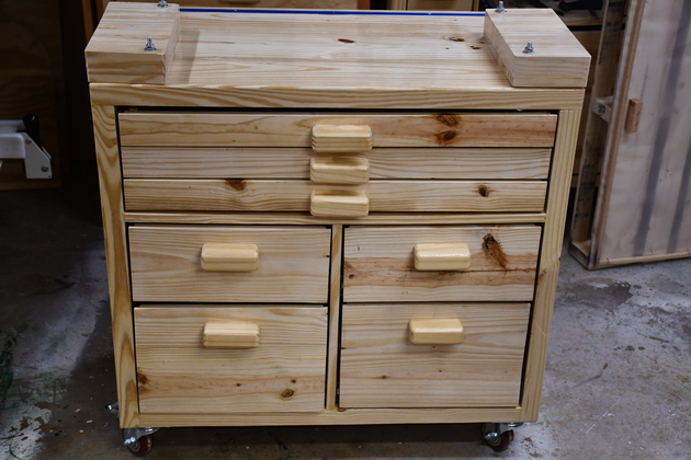
After ordering the PM2014, I started thinking about a new bench (LatheBench2) for it.
LatheBench2 doesn't need a flat front, If I turn a bowl, it will be at the end rather than the middle of the bed.
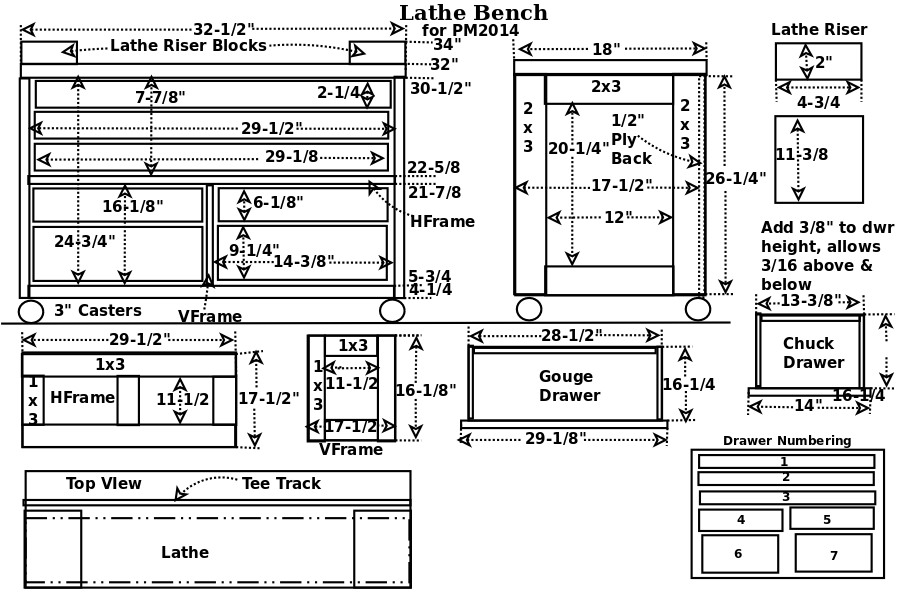
This bench isn't as wide or high as my original lathe bench since the PM2014 is taller (17-1/2") than the JWL1442VS, also I have some restraints due to shelves in the shop.
I put a tee track on the back of the bench top, for an arm light and dust hood.
I didn't put tee tracks on the front (for dust collector), since I won't be doing any outboard turning in the middle, and the large dust funnel on the back works OK.
I measured the spindle height of the JWL1442VS at 48" from the floor, the PM2014 base bottom to spindle is 14" so the new bench risers should be 34" high, making the PM2014's spindle 48" from the floor.
The LB2 (LatheBench2) would have 3 slightly wider gouge drawers and 4 drawers for chucks, keys, and other accessories.
The old Lathe Bench had a large empty space below the gouge drawers, LB2 would not.
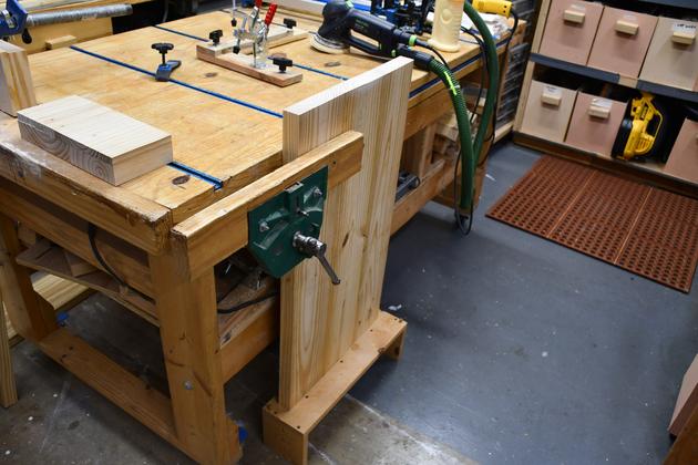
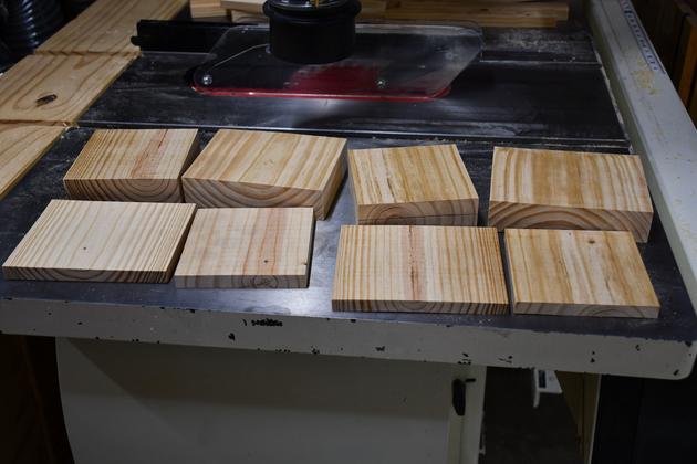
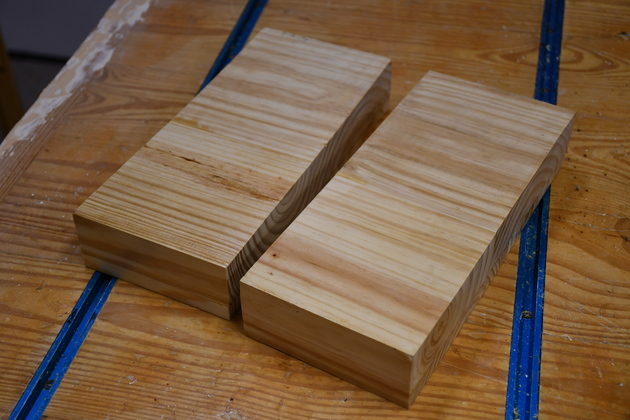
I'll need to make some 2" thick X 4-3/4 X 11-3/8" end blocks for the PM2014, I like to put gouges on the table top under the lathe while I'm turning so I have to raise it (note the blocks under the JWL1442VS in the original lathe bench pic above).
In order to get exactly 2" I'll resaw then plane a piece of SYP to 1/2" then laminate it to a 1-1/2& thick piece.
I usually use double locking 3" casters and full extension slides on these machine benches.
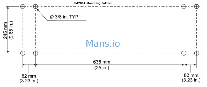
I'll only use four 5/16-18 x 4-1/2" long hex bolts to mount the bed to the bench, the manual says thats OK.
12/13/20
Design the project (I use dia)
Construction Steps:
Prepare the lumber (based on the
Cut List):
Saw all the pieces to length
Rip to width
Resaw and plane to the required thickness
Build the sub structures:
Edge join the top
Glue Frame ends
Glue HFrames and VFrames
Sand the sub-stuctures
Assemble the substructures into the frame.
Glue the ends to the top
Glue the internal HFrame to the ends
Glue the internal VFrame to the HFrame
Glue on the bottom stringers and the back
Once the frame is assembled, round the corners, sand, and paint
Last, make the drawers using the same steps above.
12/07/20
I've noticed that 2x8x8s are starting to come down after Trump's tariff trippled the price.
2x10x8' is cheaper than 2x8x8'.
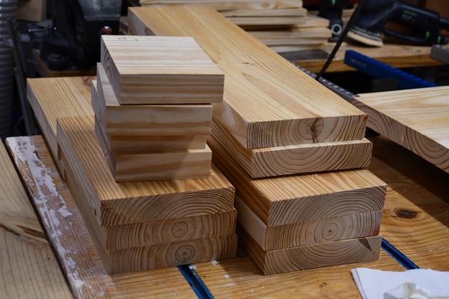
Lumber Prep
|
2x8s cut to length.
I'll rip and resaw until I have the pieces I need (1x3, 2x6, 2x5).
|
|
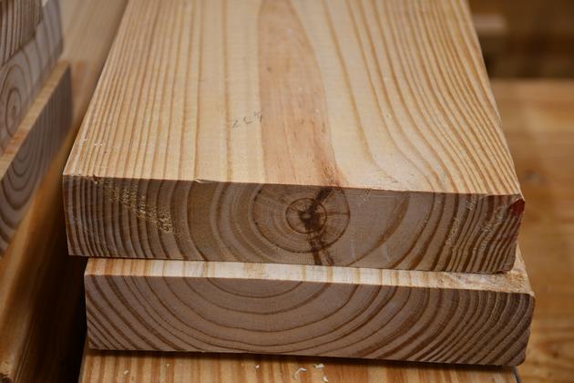
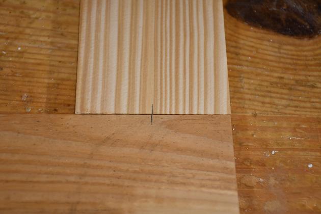
Note I ripped about 1/8" off the left side of al 2x8s, you can see the difference in the pic: ripped left and factory milled corners on right.
I'll start ripping narrower pieces from the left side so all pieces I end up with have nice square corners (not factory milled).
|
|
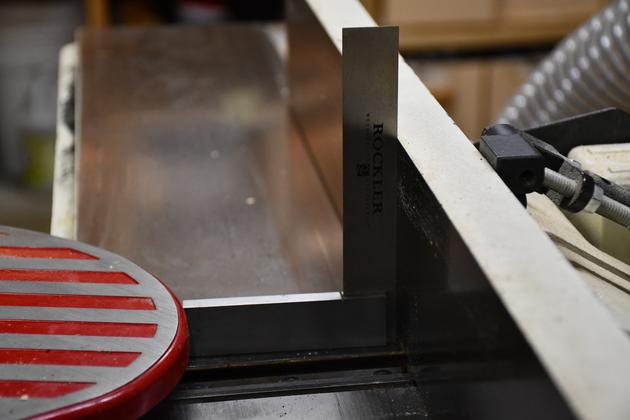
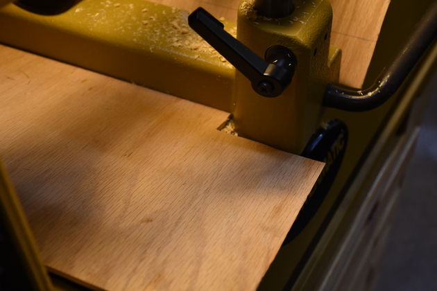
Setting up my jointer before edge jointing top pieces.
|
|
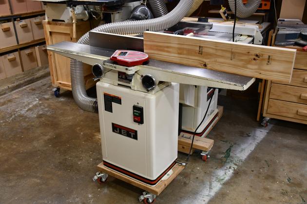
Edge jointing top piece.
I ripped the top pieces 1/8" wider, each pass on the jointer takes off 1/32" and they are usually ready to join after 2 passes across the jointer.
|
|
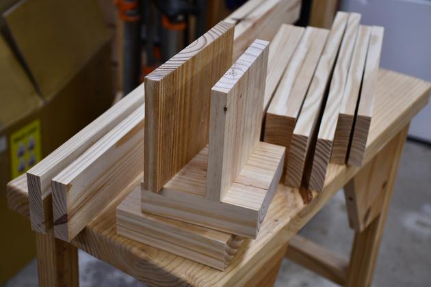
Vframe, Hframe, and riser block pieces resawn and planed.
|
Build Substructures
|
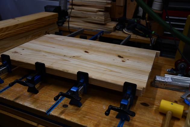
Top in the glue clamps.
There are 6 #20 biscuits in each joint.
|
|
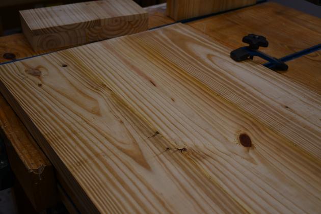
Top before sanding.
|
|
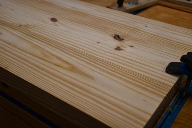
Top after rough sanding.
|
|
Sanding edges of bench top.
Note the single trestle bench raising the top's edge above the workbench top.
|
|
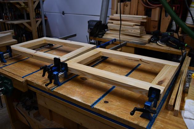
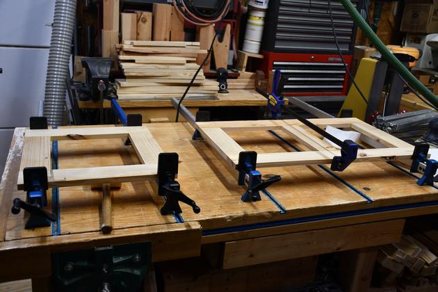
Frame ends in the glue clamps.
|
|
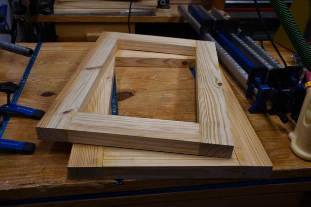
Frame ends, ready to sand.
|
|
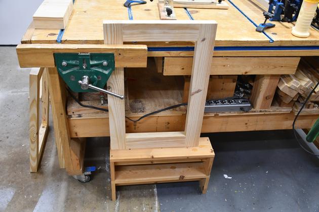
Sanding the top and bottom edges of the frame ends.
Note the stacked trestle benches raising the frame end top edge above the workbench top.
One of the next things to do is rout a rabbet for the inset 1/2" plywood panel.
|
|
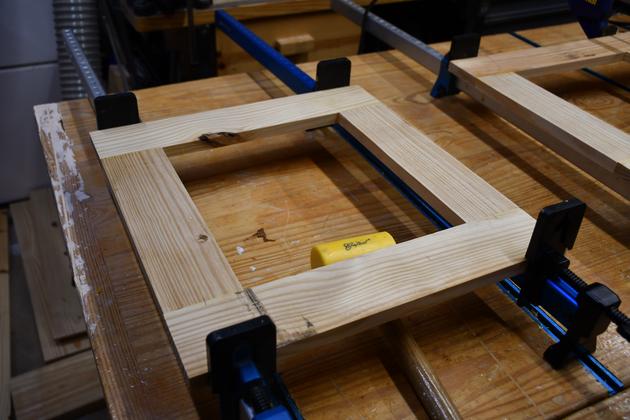
Marking biscuit position in joints of the HFrame.
|
|
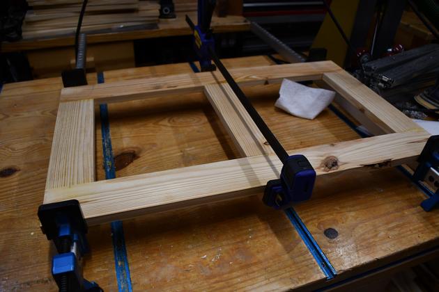
Vframe and Hframe in the glue clamps.
BTW, the dark yellow thing sticking up on the right back corner of the workbench is the PM2014 bed extension.
|
|
Closer look at the Vframe being glued.
|
|
Closer look at the HFrame being glued.
|
|
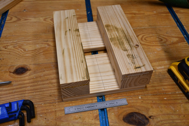
Lathe riser block pieces.
In order to make a 2" thick lathe riser block, I have to laminate 1-1/2" thick pieces to 1/2" pieces, and to make it 11-3/8" wide I need to edge joint two pieces, one 6-3/8" to a 5" wide piece.
In back are the 2" thick pieces, in front are the resawn 1/2" pieces.
I'll edge join the 1-1/2" pieces then laminate the 1/2" pieces with a 1-3/8" overlap in the center.
|
|
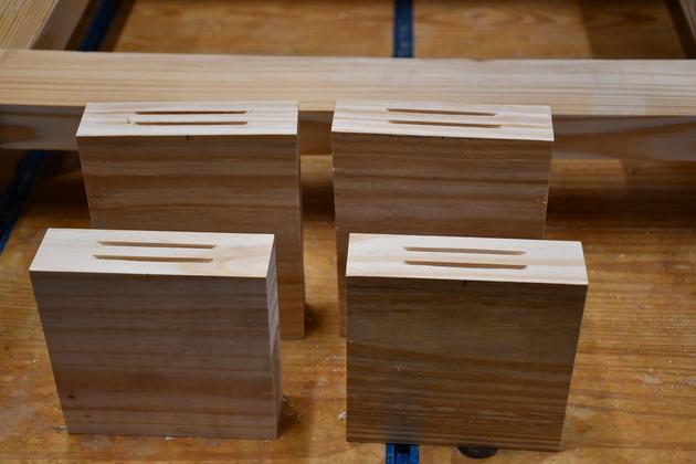
Slots cut into the 1-1/2" thick pieces of the lathe riser blocks.
|
|
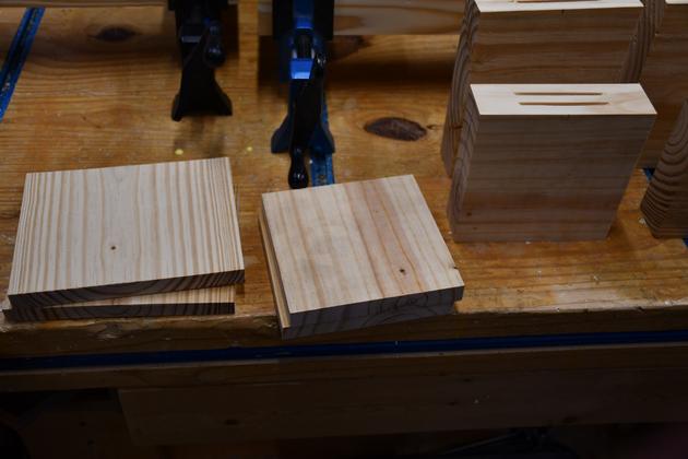
The 1/2" thick pieces of the lathe riser blocks.
|
|
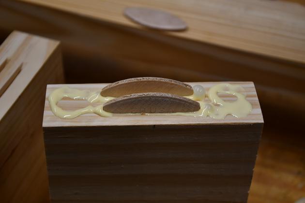
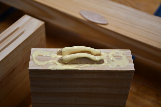
Glue and biscuits on the thicker lathe riser blocks.
|
|
Glue on top of the biscuits.
Note the glue bead should be in the center of the biscuit so it will run down both sides.
|
|
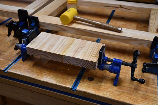
Edge joining two thick pieces of a lathe riser block.
Note the 6-3/8" piece is on the left, when these are laminated to the 1/2" pieces, the wider 1/2" thick piece will be on the right so the joints are staggered.
|
|
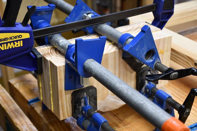
Both lathe riser blocks being laminated.
These 3/4" pipe clamps can each apply about 500# of pressure.
|
Assemble Frame
|
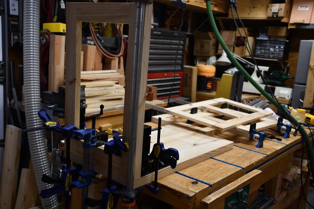
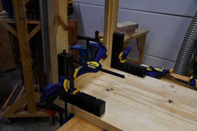
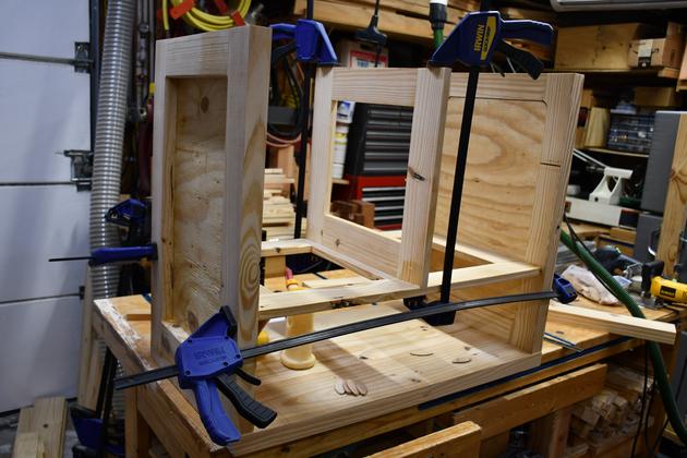
Gluing the right hand side to the top.
I consider the top as the mechanical base of the cabinet, I assemble cabinets upside down.
|
|
Closer look, note the ClampIts keeping everhthing square.
|
|
HFrame being glued to right end with ClampIts.
|
|
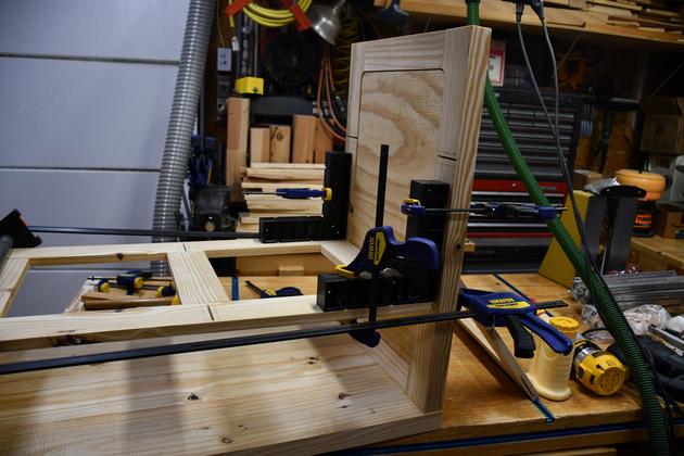
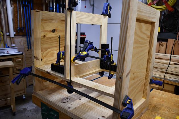
Gluing left end piece and HFrame.
Note inset plywood panels have also been glued into end pieces, this has to be done before I can glue in the HFrame.
|
|
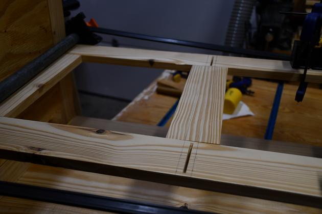
Note biscuit slots in HFrame for VFrame's top.
A little more on gluing biscuits.
|
|
Gluing the VFrame to the HFrame.
|
|
Note the ClampIts making sure its square.
|
|
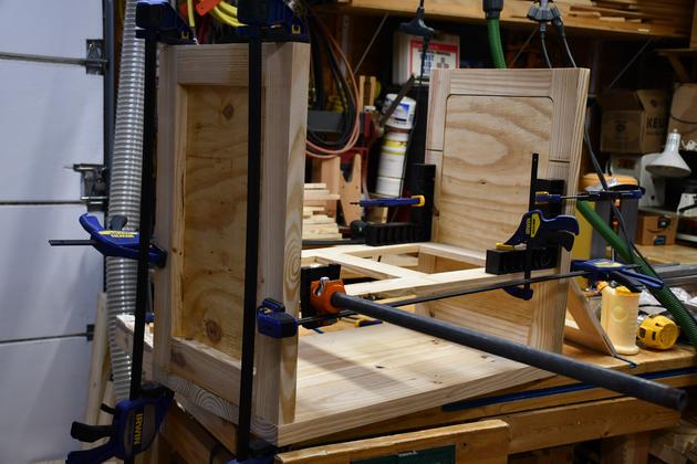
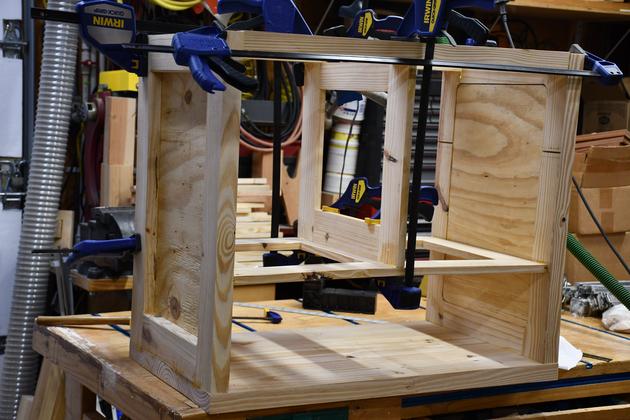
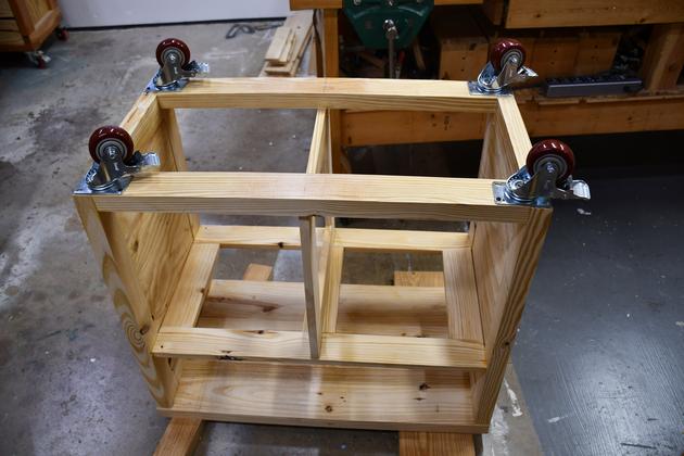
Gluing the stringers to the ends and VFrame.
BTW, you are looking at the back side of the cabinet.
|
|
From the right end.
|
|
Bottom painted, casters mounted.
|
|
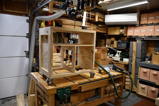
Back up on the bench for fine sanding.
|
|
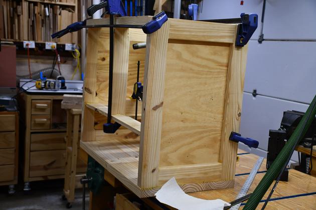
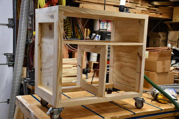
A little closer look at the bench frame.
|
|
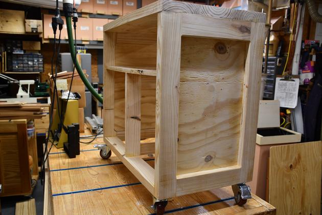
The back of the cabinet.
I'll leave the back panel off until I get all the internal painting etc. done.
|
|
Lathe riser spacer blocks, painted and ready to mount.
|
|
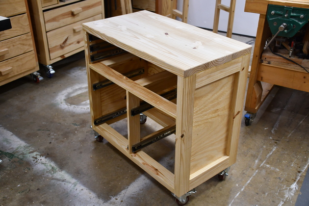
Back glued in, slides mounted, and down on it's own casters.
Ready to paint the top, I painted the bottom and sides, inside and out while it was up on the workbech.
|
|
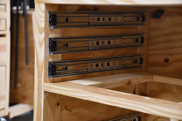
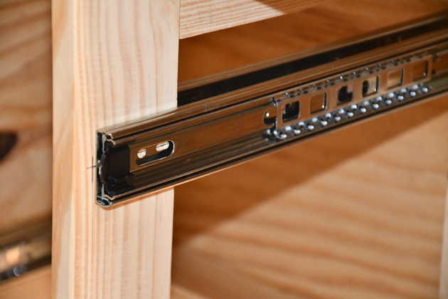
Closer look at the gouge drawer slides mounted.
|
|
When you mount slides on both sides of a realtively thin structure you need to use different screw holes or the screws interfear with each other.
|
|
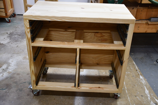
Center slides for lower chuck drawers, note there are two slide pairs mounted on 3/4" thick material and directly opposite each other.
When you do something like this you must be careful not to use the same mounting holes on each side.
|
|
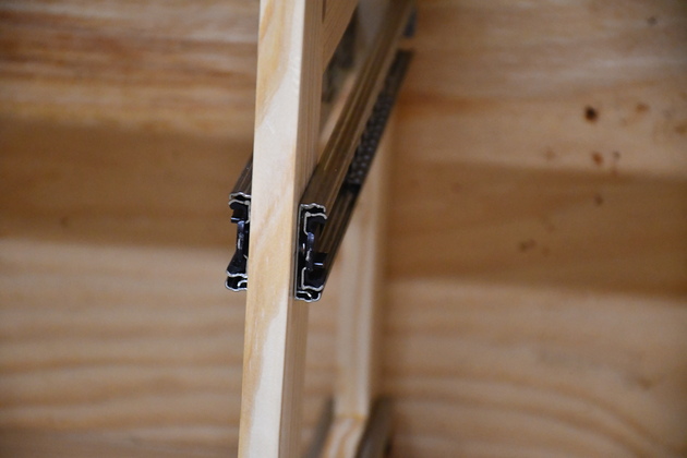
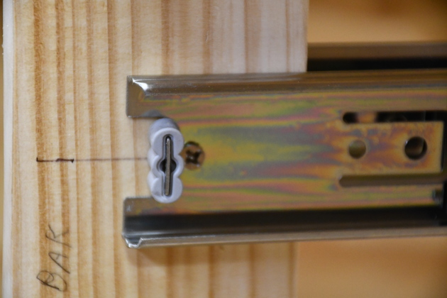
Slide mounted on one side of a 3/4" thick VFrame.
Note the screw is next to the bumper.
|
|
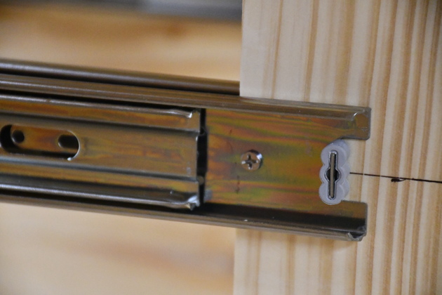
Slide mounted on the opposite side of a 3/4" thick VFrame directly opposite another slide.
Note the screw is about a 1" from the bumber so the two mounting screws are not in the exact same hole.
|
|
Ready to paint.
|
PM2014 Arrives
|
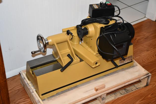
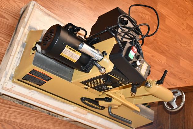
Backside of the PM2014 lathe on it's pallet.
The outside double cardboard box was plastic strapped down to the pallet, and inside, the lathe was cloth strapped to the pallet.
The lathe was also protected by 3 wooden 'U' frames which were stapled to the pallet.
The lathe weighs 108#, so I'll remove the head stock and tail stock before I put the bed on the new bench.
|
|
Pm2014 front.
Keep scrolling for more PM2014 pics.
|
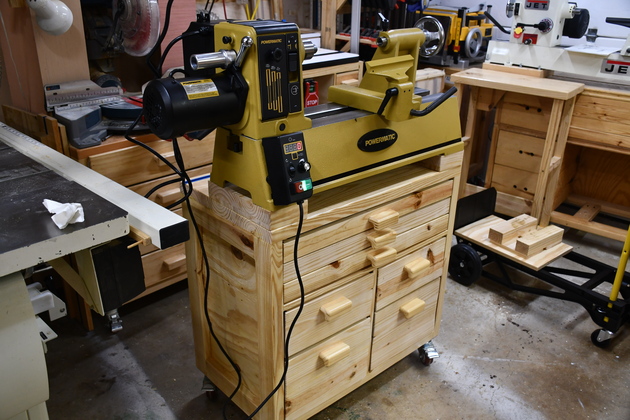
Finished
|
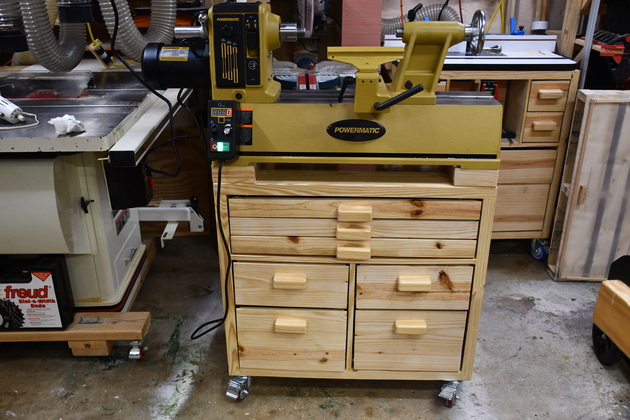
PM2014 install complete.
|
|
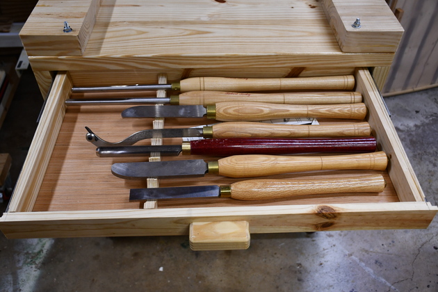
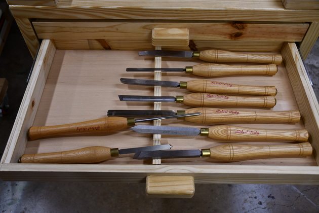
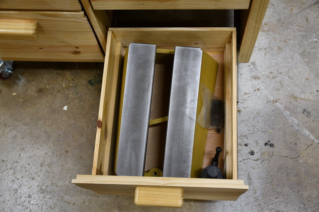
Top gouge drawer (#1).
I didn't glue the seperators, they seem to stay put by themselves.
See Lathe Bench Drawers.
|
|
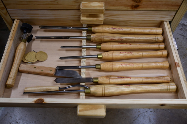
Number 2 gouge drawer (#2).
|
|
3rd gouge drawer (#3).
|
|
Drawer #4, small tools etc.
|
|
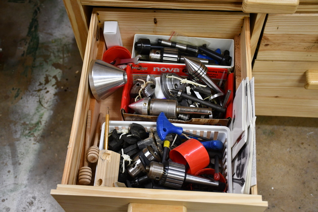
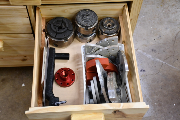
Drawer #6, one of the bottom chuck drawers.
|
|
Drawer #5, Chuck drawer.
|
|
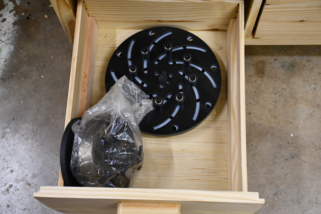
Bottom chuck drawer (#7) with bed extension.
|
|
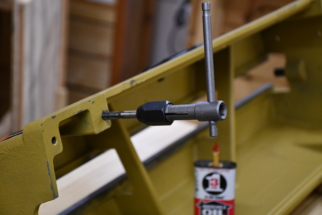
Cleaning out the threads in lathe bed mounting holes.
Preparing to mount the lathe bed on the bench.
Note I'll only use the inboard mounting holes, the outboard holes are too close to the end of the bench which has a 2x3 under it, so I can't run a bolt up from there.
The manual says its OK to only use two pairs of holes when mounting on a bench.
|
|
I cheated, removed the headstock, tailstock, and tool rest before installing the bed.
I built this little jig to hold the headstock while I'm mounting the lathe bed on the new bench.
|
|
From headstock end.
|

|
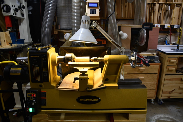
Closer look at the lathe on it's bench.
|
|
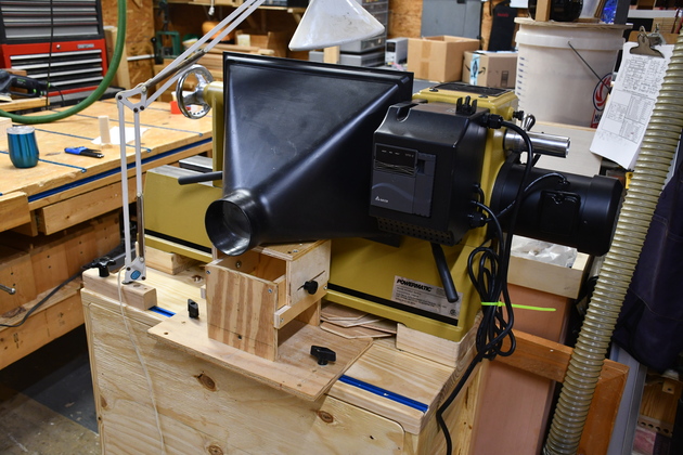
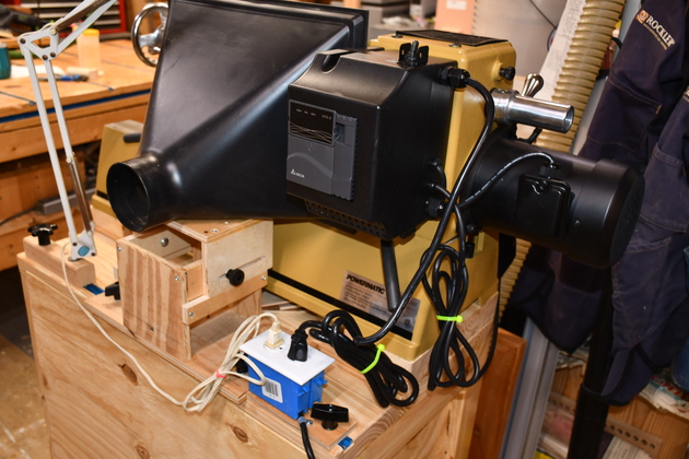
Lathe in the position where I use it, note the arm light, dust hood, and the Dust Automation Terminal just above and behind the lathe.
Since the lathe isn't connected through an Isensor, I manually operate the Dust Auto System.
|
Lathe Dust Hood, Arm Lamp, and Power
|
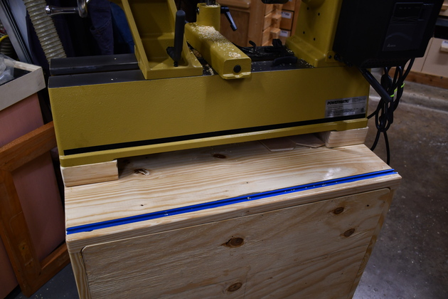
Back side of lathe bench showing tee track.
The tee track is 32-1/2" long and 1" from the back edge of the bench.
|

|
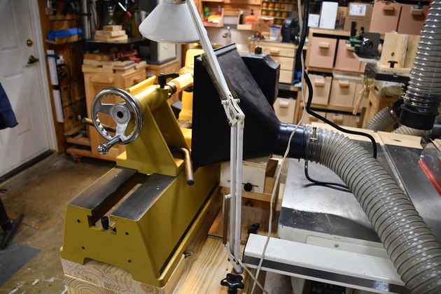
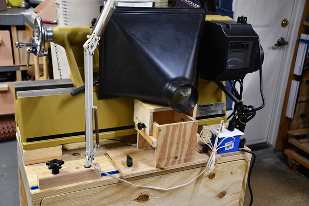
Back side of lathe bench showing arm lamp and dust hood.
|

|
The lathe dust hood on its mount.
I don't remember where I got the plastic hood, it is 14"X 11",
Rockler has one ($30) 12-1/2 X 16-1/2,
Amazon has one ($21.52) 13 x 16.
|
|
I had to modify the mount, heres a pic.
The PM2014 bed is about 2" higher than the Jet, and about 2" farther away.
So I added the slider on top of the tower to raise the mount point and allow it to bed moved closer to the bed and farther away to miss the tailstock handle when you slide the dust hood and mount on to the bench.
|
|
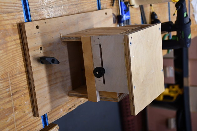
Just the mount.
Note the tee knob and bolt in the foreground are for the tee track on the lathe bench, lets you adjust the hood from side to side.
The other (round) knob lets you adjust the distance from the lathe bed to the hood.
|
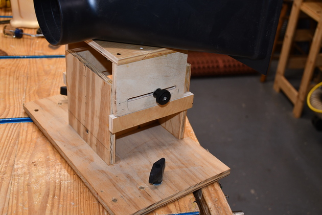
|
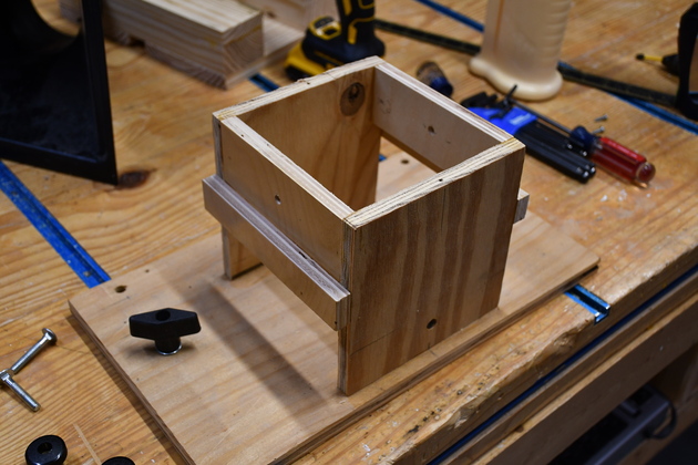
The base without the mount slider platform, that goes from side to side on the lathe bench.
The plywood base is 1/2" plywood, 15" long and ends up being 7" wide, the tower is 6" square and 6" high.
The bolts are 1-1/2" 1/4-20 carriage bolts.
|
|
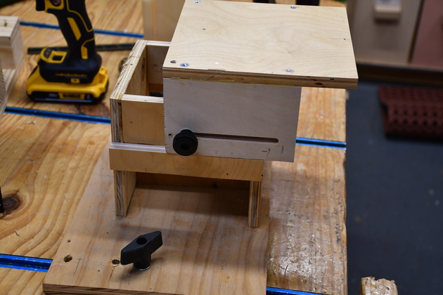
Mount with mount platform adjusted as far forward as it will go.
|
|
As you slide the dust hood mount onto the lathe bench, it is adjusted as far back as it will go to clear the tailstock adjuster lever.
|
|
Back of the lathe bench, showing arm lamp (left), dust hoot (center), this is before I added the power plug.
|
|
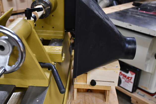
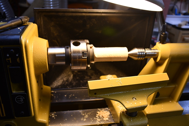
Here the dust hood is adjusted forward, touching to the lathe bed.
|
|
From the front, the lower lip of the dust hood is against the bed and the floor of the dust hood is flush with the top of the lathe bed.
I roughed down a 1-1/2 x 1-1/2 piece of pine to create some chips to test the dust hood.
|
|
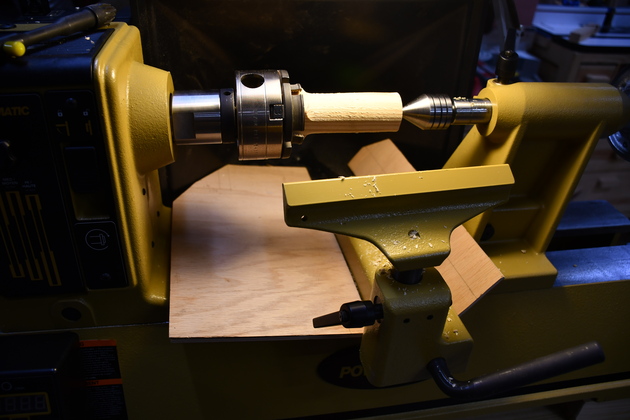
I normally keep these thin plywood strips in this position so chips don't fall under the lathe bed.
In most cases the in rushing air sweeps the ships into the hood's mount and they are gone.
|
|
I had to notch out the left side strip so it would be close to the tool rest.
|
Power Plug
I decided not to put a plug strip on the PM2014's bench, I used lots of plug strips on other benches because I had a lot of them.
And I wanted this to be able to move side to side on the bench's tee track.
|
|
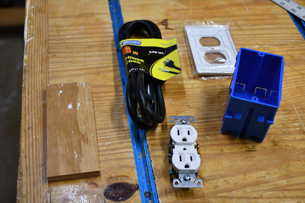
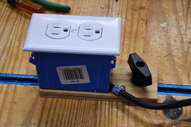
Parts for the power receptacle (plug).
The little piece of plywood is 3/8" thick, 2" wide and 6" long.
A Carlon single nail-in box (left over from Dust Collector Automation), single 125V 15Amp receptacle and cover, 6' 14AWG power cord.
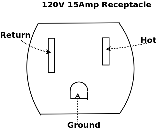
In case there is anyone not versed in house wiring, on the receptacle: (NEMA 5-15R) the left vertical hole (taller) is return (white), the right (shorter) vertical is hot (black), and the semi round hole (bottom) is ground (green).
|
|
BTW: I used a plastic cover plate and box because I had them, there are metal cover plates and metal boxes which would probably be a better choice in this instance.
You will also need a clamping strain relief for the electrical cable.
Note, I used a nylon strain relief.
|
|
|
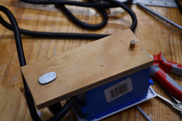
Bottom of completed power plug.
There are two 1/2" wood screws holding the box to the plywood.
You can see the bottom of the 1-1/2" X 5/16" tee bolt and the 1/4" wooden dowel.
The 1/4quot; dowel keeps the power plug aligned with the tee track.
|
|
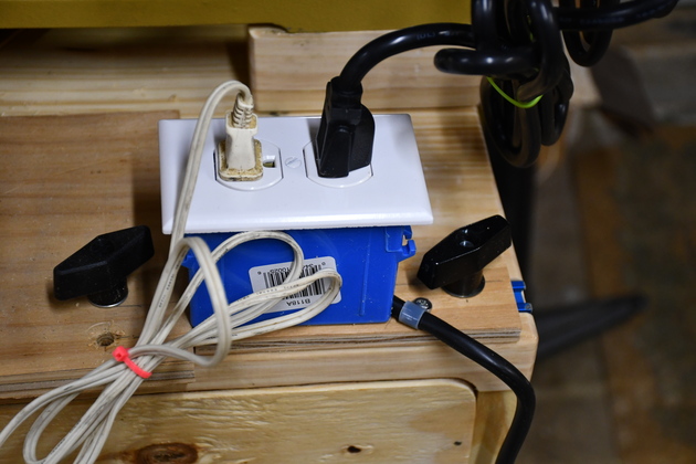
Completed power plug, in one of the tee tracks on my workbench.
Note, since I used a nail-in box (no internal strain relief), I used a nylon strain relief on the power cord.
|
Arm Lamp Mount
|
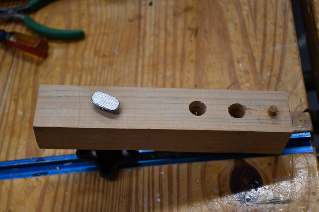
Bottom of arm lamp mount.
It is a 1-1/2 x 1-1/2" x 7" long piece of pine, with a 5/16" hole for a tee bolt about 1-1/2" from the left end, a 1/4" dowel about 1/2" from the other end, and a 1/2" hole drilled all the way through for the arm lamp pivot.
This Arm Lamp Mount has two 1/2" holes for some reason, I built it long ago and don't remember why it has the 2nd hole?
|
|
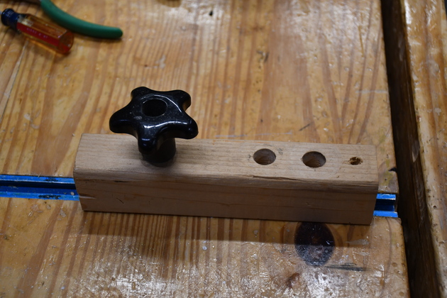
Top of arm lamp mount.
|
|
Back of the lathe bench showing arm lamp, dust hood, and power plug.
|
|
Close look at back of lathe bench.
|
|
The power plug mounted with lamp and lathe connected.
|