|
|
|
|
Cylinder Maker
|
02/05/16: Add Vert Adjuster.
07/06/15: Page Origin.
I frequently need to turn down lots of small cylinders from laminated stacks (making salt and pepper shakers) or make large dowels.
These laminated stack cylinders have the grain running across the cylinder instead of along the it's length, which makes it very time consuming and tedious to turn (for me anyhow).
Turns out this is something I do quite often anyway.
So I decided to make a jig to speed up the roughing cuts.
I also this would eliminate sawing off corners of the stacks and could cut the recessed threaded area with this jig.
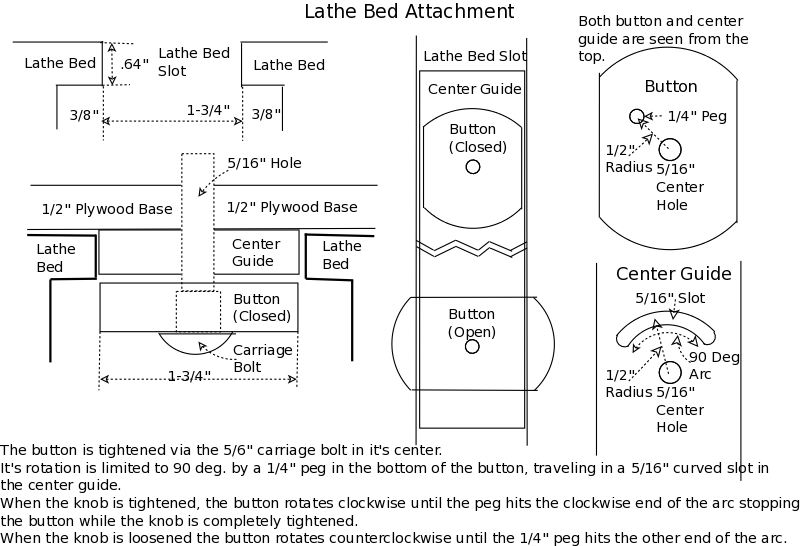
The primary considerations of this jig is securely attaching it to the lathe bed and making sure the top edges (along which the router sled travels) is parallel to the lathe bed (and thus to the head and tail stock centerlines).
The jig would be a plywood box, open on top, sitting above the lathe bed and in line with the headstock and tailstock.
The box would be on risers, above a plywood base secured to the top of the lathe bed with a guide bar protruding down into the lathe bed slot and two buttons with knobs holding it securely.
The hold down buttons would have a carriage bolt head imbedded into them which extends up through the guide bar and base into knobs on top of the base.
When the knobs are tightened the oblong button rotates, clockwise 1/4 turn (90°), and grabs the underside of the lathe bed.
The oblong button's rotation is limited by a peg, sticking out from the top of the button into 90° slots in the bottom of the guide bar.
When the knobs are loosened, the buttons rotate counterclockwise 1/4 turn, to align with the lathe bed slot to the entire unit may be lifted off the late.
The guide bar in the lathe bed slot, is slightly thinner than the thickness of the lathe bed sides, so the buttons will grab the lathe bed not the guide bar.
Guide Bar: 1/2", Lathe bed Edges: .64".
If anyone else wants to make one of these, first measure your lathe bed, the widthe of the slot, and thickness of the sides of the lathe bed.
Vert Adjustment
The original cylinder maker was primarily for salt and pepper shakers, about 2-1/4" diameter, but in 2016 I discovered I needed a wider variety of cylinders, some could even be called dowels.
I needed to make 1-1/2" dowels (hard to find at Lowes or Home Depot) and I wanted to use 2x4s which are 1-1/2" thick.
In order not to waste lumber I wanted to be able to adjust the bit right down on the flat surface of a 1-1/2 x 1-1/2" piece and round it off at that setting so the finished dowel would be very close to 1-1/2" in diameter.
So I came up with a mod to allow vertical adjustment of the router thus a wider range of cylinder diameters.
I removed the lathe attchemnt base and built an outer box that would fit aound the inner box (original box) with lock pins that would hold the inner box in fixed positions.
The lock pins would allow moving the inner box in 3/4" steps.
Then I glued lathe attachment guide bars on the new outer box.
|
Click on Pics for larger Pic
|
|
|
|
Click on either image for a larger printable image
|
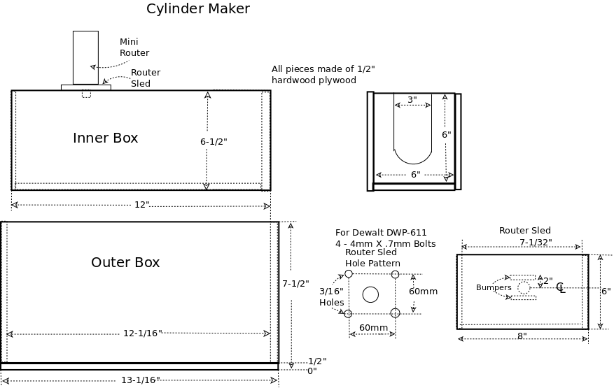
I am planning on using a compact DeWalt router (DWP611) so I will document the hole pattern for mounting it.
The smaller 1/4" router will work better with a small 1/2" or 3/8" mortise bit, I think.
Inner Box
|
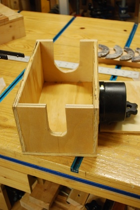
The box, made from 1/2" plywood, glued and screwed together.
The notches in the ends are for the headstock (near side) and tailstock (far side).
The dust port is on the right.
For dimensions please see the diagram above.
|
|
Back side of inner box.
|
Base or Outer Box
|
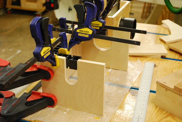
The outer box being glued together.
After I finished, I realized the smaller notches needed to be the same as the alrger notches.
|
|
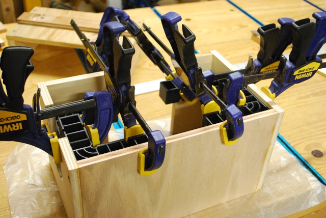
Last of outer box walls being glued.
Notice the Mini Clamp-Its being used to keep everything square.
ClampIts
Rockler also has larger Clamp-Its.
|
|
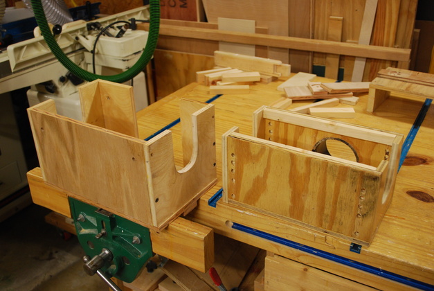
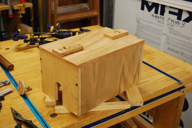
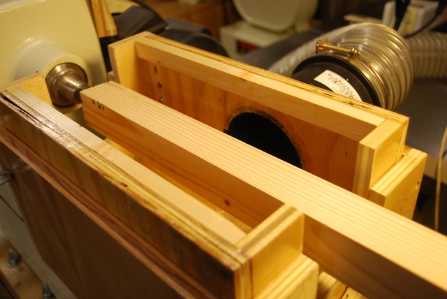
Outer and inner boxes complete.
|
The Guide Bar
|
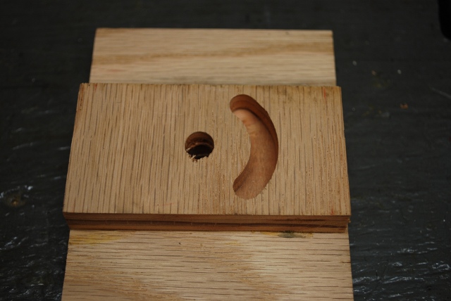
One end of guide bar, drilled and routed.
|
|
The guide bars glued onto the bottom of the outer box.
I used the Circle Maker to make the guide bars.
|
|
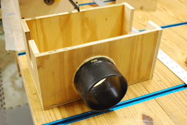
Base on the lathe bed with the guide bar glued and in place in the slot.
|
The Buttons
|
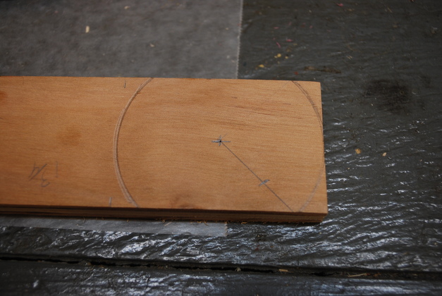
The buttons are 1-3/4" wide, same as the guide bar, 2-1/2" long, and made from 1/2" birch plywood.
Here you can see the rounded ends and center marks.
You can also see the 45° diagonal and the mark for the 1/4" peg hole.
|
|
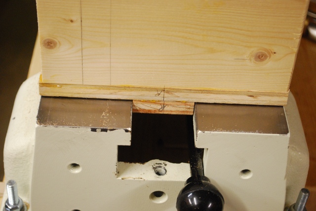
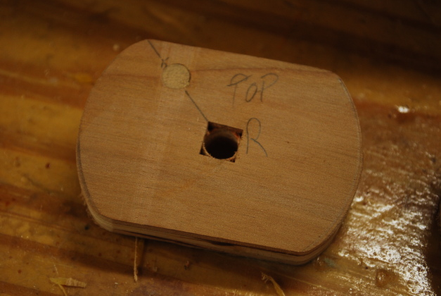
I'm going to use 5/16" carriage bolts as axles, so I needed a 5/16" square hole for the shoulder of the carriage bolt.
I used my mortiser, after all it drills square holes and I have a 5/16" bit.
|
|
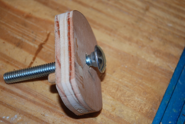
You can see where the carriage bolt's shoulder goes into the square hole in the button.
|
|
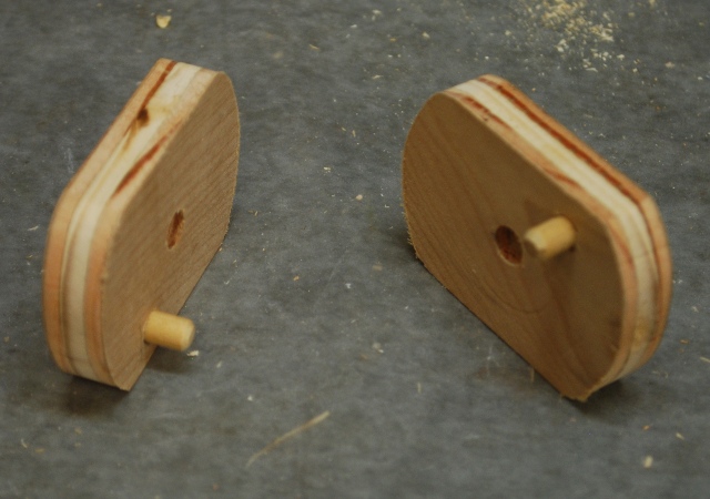
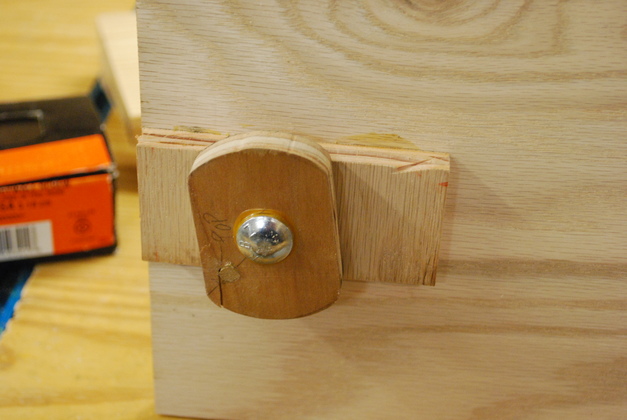
Button on the guide bar in unlocked position.
|
|
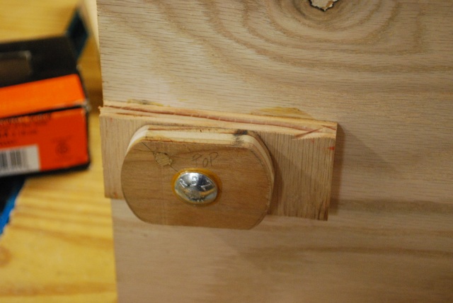
Button on guide bar in locked position.
|
|
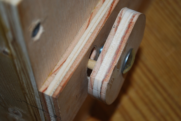
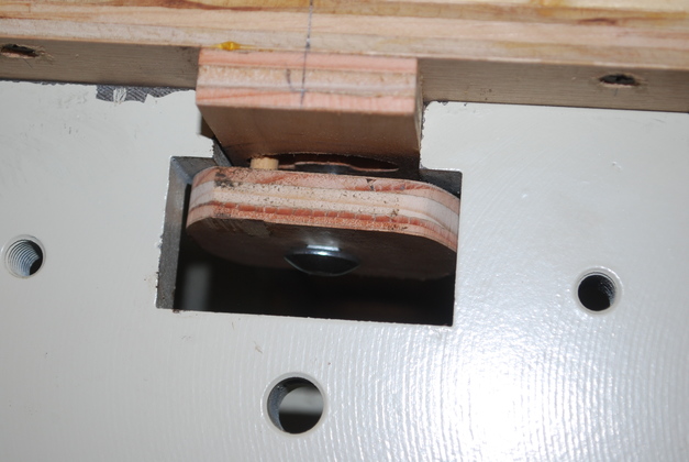
Button on guide bar, you can see the 1/4" peg inserted into the slot in the guide bar.
Remember the lathe bed lip is thicker than the guide bar thats why the space under the button.
|
|
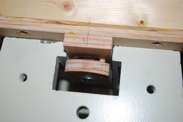
Base and guide bar sitting on the lathe bed, you can see how the button clears the lathe bed slot.
You can even see the peg at counterclockwise end of it's travel, as the button is tightened it rotates clockwise, the peg moves in the slot until it hits the other end.
|
|
The button rotated clockwise to hold the jig down on the lathe bed.
Note the peg is in the clockwise end of the slot.
Also look at the overlap of the ends of the button under the lathe bed lip.
|
|
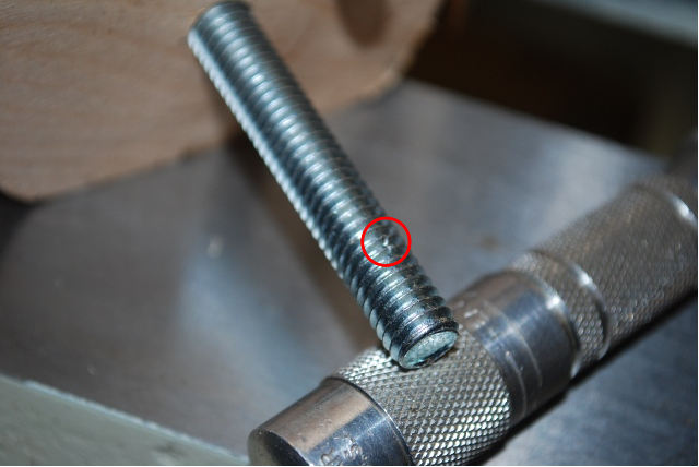
Carriage bolt, I had to put a dent (red circle) in the carriage bolt, to increase friction, so it would always turn (enough to rotate the button on the bottom) as the knob on top is tightened or loosened.
I used a center punch (the one under the end of the bolt) to make the dent.
|
|
The top of the carriage bolt inside the outer box.
|
|
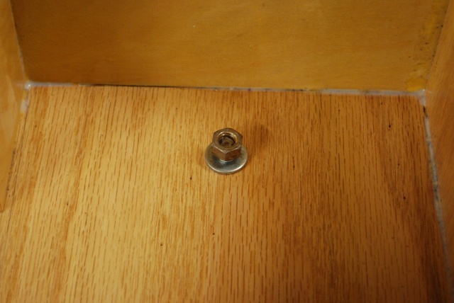
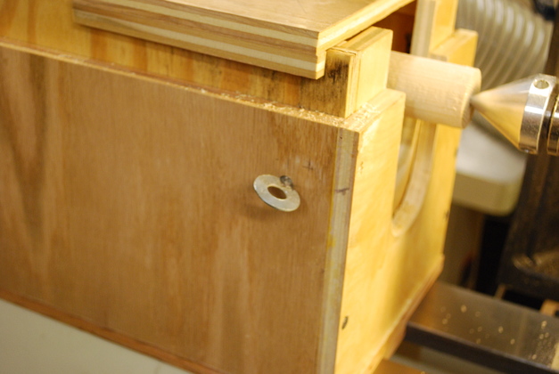
Nut on top of carriage bolt seen through hole in inner box.
I elongated the hole so I can move the box while I have a long cylinder mounted.
|
Lock Pins
|
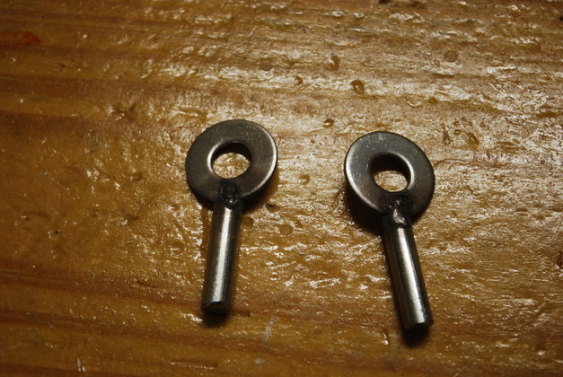
I made lock pins to hold the inner box in position in the outer box.
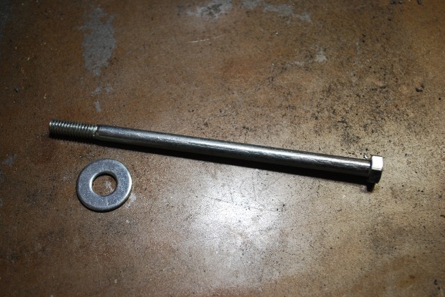
I used a 5/16" bolt and 3/8" flat washers.
|
|
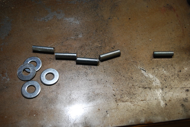
Cut the bolt into 1-1/4" long pieces.
|
|
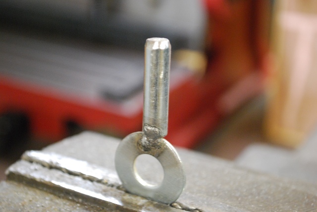
Welded the flat washers to the end of the 5/16" bolt and shazam, I had lock pins to hold the inner box in position.
|
|
A lock pin sticking through the outer box.
|
|
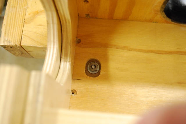
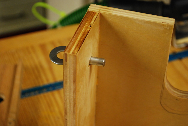
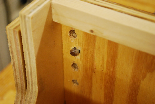
One lock pin sticking through into inner box, note other holes on 3/4" centers for adjustment.
|
The Router Sled
|
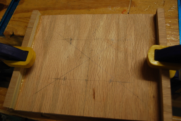
Base of the router sled, you can see the center mark and router mounting holes.
The DeWalt Compact router holes are in a square, 2-3/8" apart, the center hole is 1-1/8" in diameter.
This is the bottom of the sled, the raised pieces on either side are guides that keep it centered on top of the box.
|
|
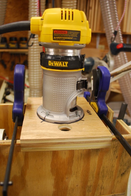
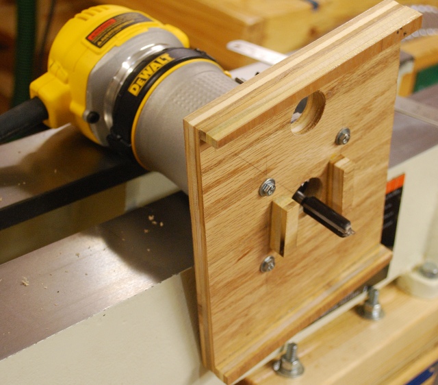
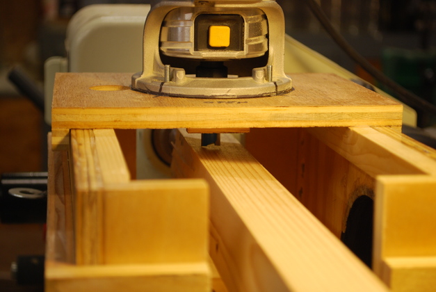
Router mounted on the sled.
The black marks are to line up the bolts that hold it down.
The hole in the sled on this side of the router, is to check the alignment when I'm cutting a slot around a cylinder (for threads etc).
|
|
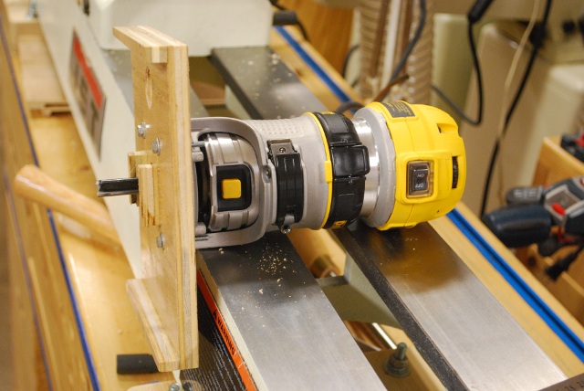
Router and controls while mounted on the sled.
|
|
Router sled with router mounted, the small blocks on each side of the router bit are bumpers that keep it from sliding off the end of the box.
|
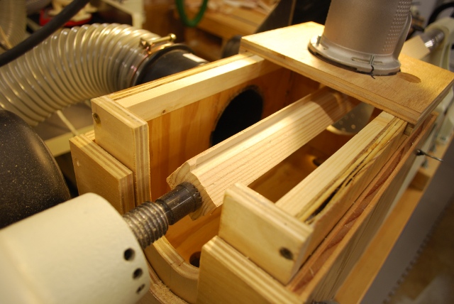
Making Dowels
|
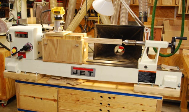
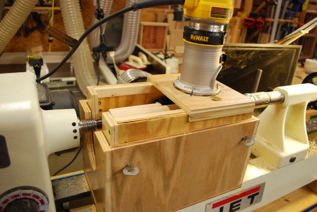
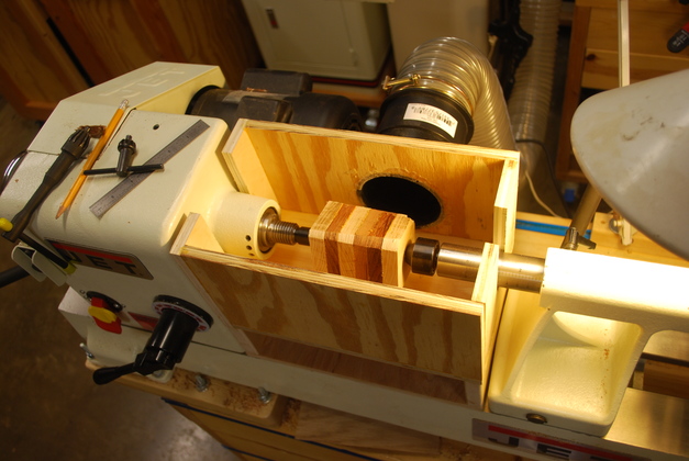
As it appears when working.
You can see the inner box, outer box, and locking pins holding the inner box in position.
Here I'm making a large dowel that will be sawed up for caps and bushings on Paper Towel Holder.
|
|
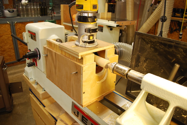
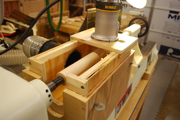
From the right end.
|
|
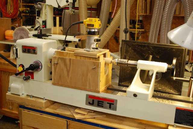
A wider shot.
|
|
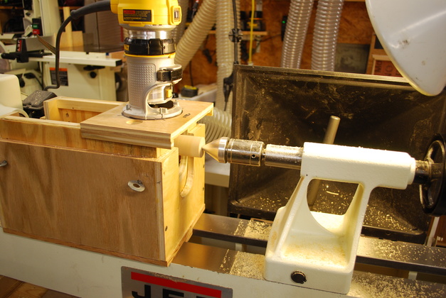
Locking pin in position.
|
|
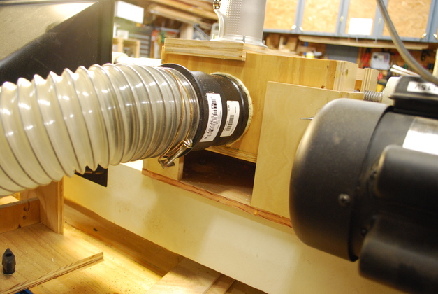
Dust port, note the slot in the back of the outer box so the port can travel up and down with the inner box.
|
|
Square stock about to become a dowel.
|
|
Start out by adjusting the bit right down on the flat surface of the square stock, the move the sled from side to side.
|
|
You can just see the first cut has been made.
|
|
Dowel being rounded.
|
|
Tail stock holding end of dowel.
|
|
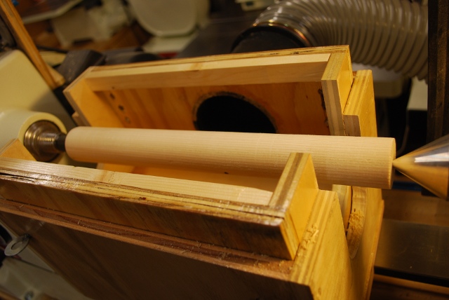
A finished dowel.
Note the notches in the tail stock end are both the same as the headstock notches.
|
Laminated Stacks
|
A square stack mounted.
|
|
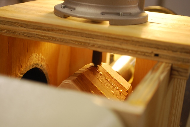
A look at the bit as it begins to cut.
|
|
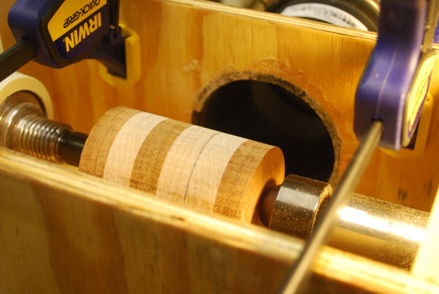
Cylinder being cut, you can see the cuts along the cylinder and where the the bit hasn't been yet.
I make passes up and down the length of the cylinder, then turn on the lathe and slowly move the sled from end to end, smoothing out the cuts.
|
|
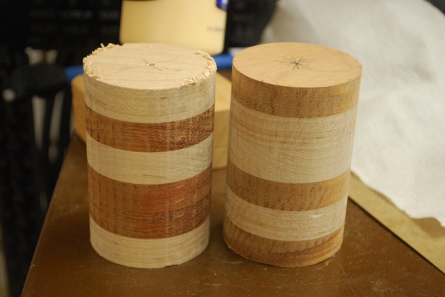
A pair of cylinders, exactly the same diameter, cut in less than 6 minutes.
|
|
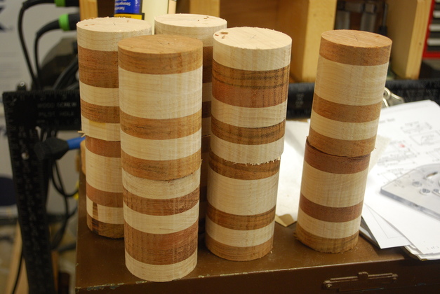
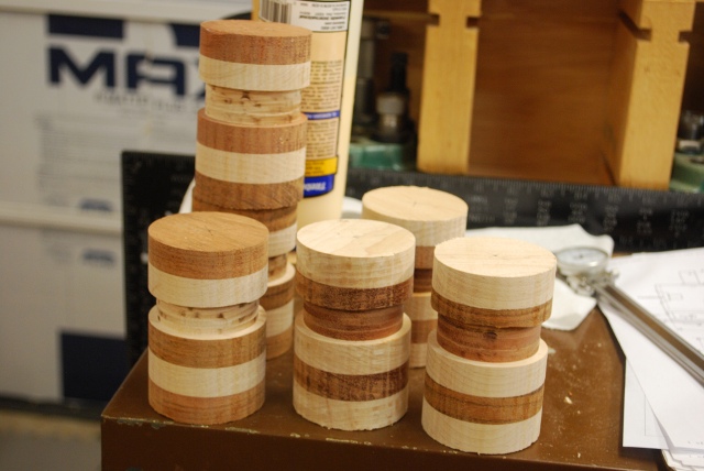
A pile of 8 exactly identical diameter cyclenders.
The two on the right are slightly smaller, I had buggered them up and used the cylinder maker to clean up my mess.
|
|
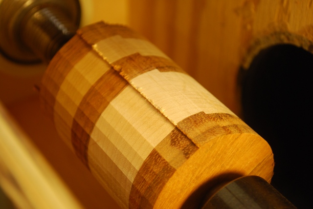
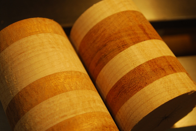
Closer look at two cylinders just off the cylinder maker.
|
|
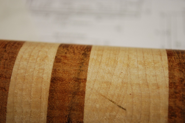
Close as I could get, a little sanding/polishing and this surface is ready to go.
Notice no cross grain tear out!!!
|
Cutting Slots
|
Pencil mark on right side of slot.
The lower (on the left) side of double layer will be machined down about 3/16" for the threaded area.
|
|
Slotted cylinders, ready for next step (sawing off the lids and threadding).
|