Lifting Mechanism
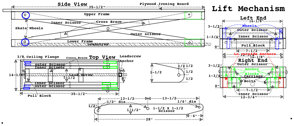
I looked around for ideas for a lift mechanism that would be stable and keep the ironing board parallel to the floor as it was raised.
I found a few articles about scissor lift and that looked like just what the Dr. ordered.
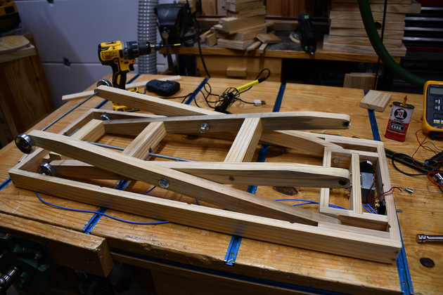
One end of one of a pair of scissor pairs is anchored the other end rolls on wheels.
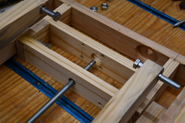
One end of the leadscrew pulls against a pull block attached to the axle on the inner scissor the other end pulls against an anchored block with a thrust wassher or bearing.
So the lower end of the scissors is pulled together forcing the upper end of the scissors to lift.
I'm using a 3/8" threadded rod as a leadscrew to raise/lower the ironing board same as I did with the scissor lift mechanism in the shop.
Remember, your scissors should all be exactly the same size and the holes in exactly the same position.
The anchored end of all 4 scissors as well as the cross point have a bronze bushing 3/8" ID X 1/2" OD X 1" long.
The axle for each of these bushed holes is a 3/8-16 hex bolt.
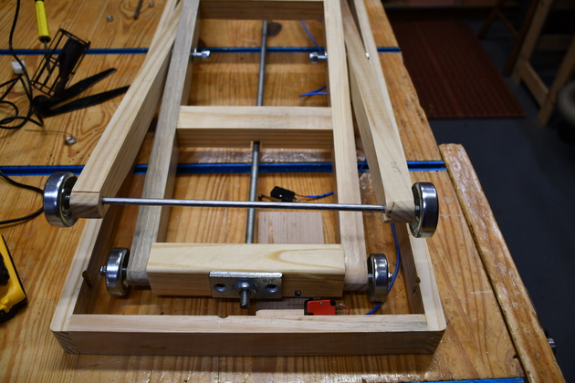
I bought conveyor skate wheels (pack of 10 Amazon.com $9.70) (1-15/16" diameter and 1/4" axle).
These conveyor skate wheels have ball bearings, eliminating the need for bushings or bearings on their axle passing through the scissor ends and pull block.
Crank
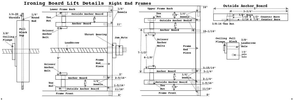
Hand crank for the leadscrew: Leadscrew protrudes out the right end about 2-1/2" and put two 3/8-16 nuts jammed together.
I didn't list the crank parts, it can usually be built from scrap around the shop like a piece of oak flooring, a 1" and a 3/8" dowel.
A piece of oak flooring, a 1" dowel rod, and a #8 X 2" wood screw.
More info on making hand cranks.
Lumber Prep
|
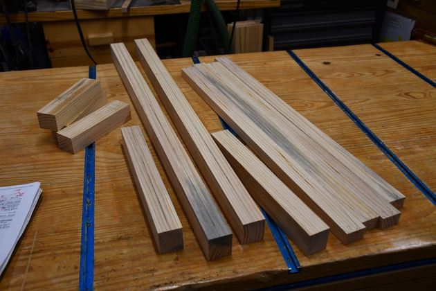
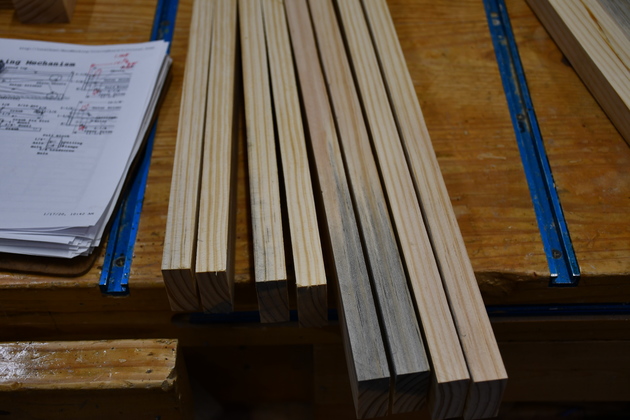
All the frame and scissors ripped.
|
|
Frame & end pieces marked for resawing.
|
|
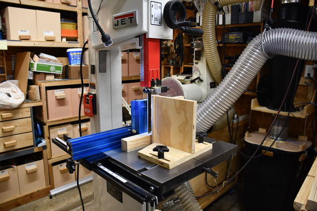
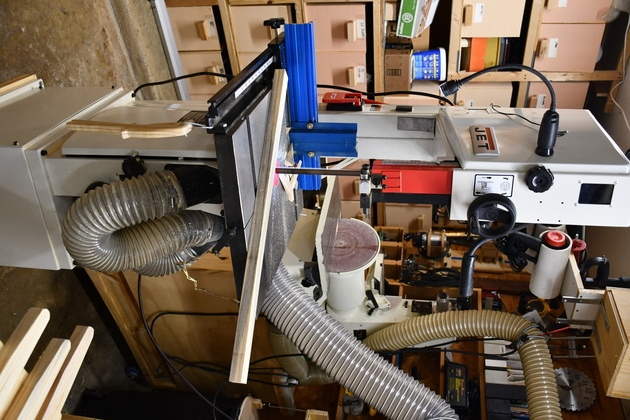
Resawing frame sides ends.
|
|
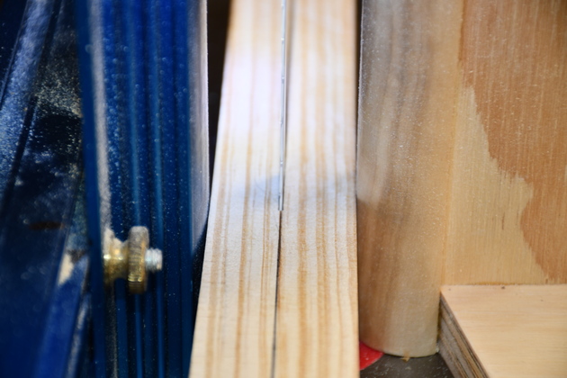
Closeup of resawing.
|
|
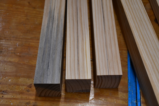
The sides and end pieces of the frame, resawn.
|
|
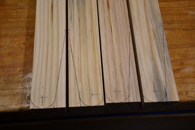
Scissor ends marked for sawing and drilling.
|
|
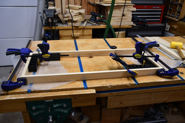
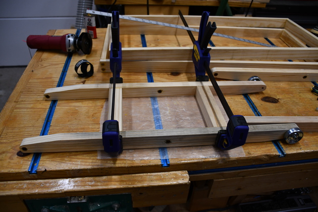
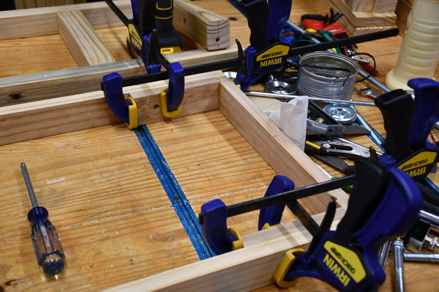
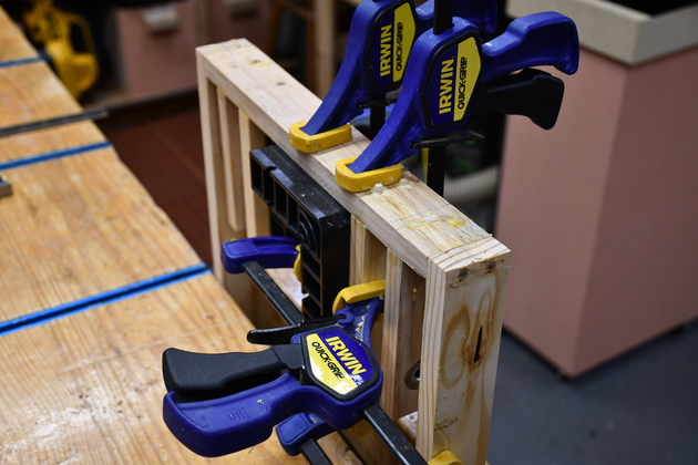
One of the frames being glued on the workbench.
I didn't take any pics whild I doweled these corners, sorry.
|
|
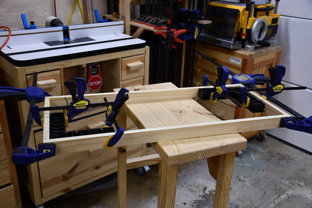
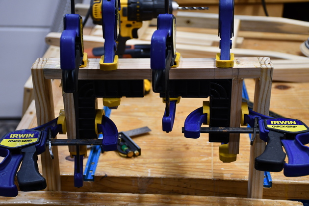
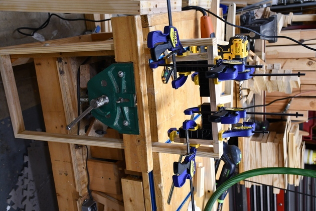
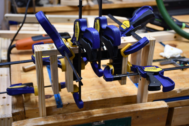
The other frame being glued on the side table.
|
|
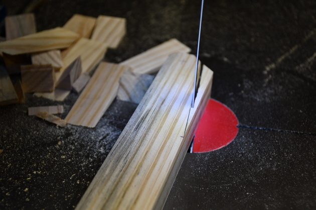
Sawing the scissor ends.
|
|
Closer look at sawing scissor ends.
|
|
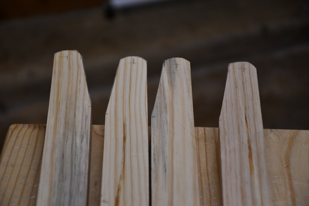
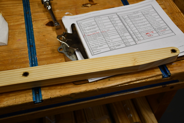
Scissor ends after sawing tapers.
|
|
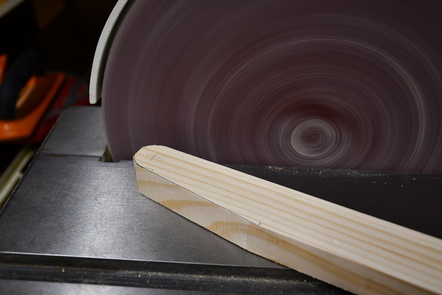
Rounding the sawed scissor ends on the sander.
|
|
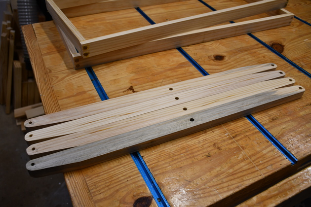
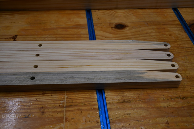
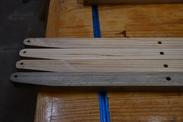
Scissors with all holes drilled.
|
|
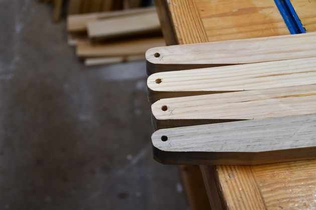
Closer look at 1/4" holes in scissor ends for wheel axles.
|
|
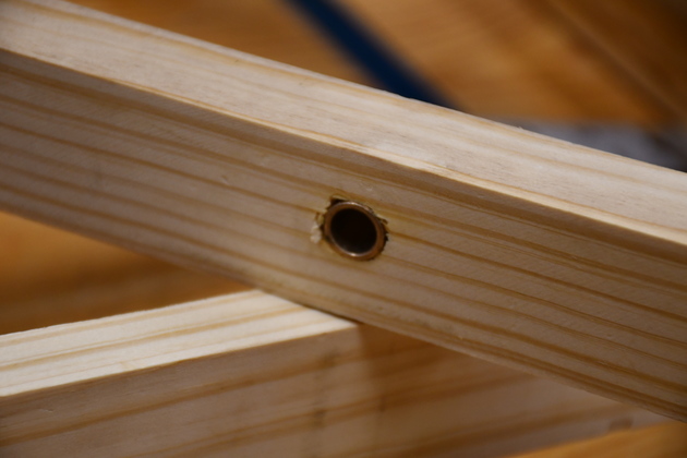
The 1/2" holes for 3/8" bushings.
|
|
You can see the smaller (1/4") holes in left end of scissors and 1/2" hole for pivot in center of scissors (right end).
|
Metal Working
|
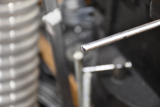
Sawn off 1/4" axle rod.
|
|
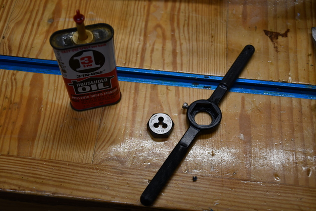
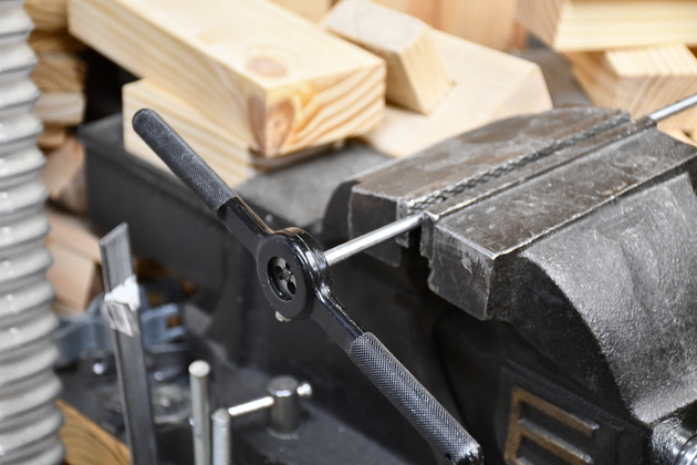
1/4-20 die, die handle, oil, ready to thread end of 1/4" axle rod.
|
|
Cutting 1/4-20 threads on end of short 1/4" axle.
|
|
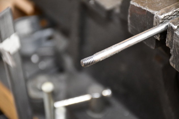
Tapped end of short axle.
|
Scissors
|
Gluing cross braces between inner scissors.
|
|
3/8 bushings installed in scissor.
|
|
3/8" bushing installed in scissor pivot (center) hole.
|
|
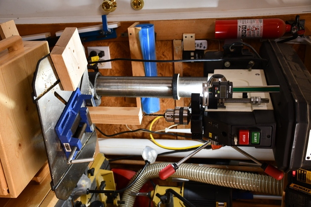
Drilling 1/4" guide hole in end of pull block.
I'll finish with a long 1/4" drill but it wouldn't fit in the drill press without removing storage cabinet.
You'll note, I did remove all the stuff under the drill press table and on top of the cabinet.
|
|
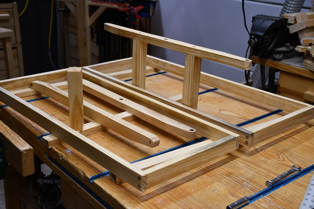
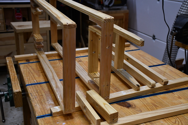
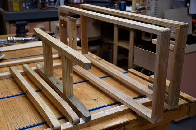
Major lift parts, ready to assemble.
|
Anchors
One end (right) of each scissor will be anchored to the frame, the other end rolls on wheels as the lift rises.
|
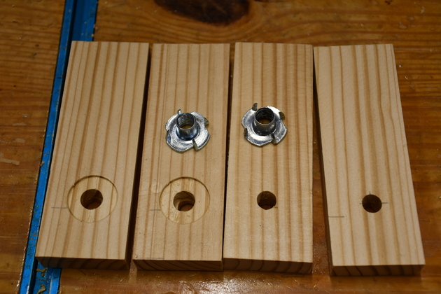
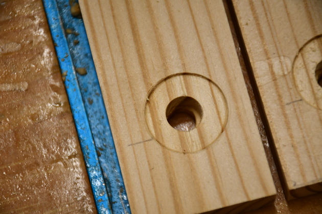
Scissor anchor boards for one frame, you can see the counter bores in the outside pieces (on left) for the 3/8-16 tee nut flanges.
The outside anchor boards will be glued against the lower frame thats why the tee nuts must be flush.
|
|
Closer look at tee nut counter bore.
I had to counter sink the outside flange of the tee nuts so the anchor would glue flat to the inside of the frame.
These outside anchors are 5/8" thick to match the width of the wheels.
|
|
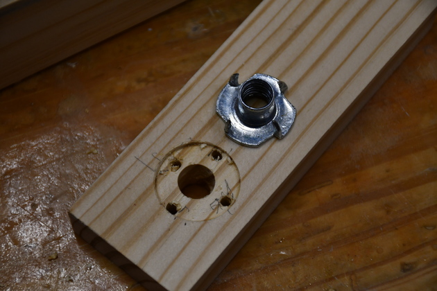
I also drilled pilot holes for the points on the tee nut so this 5/8 pine wouldn't crack.
|
|
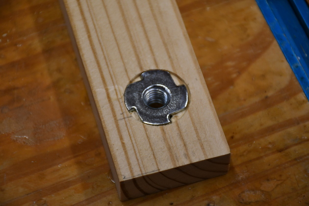
Tee nut pressed in, the back of the flange is flush with the anchor board's surface.
|
|
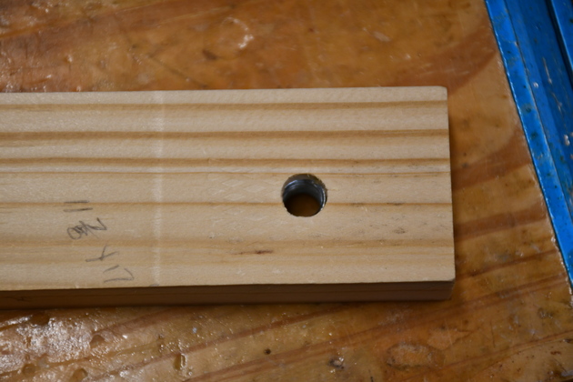
From the other side you can see the threads of the tee nut.
|
|
Gluing in the outside anchor blocks, with their tee nuts against the frame.
|
Upper Frame
|
Gluing outside anchors in upper frame.
Note ClampIts keeping everything square.
|
|
Looking farther at the upper frame anchor glue up.
|
|
Gluing inside anchors on the upper frame.
|
|
Even using the smaller ClampIts, I had to overlap them to glue two at once.
|
Painting
|
All the wooden parts (except the ironing board itself) being painted.
Just 7 wooden assemblies.
|
|
Other angle of the wooden parts being painted.
Note: you can see the little limit switch platform glued into the near end of the lower frame.
|
|
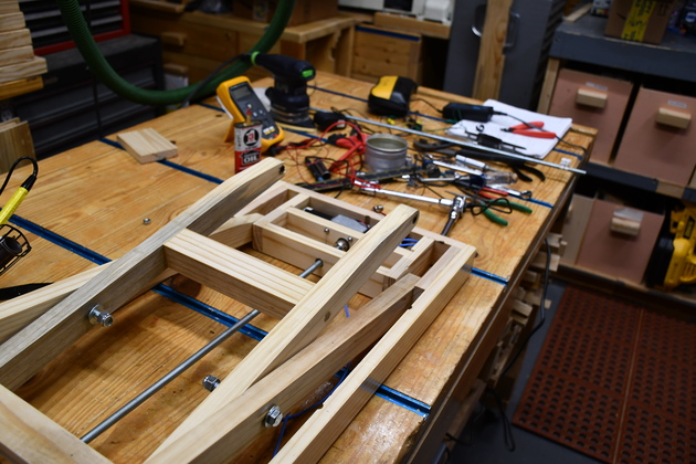
Trial version with gearmotor as lift power.
|
|
I couldn't get the little gear motor to raise the board with any load (like an iron).
|
|
Other than that, the lift is the same with a longer leadscrew (3/8" threadded rod).
|
|
Left end with skate wheels and 3/8" ceiling flange.
|
