| 
| 
| |
|
Scissor Lift
| |||
|
|
|
| |
|
Scissor Lift
| |||
| Build Info | Details | Scissors | Bushings |
| Finished | Crank | Work Cart |
I am planning on building an Ironing Board, for Betty, with storage and the board height is adjustable.
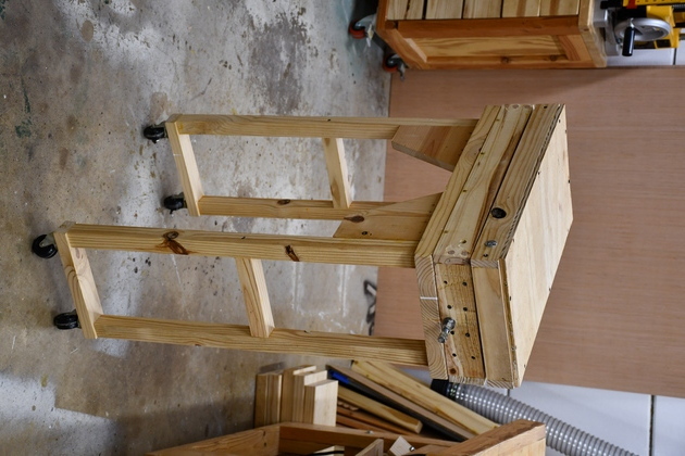
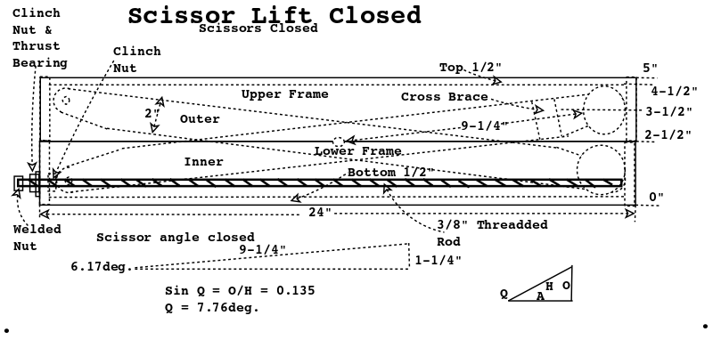
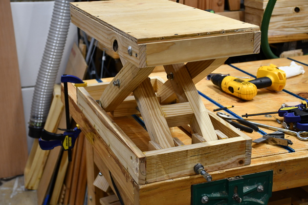
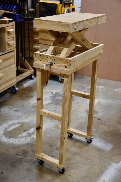
The lifting part will be a scissor lift like this shop prototype.
So, as a protoype, I am making a scissor lift for the workshop.
The original design was influenced by Marius Hornberger and his Patrion website.
I don't have ash to build from so I'm using my old standby Southern Yellow Pine.
My scissor lift will sit on top of the 12X24 work cart which used to fold up but I am making it rigid.
The top of the work cart is 24" long and 12" wide.
When I am using my drillpress, I frequently need to support the end of a long piece.
I used to make custom spacers that sat on top of the side table but it is a pain to store them etc.
I though an adjustable scissor lift would ba a handy addition to the shop.
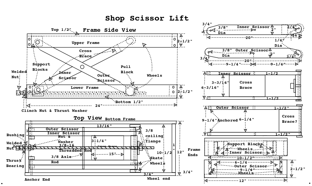
The work cart is 36" high, the typical height of work pieces on the drillpress is 48-1/2" The frame of the scissor lift is 5" thick, so I need about 0 - 8" lift range. The Ironing board needs about 6" so they are in the ballpark.
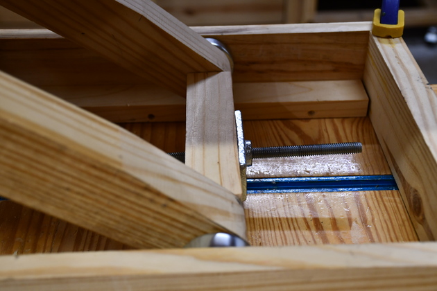
The scissors will be anchored at one end, with a 3/8" rod, and the other will have 2" skate wheels running on a either the top or bottom wheel runners. All moving joints will have 3/8" copper bushings except the wheels which have their own ball bearings. The anchor end of the scissors will have a 3/8" carriage bolt with 3/8"ID copper bushings (copper pipe). I know copper pipe isn't as hard as a real bushing but I think it'll work for this. The anchor end of the frame will have a pull block glued to the frame end piece with a 3/8" LeadScrew (threadded rod), 3/8" copper bushing, two 3/8" jam nuts and 3/8" thrust washers. The pivot point at the center of the scissors will also have 3/8" carriage bolts with 3/8" copper pipe as bushings. The rolling end of the scissors will have a 1/4" steel rod as axle with skate wheels with ball bearings.
Originally I designed the upper frame piece narrower than the lower but soon discovered that wouldn't work. So I built another upper frame the same dims as the lower and with 4 support blocks, on the anchored end, to anchor the outside scissor. This shop version has a plywood top on the upper frame for the wheels to run on.
I measured the torque required to turn the crank with nothing on the scissor lift and got 3.64 in-lb, or .411264763 nm (1 in-lb = 0.11298 N-m) = 1.15207 kg-cm. Also, kg-cm to N-m? = 10.197162129779 (1 kg-cm = 0.09807 N-m)
|
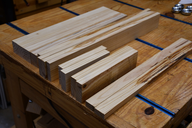
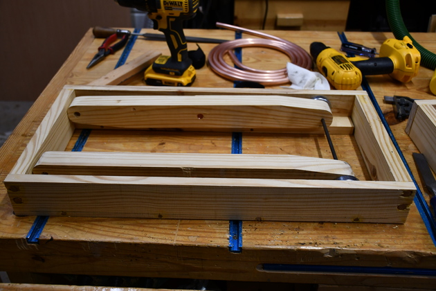
Frame pieces and scissors cut out. |
|
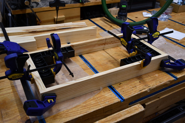
Bottom frame in glue clamps. Note the ClampIts holding the frame square. |
|
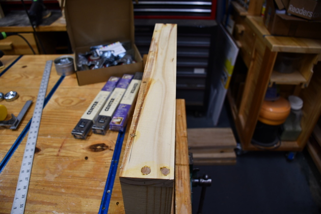
Frame with dowels being glued. |
|
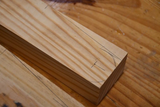
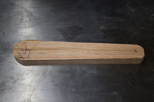
1-1/2" X 2" cut 22" long and marked for rounding and its axle. |
|
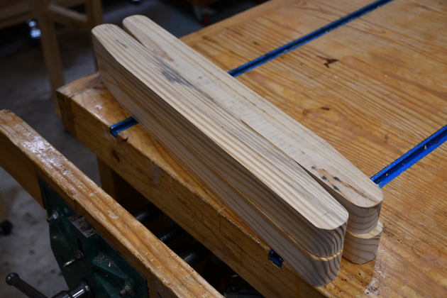
All 4 scissors after sawing and sanding, ready to drill. |
|
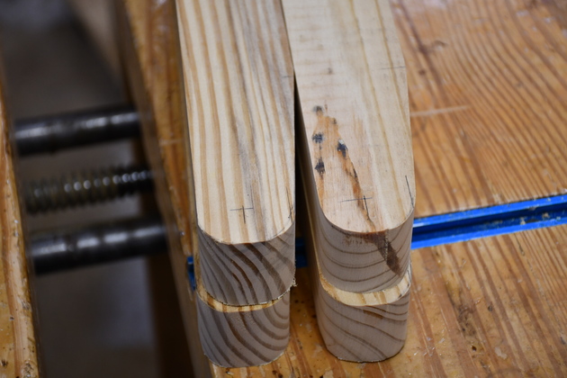
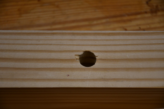
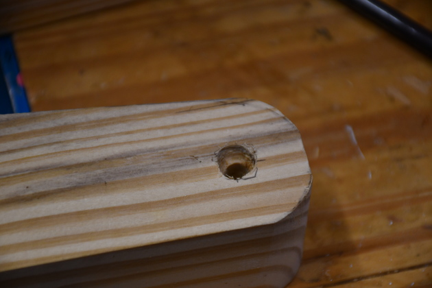
Closer look at end of scissors. Note I marked the drill hole before sawing. |
|
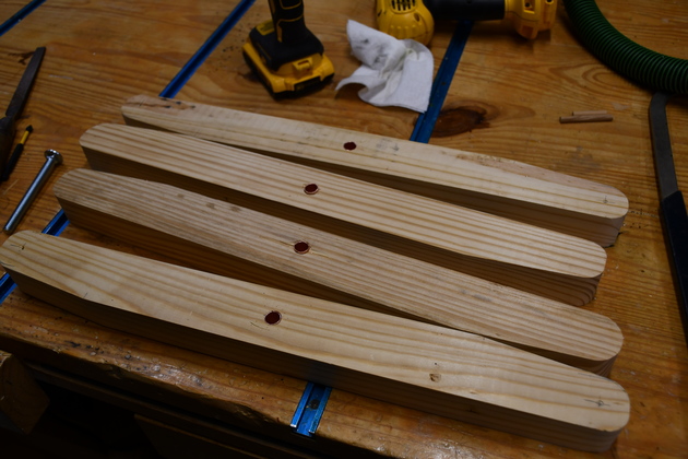
Center pivot copper bushings inserted in all scissor pieces. |
|
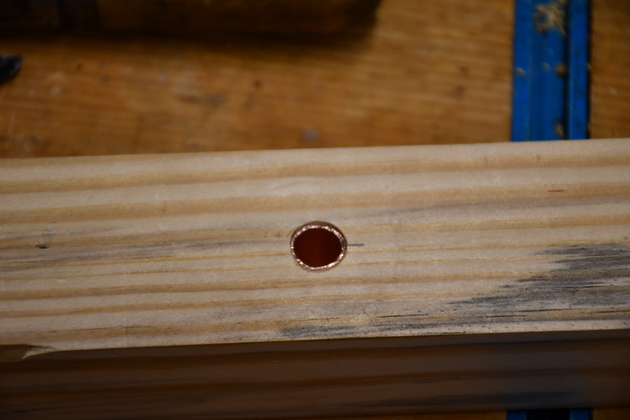
Center pivot hole drilled. |
|
Close up of center pivot copper bushing inserted. |
|
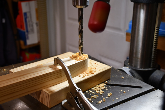
Drilling end axle hole in scissor on drill press. |
|
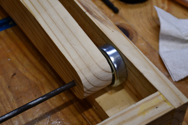
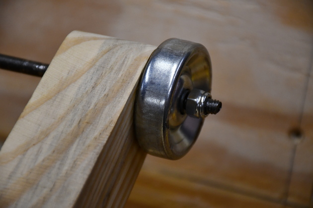
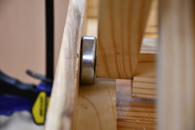
Closer look at one of the skate wheels and axle on the outer scissor.
|
|
I had to counter sink the scissor for the skate wheel axle. |
|
Outer scissor fit inot lower frame with wheels and 1/4" axle. |
|
Outer scissor in lower frame. |
|
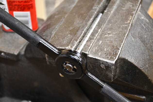
Threading the end of 3/8" rods for axles. |
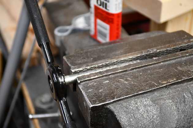
|
Different angle. |
|
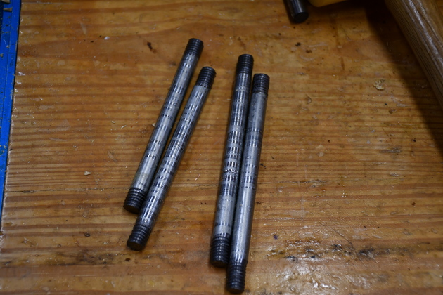
3/8" axles with threadded ends. |
|
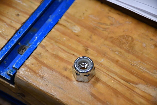
A 3/8" clinch nut, you can see the nylon insert at the top. When the threads contact the nylon insert they tighten up a little and wont work loose. |
|
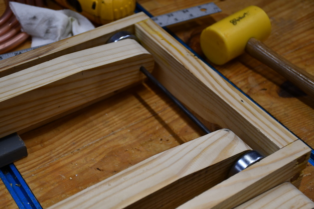
The scissors in the lower frame. Note axles with washers and clinch nuts. |
|
1/4" axle with threadded end and a clinch nut. Note the clinch nut holding the wheel on. |
|
Outside scissors attached to top frame. |
|
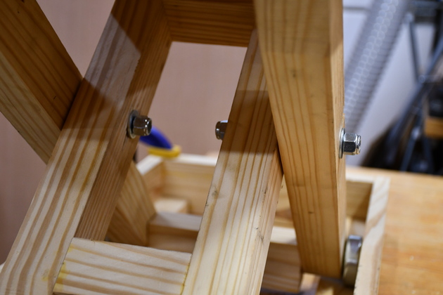
One of the 3/8" scissor axles with it's washer and clinch nut. |
|
Both scissor axles with nuts washers. |
|
One of the lower skate wheels. You can just see the end of the pull block to the right of the scissor and on the 1/4" axle. |
I will use copper bushings for the scissors and the crank end of the threadded rod (AKA leadscrew).
The scissor bushings will be at the anchor end and at their center.
The skate wheels (conveyor rollers) have their own roller bearings so I'll just use 14/" steel rod as an axle which won't turn.
Also note, in the pic, above the end of copper you can see a 3/8" ceiling flange.
These are for hanging things from the ceiling with threadded rod.
|
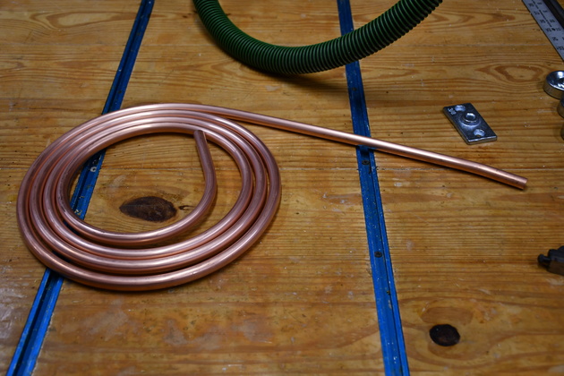
I bought a 10' coil of 3/8 copper pipe for bushings. Its getting where 3/8" ID copper pipe is hard to find. If your careful when you unroll it you can get it fairly straight. It shouldn't be a big problem since the bushings will be relatively short (2" and 4" max). The vendors aren't religious about keeping the terms "pipe" and "tube" straight as far as their dimensions go. |
|
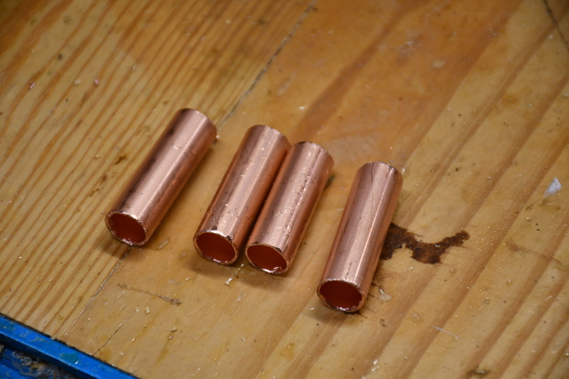
1-1/2" long bushings from 3/8" copper tube. |
|
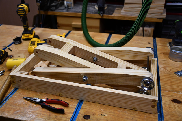
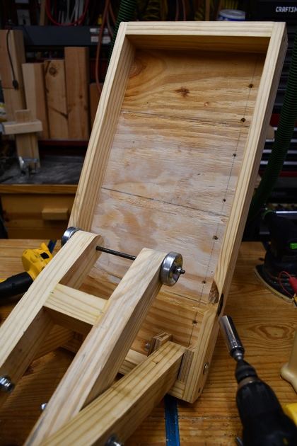
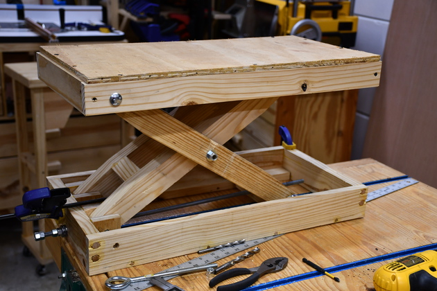
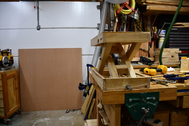
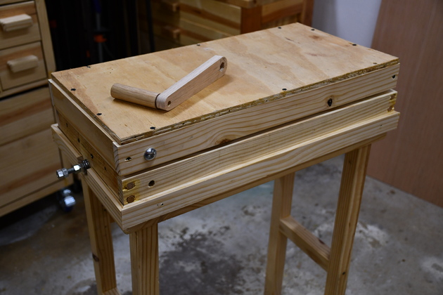
The scissor lift, assembled, sitting on my workbench. I do still need to att the skirt around the bottom frame so it won't slide around on top of the work cart. |
|
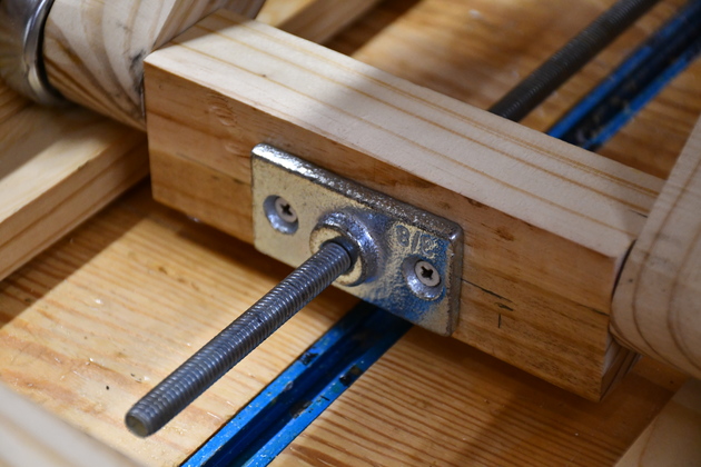
End of the adjustment rod sticking out of the ceiling nut. |
|
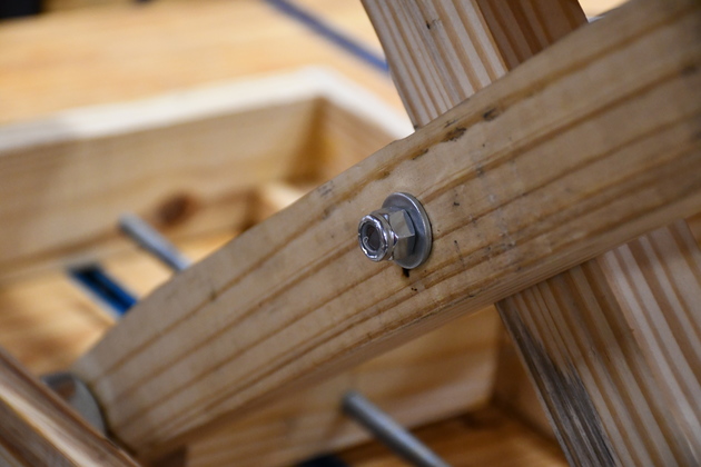
Another shot of the ceiling nut outside the pull block. Note the ceiling nut pulss against the pull block so the screws don't actually have any pull on them. |
|
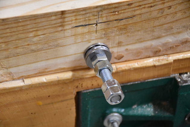
Other end of the adjustment rod with the thrust washers, and locked nuts at the end. The locked nuts are aligned and will fit into the crank. |
|
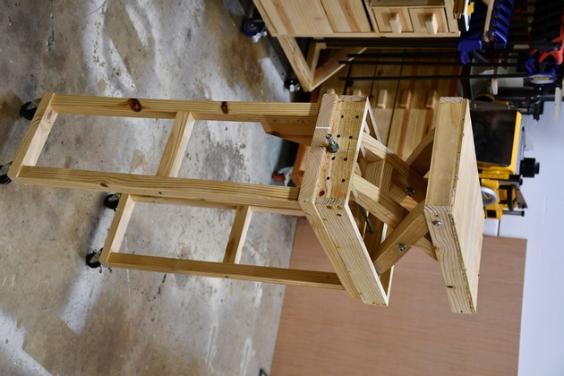
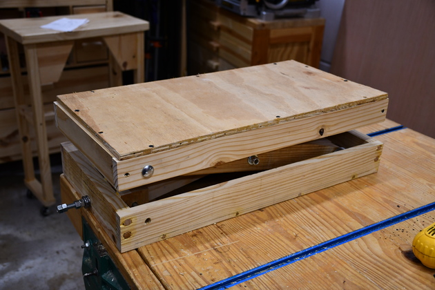
Scissor lift on my workbench cranked half way up. |
|
Different angle of the scissor lift half way up. |
|
Scissor lift almost down. |
|
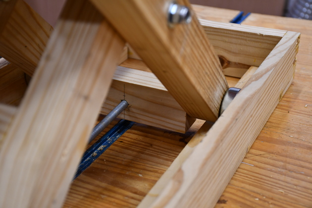
View of the pull block with adjustment rod, skate wheel, pull block, and scissors. |
|
|
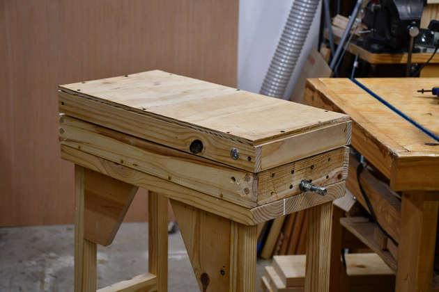
Closed on the work cart. |
|
closer look at the scissor lift on the work cart. |
|
Scissor lift on work cart cranked up to about where it'll be used. |
|
|
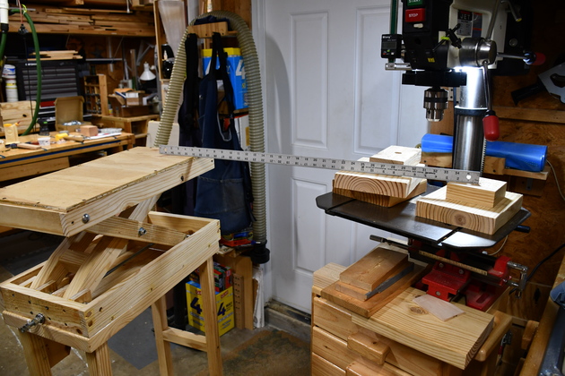
Leveling it with the drill press. I put the straight edge across the level I'll be drilling at, then crank up the scissor lift to match. |
|
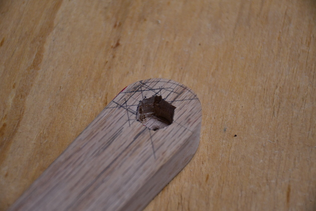
3/4" oak 8" long. Note I've already rounded off the ends and marked the holes. |
|
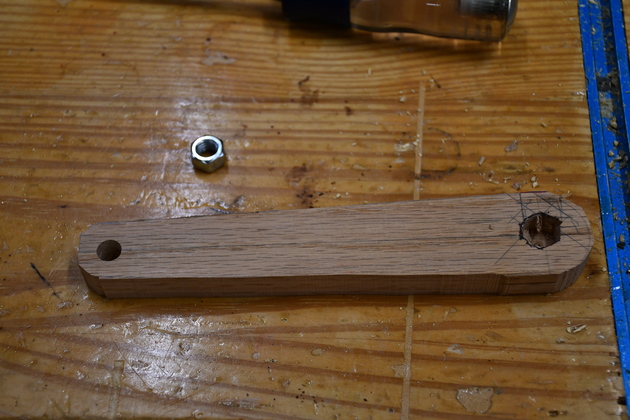
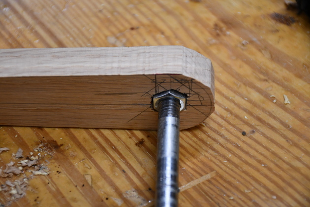
Holes drilled, 3/8" on the left for the handle, and 9/16" on the right for the nut. I've chiseled the corners on the 9/16 hole so it fits a 9/16 nut. |
|
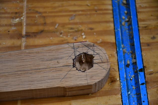
A littel closer look at the 9/167quot; hole being chiseled. |
|
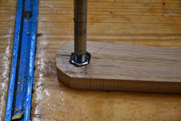
A nut in the 9/16 socket. |
|
This won't have to stand a lot of torque, thank goodness. |
|
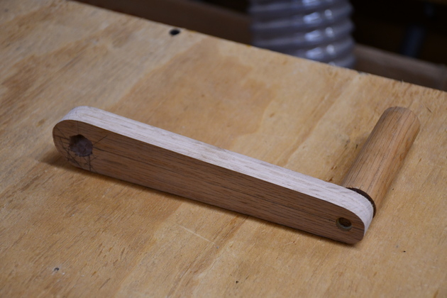
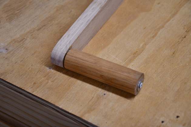
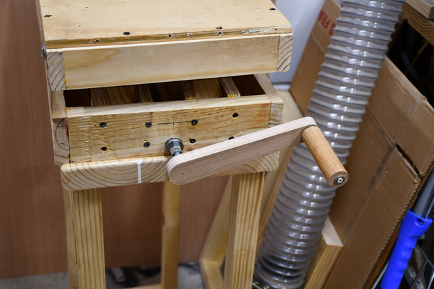
Crank with handle. The handle is a 1" dowel, 3-1/2" long with a 3/8" hole drilled 2" deep from one end (for 5/16" dowel/axle) and another 3/16" 1-1/2" deep (for keeper screw) from the other end. |
|
Crank handle, you can see the wood screw and washer. |
|
Again the 9/16" hex hole. |
|
Crank raising the lift. |
|
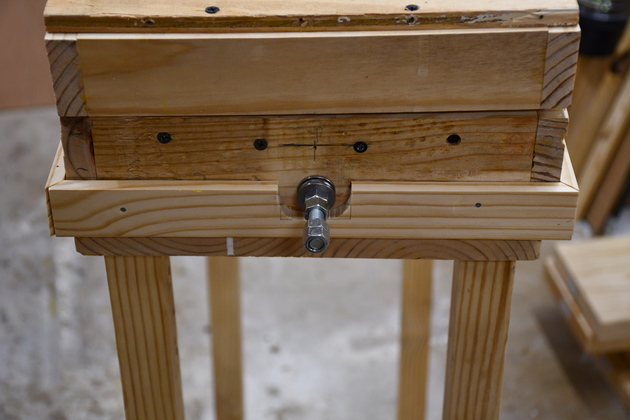
Note the skirt around the bottom, this projects 1/2" down the side of the cart so the lift won't scoot around. |
|
Notch in the skirt for the adjustment screw. Instead of welding the nuts on, just put on a jam nut and aligned them so a deep socket would work. |