|
2" Valve Construction |
|
|
2" Valve Construction |
| 2" Plenum Page |
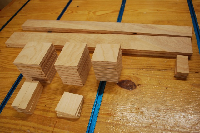
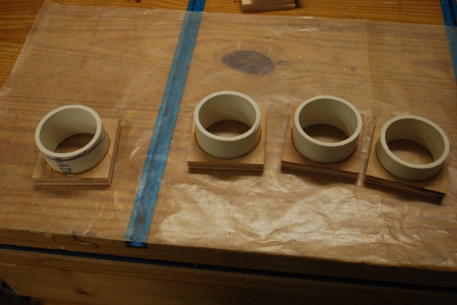
| Birch plywood parts sawed out for plenum and valves. |
|
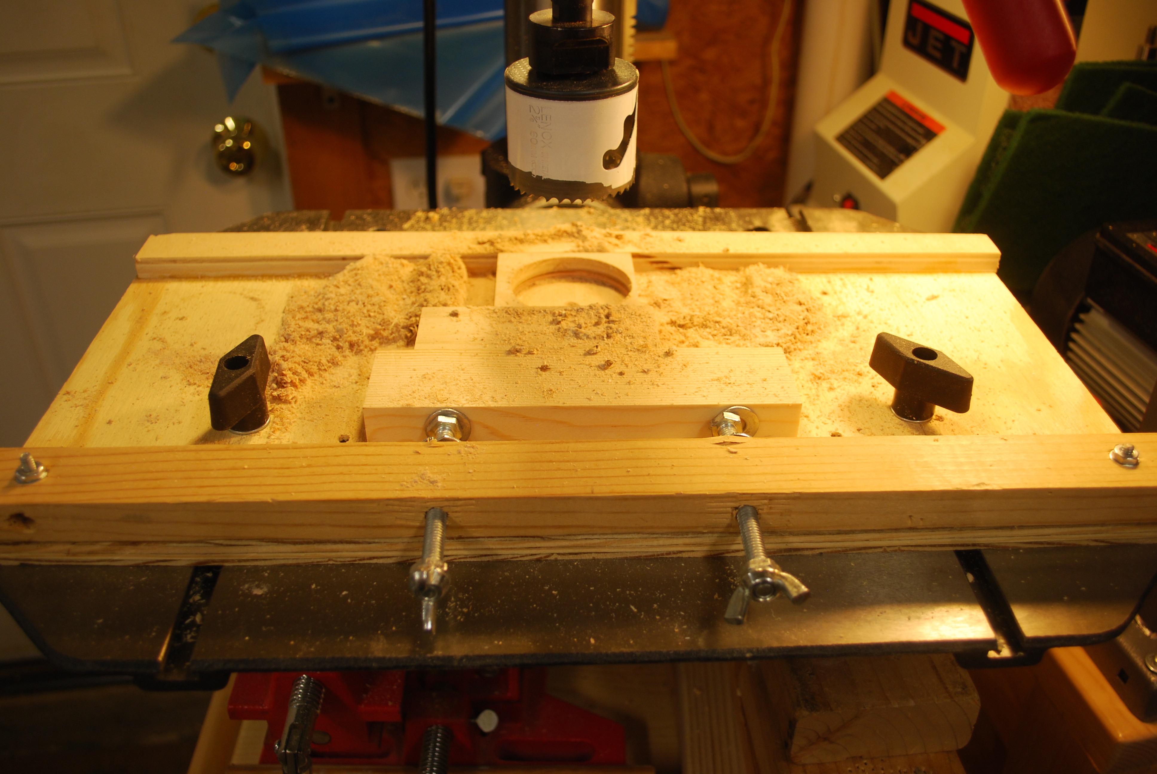
Sawing holes in valve bottoms and tops.
Hole sawing normally places a lot of stress and strain on the work piece, it tends to move when being sawed. This little jig was built for hole sawing on the drill press, it holds the work piece very steady while being hole sawed. It has a 1/2" plywood base and another 1/2&quto; plywood strip glued at the back and a 1x2 attached at the front with two 5/16" hex bolts for adjuting for the size of the work piece. Two 5/16" tee nuts, on the far side of the 1x2, hold the adjustment bolts. Its crude but it works well. |
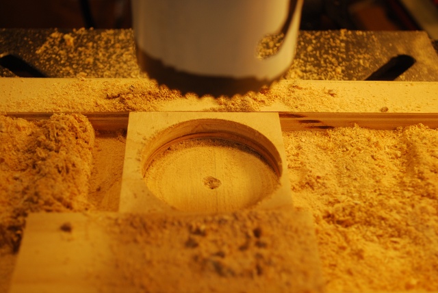
| Closer look at a valve top being sawed, notice the hole is off center. |
| Sanding the valve top and bottom holes smooth. |
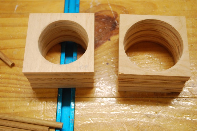
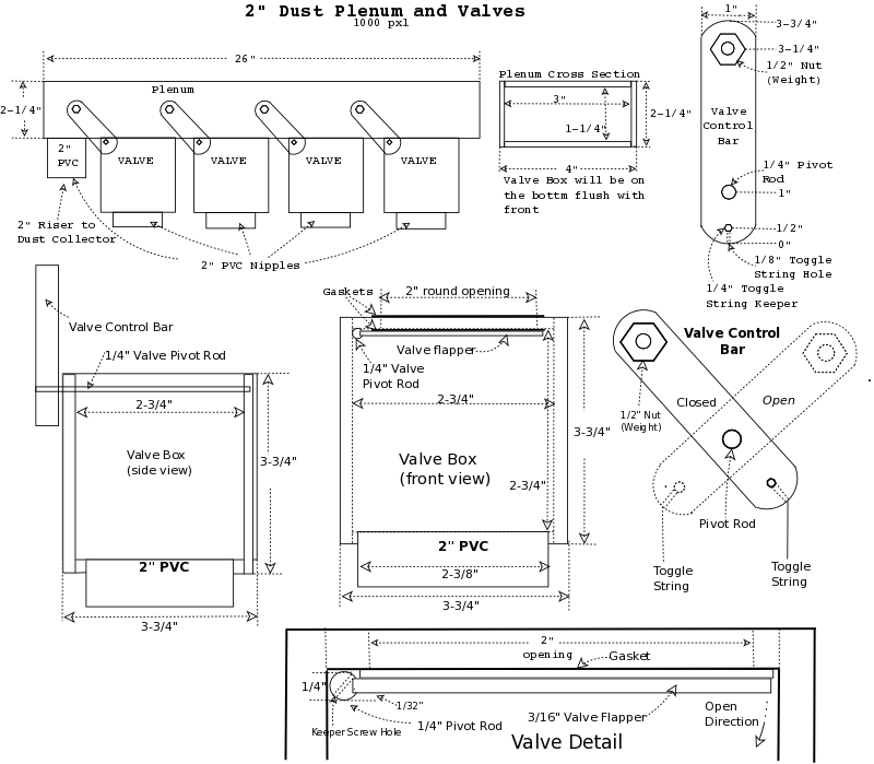
| Valve tops on left and bottoms on the right. Note the valve top's hole is smaller (2" for airflow) and offset to the right to allow clearance for the pivot rod. The valve bottom hole is 2-3/8" for a 27quot; PVC short nipple. |
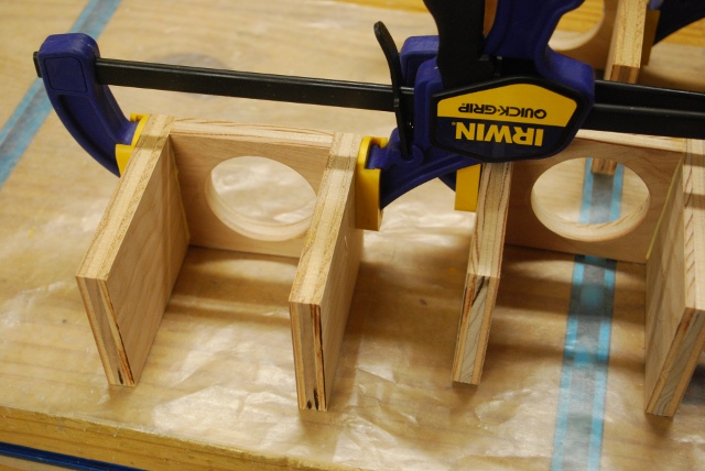
| Sides being glued onto tops. |
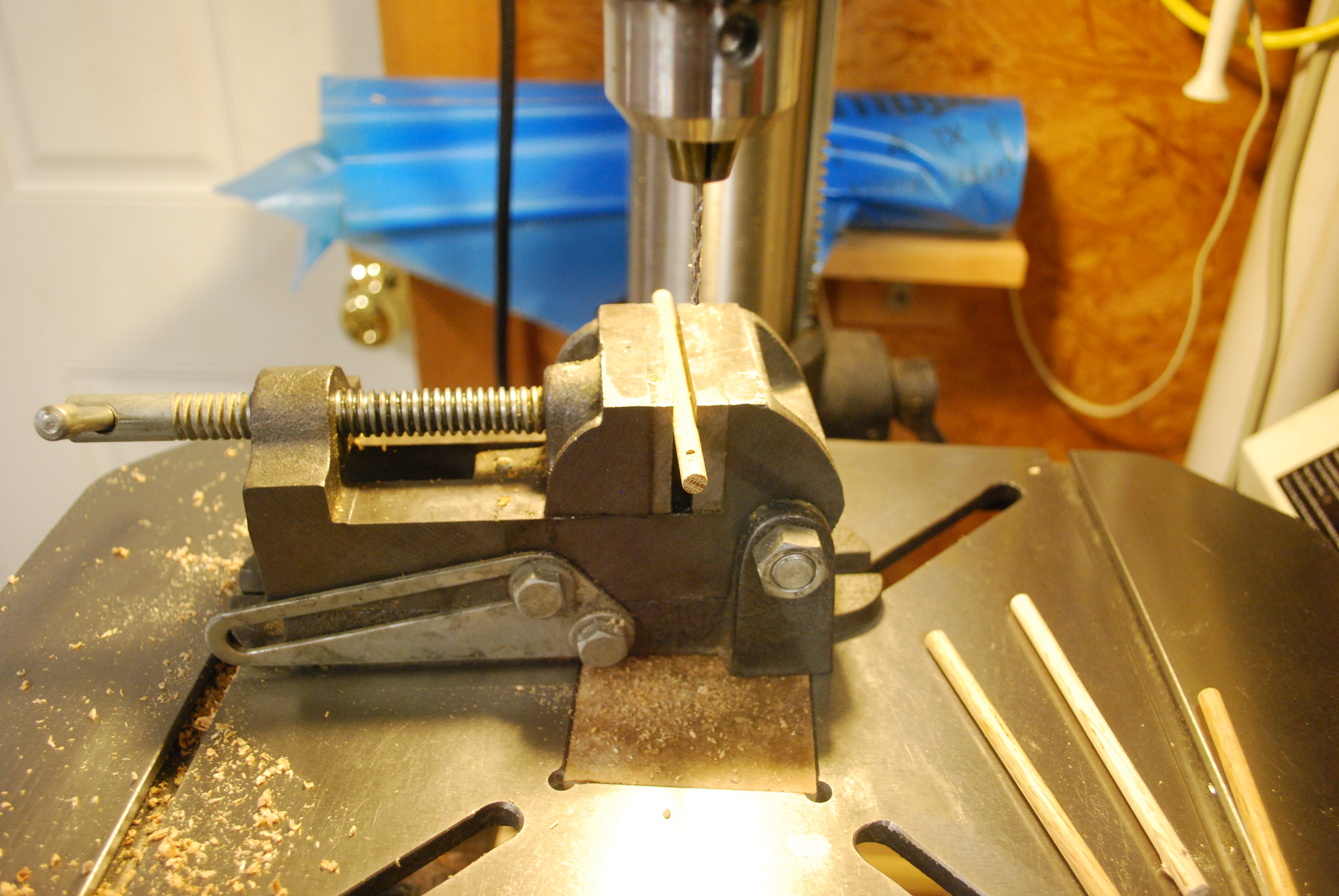
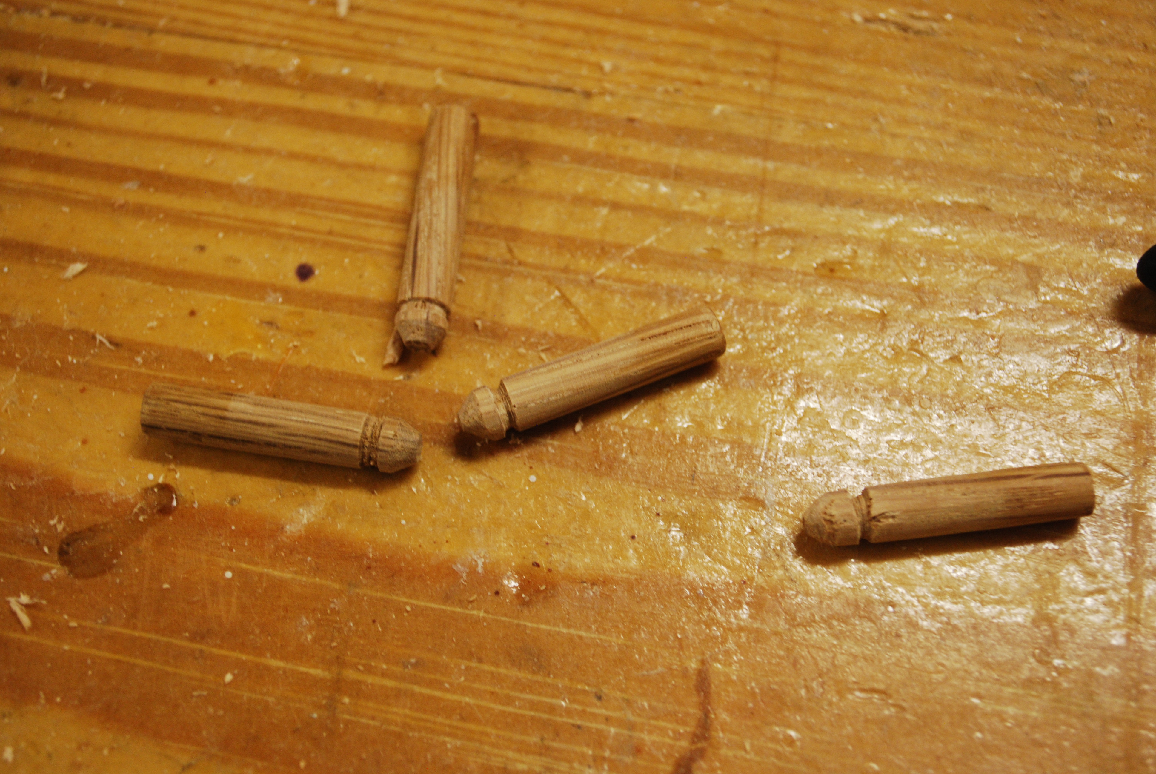
| Screw hole being drilled in pivot rod (1/4" oak dowel) For more pics on how I do this please see pivot rods in the 4" plenum page. |
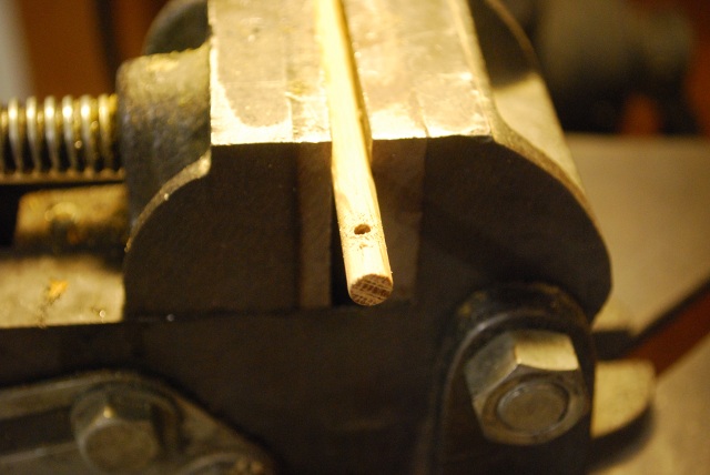
| Closer look at screw hole in valve pivot rod. |
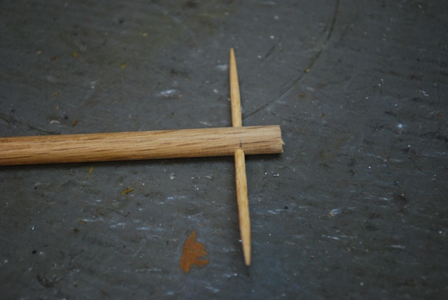
| The screw hole is a pilot hole for the screw but I made it just fit a tootpick to keep it at the correct angle while I'm machining the flat for the valve flapper. Please take a look at the pivot rod machinging on the 4" system. |
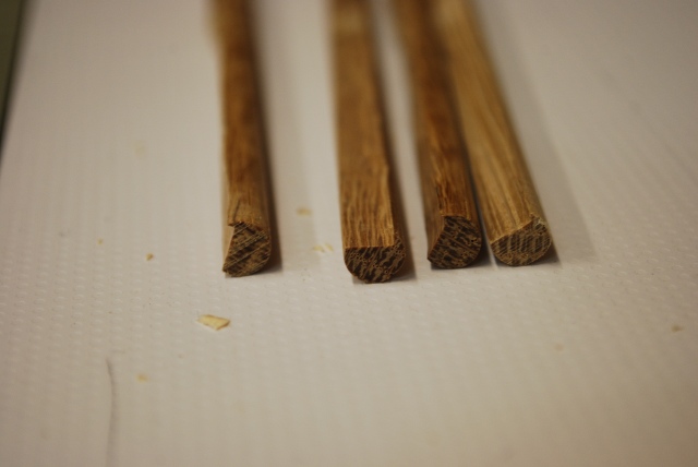
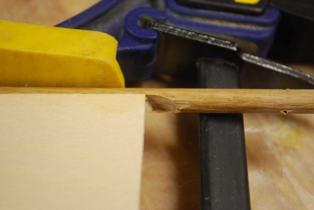
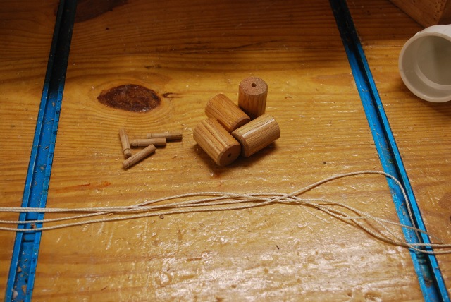
| Pivot rods after machining, you can see the flat machined into them. Also note there is a small ridge on one side of the flat to make sure the valve is offset for the gasket. You have to play with this depending on what kind of self adhesive gasket you get. |
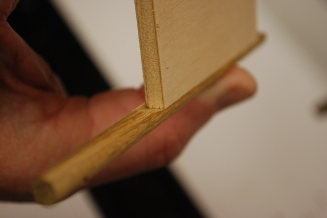
| Here is how the flapper fits into the flat on the pivot rod, the right side should be flush with the side of the pivot rod. |
| Flapper glued to the pivot rod. |
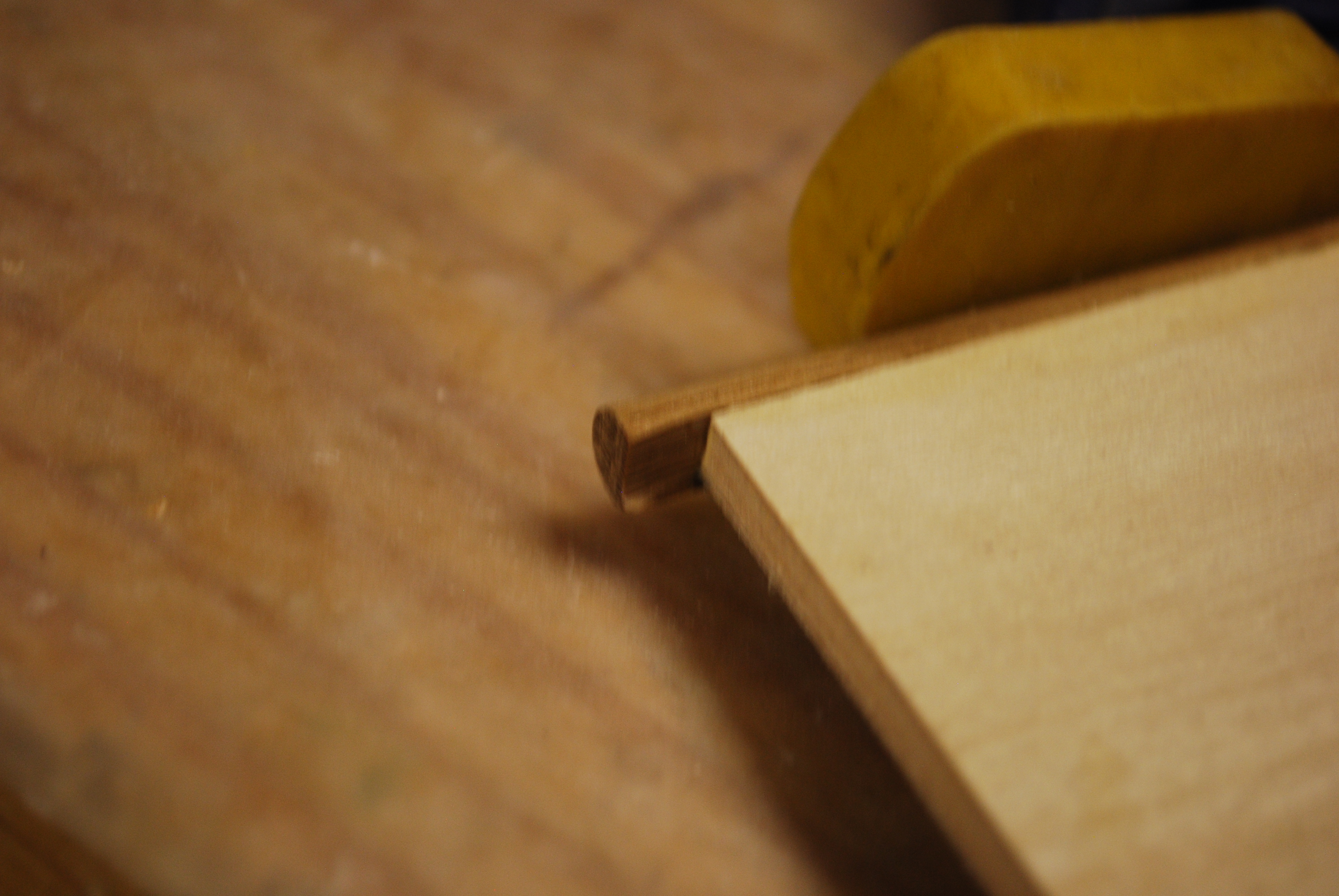
| The far end of the pivot rod has 1/4" to fit into the blind 9/32" hole int the upper left corner of the back of the valve box. |
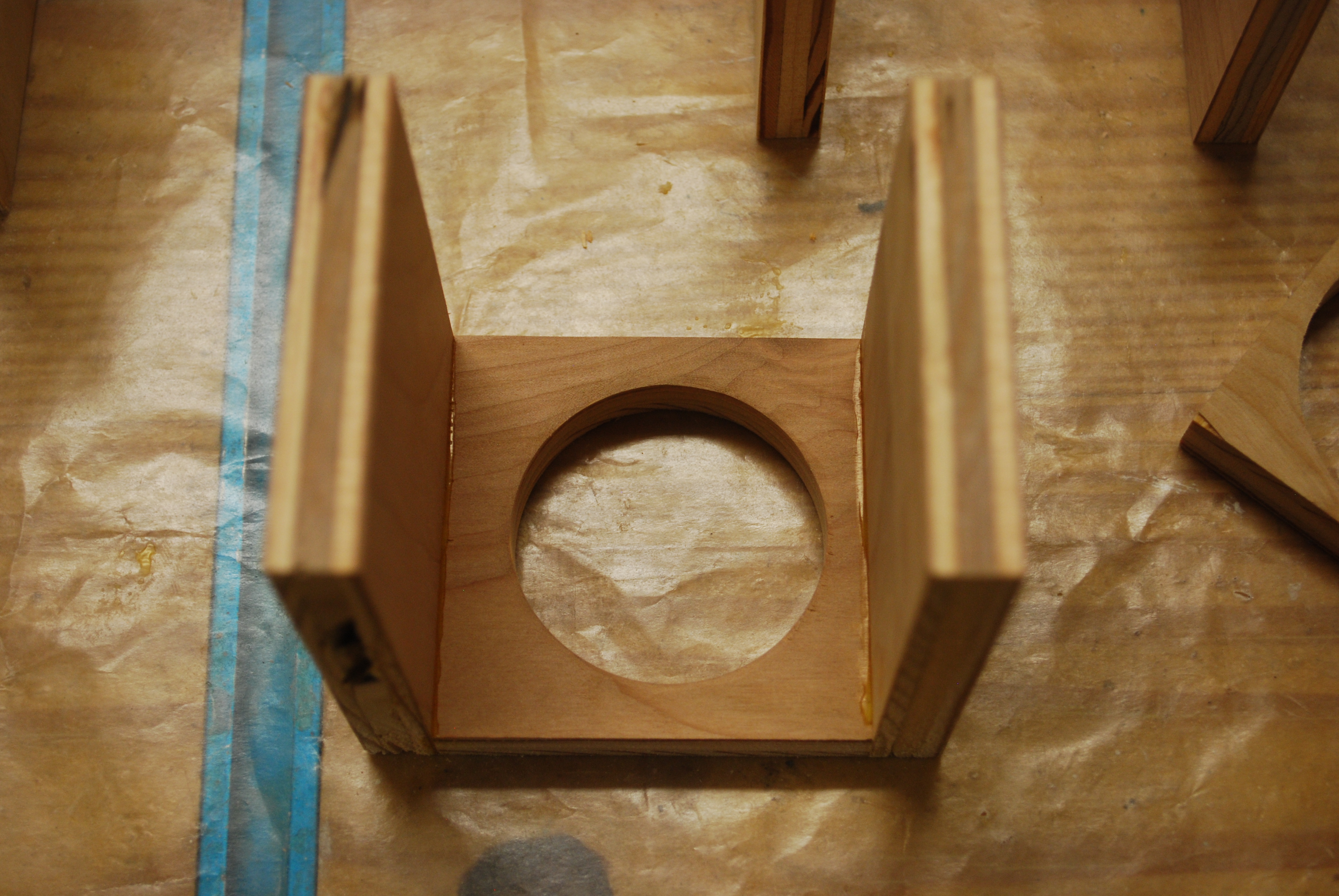
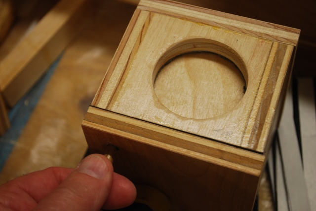
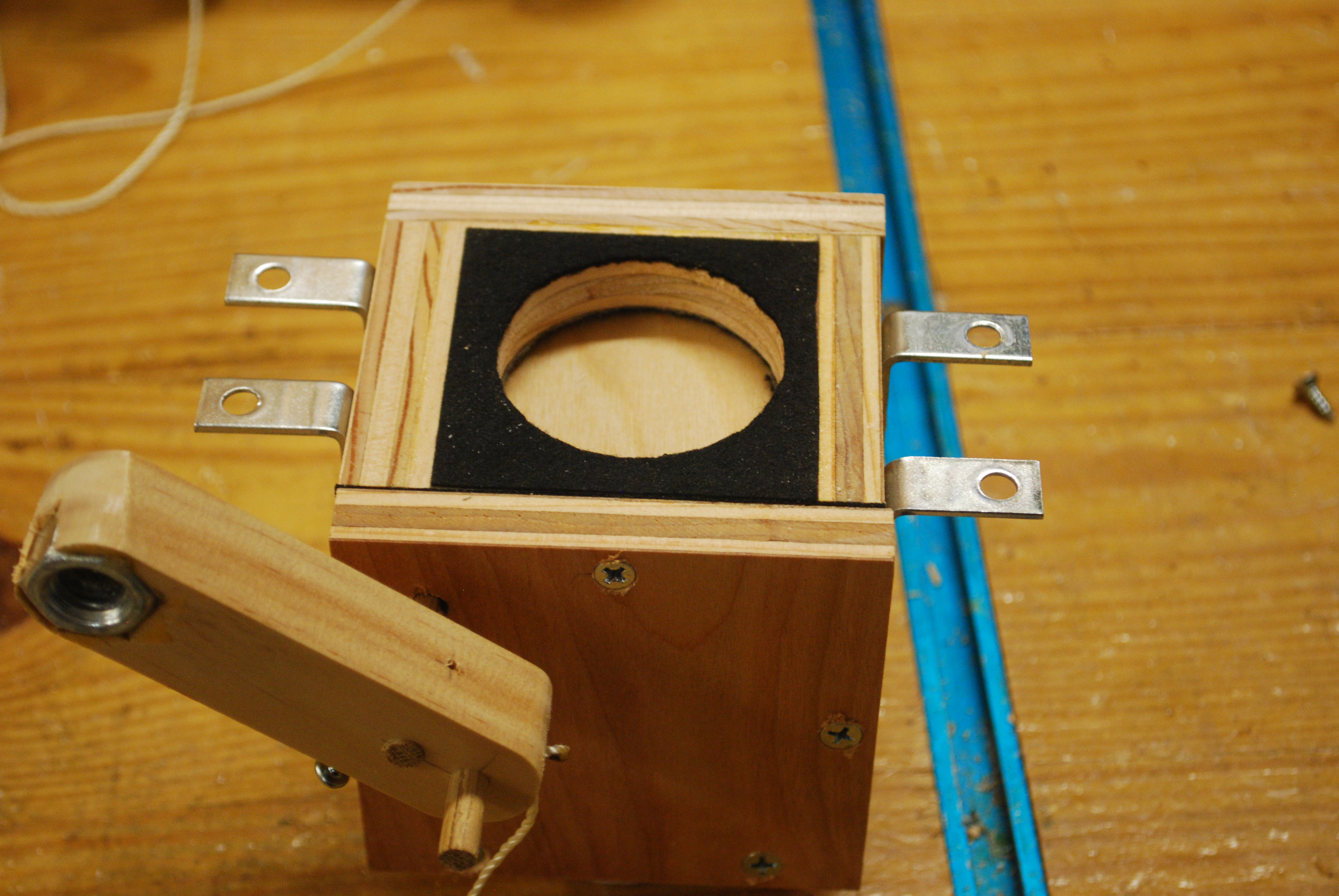
| Looking up into the valve box with the sides on, you can see the 2" hole is offset to the right to allow clearance for the pivot rod. |
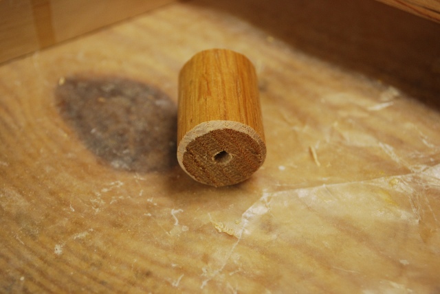
| PVC short nipples being glued into the valve box bottom. The 2-3/8" hole is a good tight fit for the OD of a 2" PVC, I cut the short nipples from a piece of 2" PVC scrap. |
| Gorilla Glue just applied, I put a ring around the bottom end of the short nipple then inserted and twisted it to spread the Gorilla Glue. |
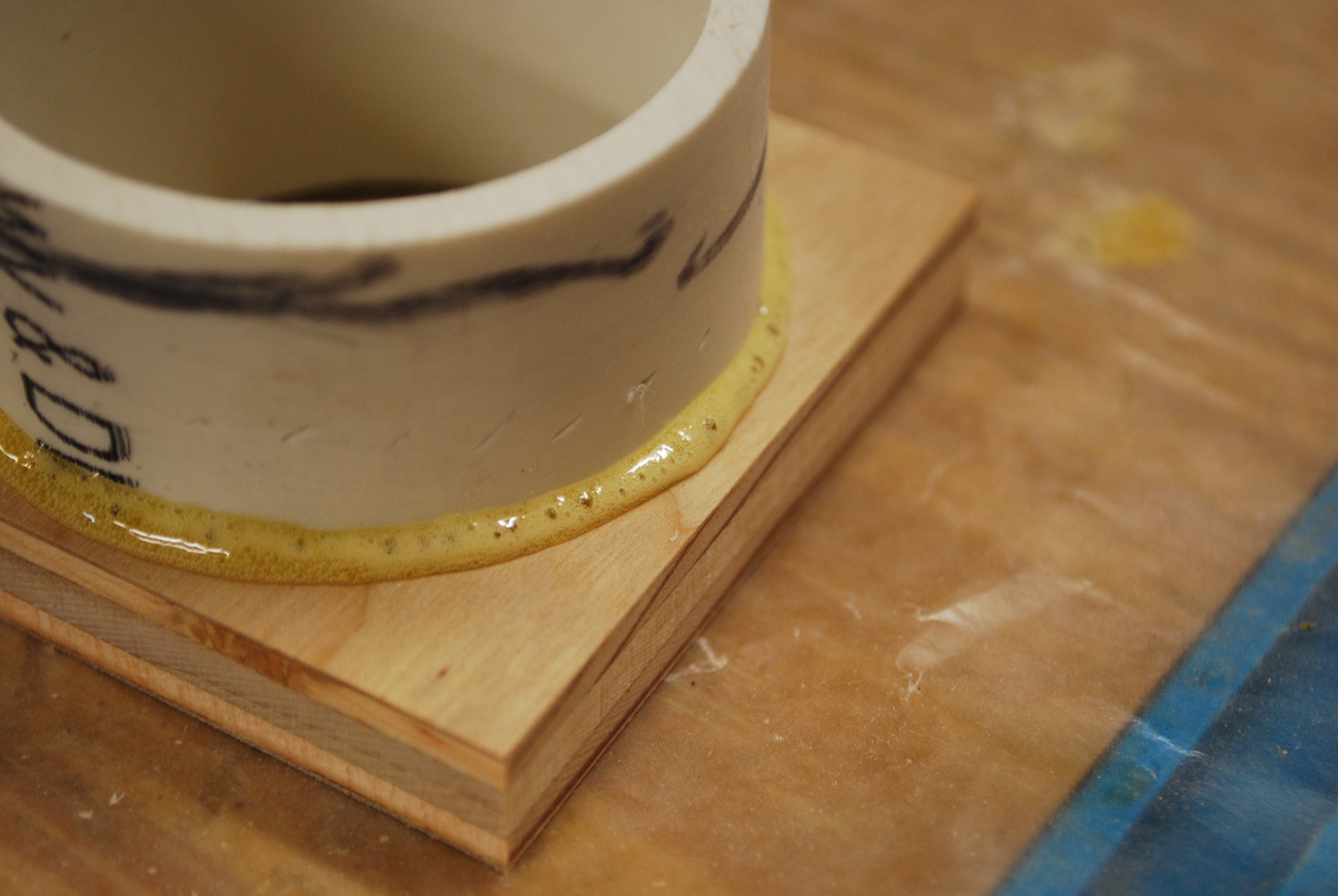
| The Gorilla Glue foaming up, this is why it is so good for making air tight joints, it sticks to everything and foams up a little to fill any voids. |
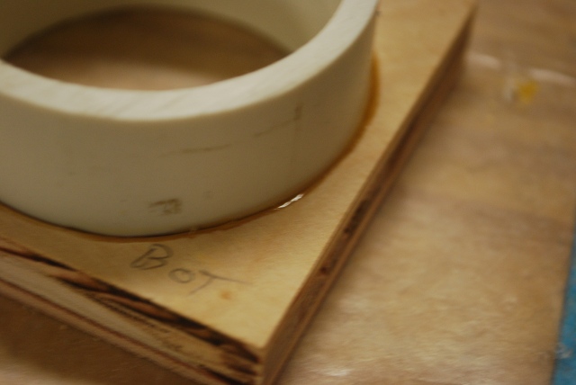
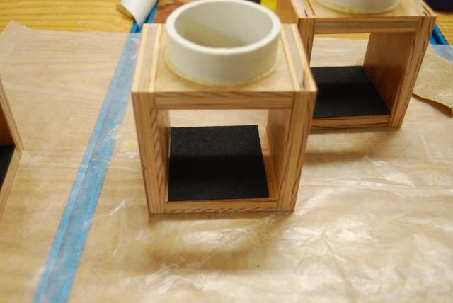
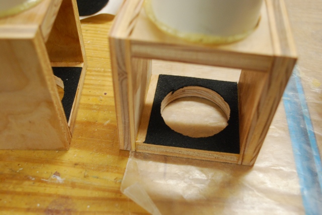
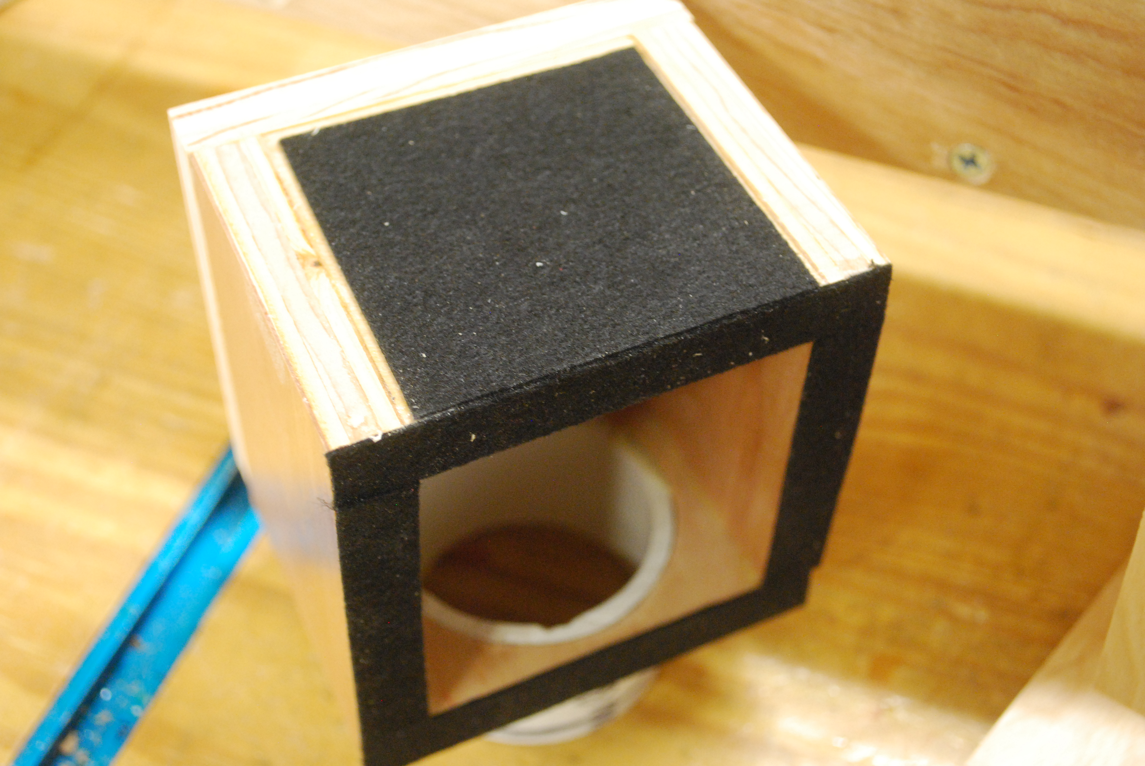
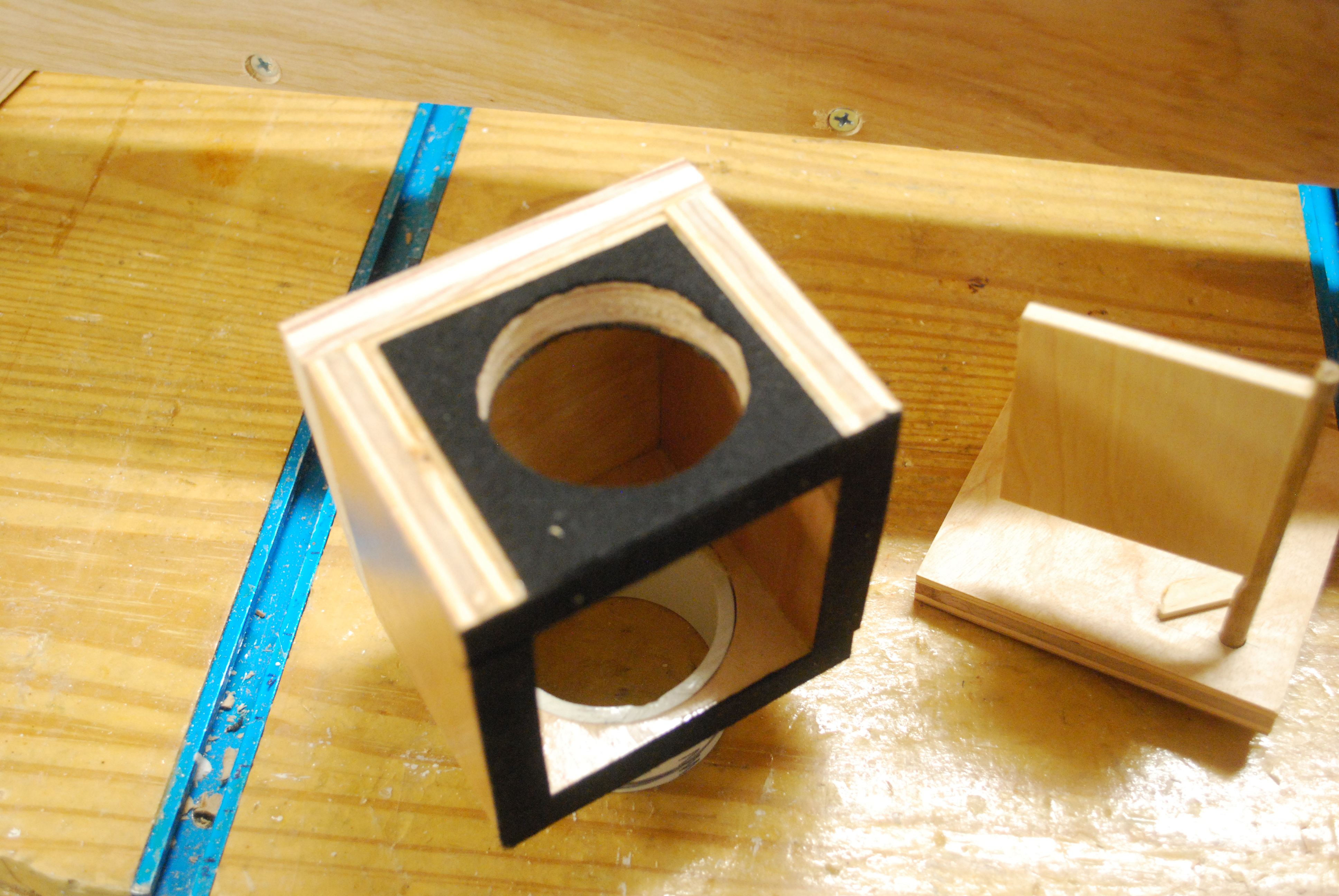
| Valve boxes with bottoms glued on I already painted the inside of the valve box with clear poly. |
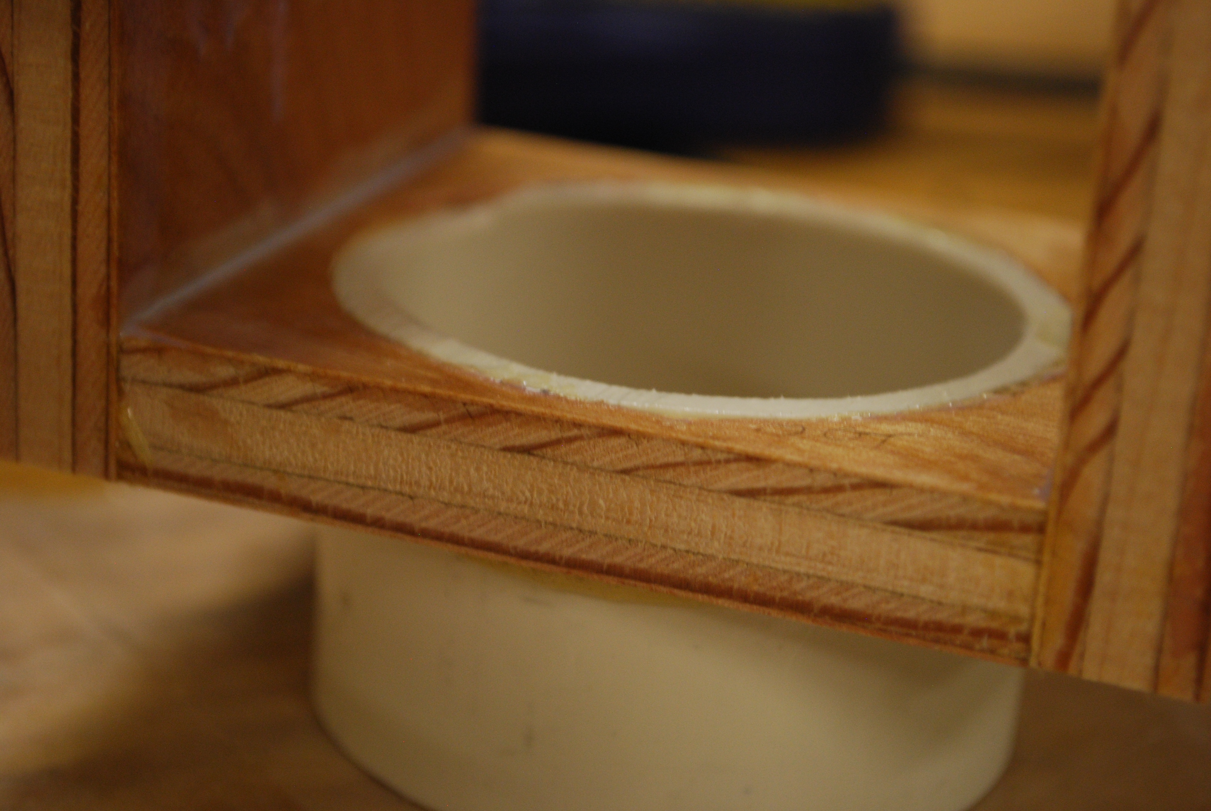
| Note the short PVC nipple is flush with the inside bottom of the valve box. This cuts down on turbulence. |
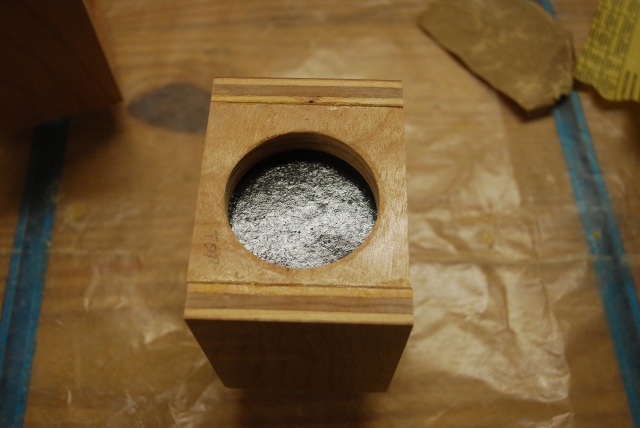
| Self adhesive pad sitting in underside of valve box top. Note the pivot rod clearance on the right. |
| Valve flapper gasket stuck to underside of valve top. There will also be another gasket on top of the top between the valve box and the plenum. |
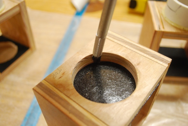
| I'm using an X-Acto Knife to cut out the hole. |
| Hole cut in gasket material. |
| Valve flapper fitting. The valve flapper must move very freely, here I'm holding it closed by the pivot rod. In the next pic I release the pivot rod and the valve should fall open. |
| Valve flapper falls completely open when I release the pivot rod. You have to test this at all future stages of the valve assembly until you install the valve control rod. Then the weight will prevent it completely opening when upside down. In normal oeration, the valve control bar holds the valve open or shut, the last position you toggeled it to. |
| Valve flappers and pivot rods ready to paint. |
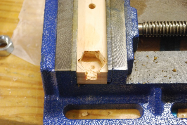
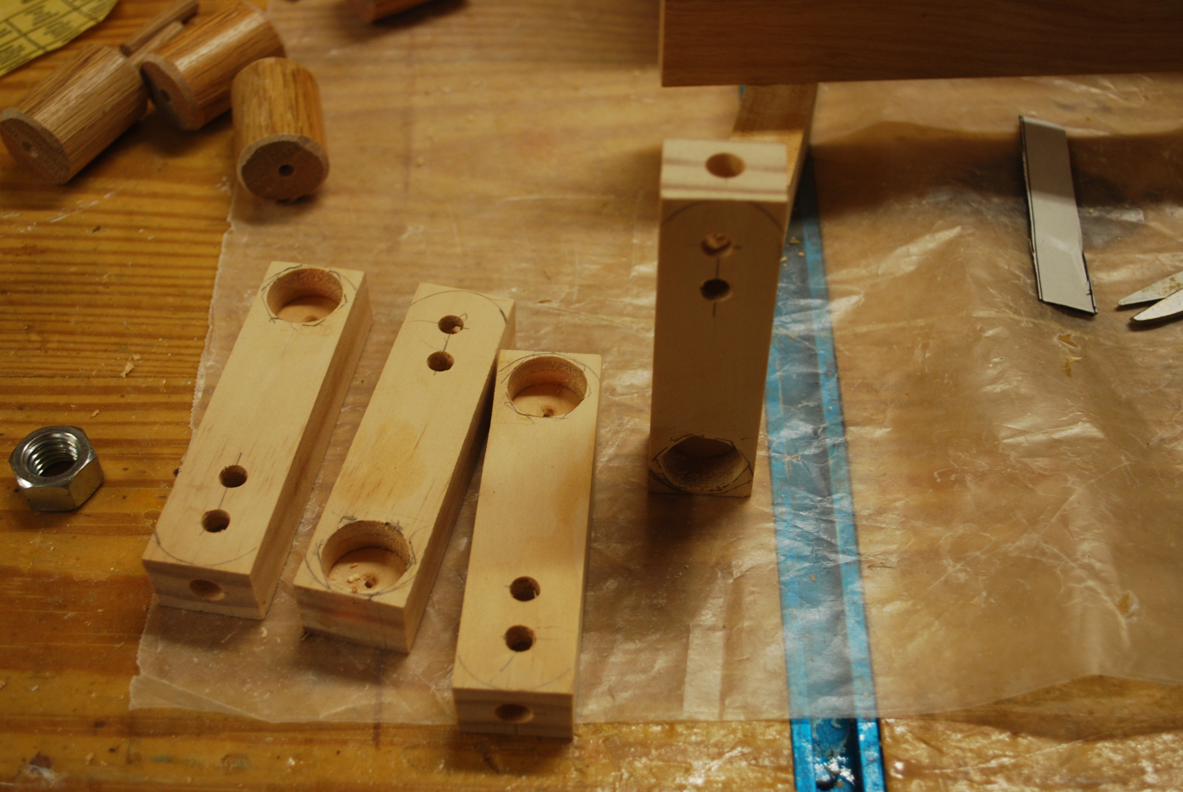
| Valve control bar, round counter bore has had 6 corners chiseled in to make a Hex for the nut weight. The round counter bore is 3/4" in diameter, and 3/8" deep. |
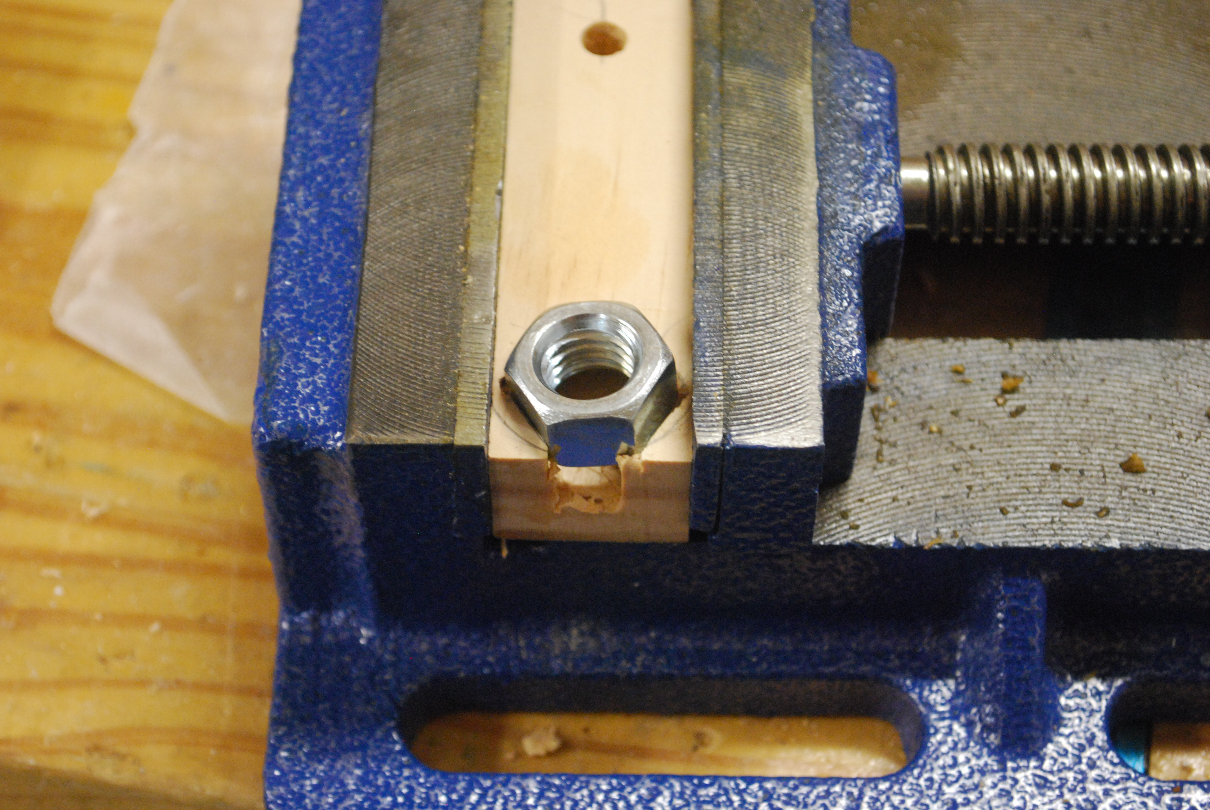
| Control bar weight test fit of the 1/2" nut (weight). |
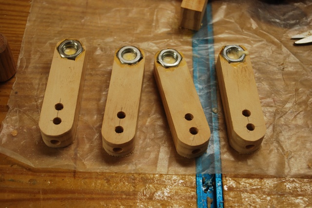
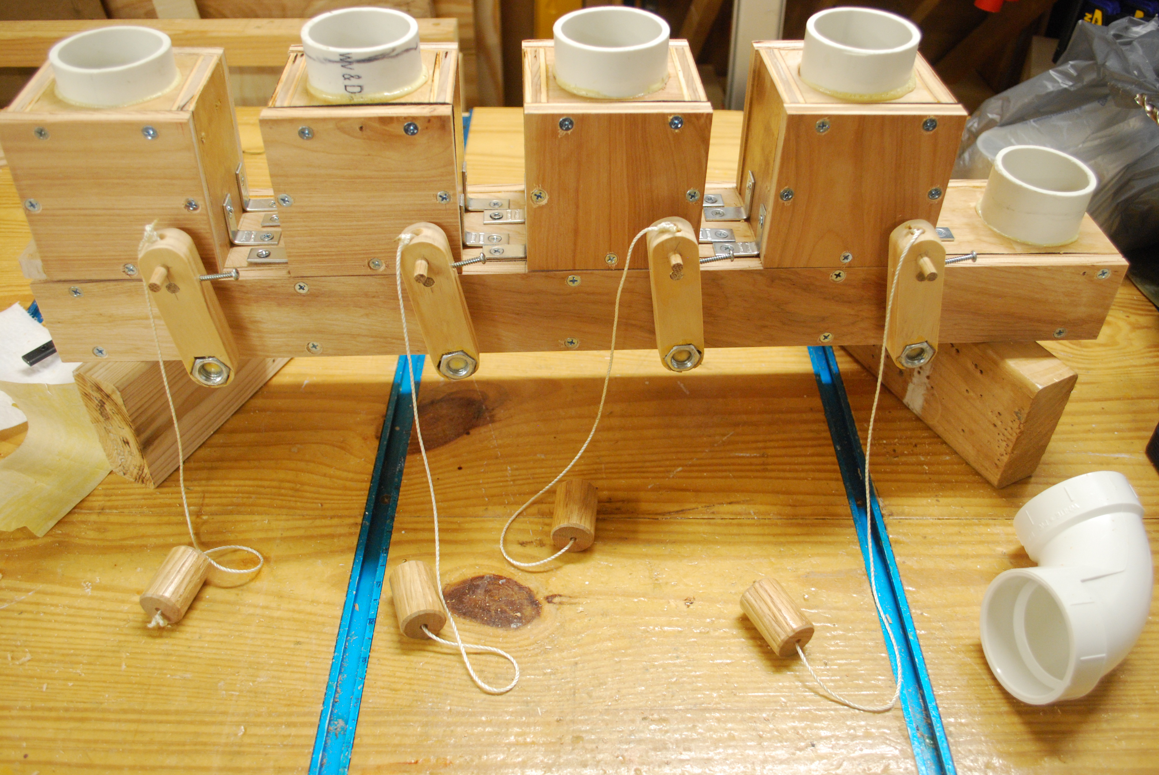
| All the control bars with weight being glued in, all holes drilled. Note the two holes in the upward face near us, the nearest hole is for the toggle string keeper, the farther hole is for the pivot rod. The hole in ths end is for the toggle string. The pivot rod and keeper holes are 1/4" through holes, the toggle string hole in the end, is 5/16". Note I have rounded the corners with the bandsaw and sanded them. I have glue these in with Titebond, I just realized this would have been a good place to use Gorilla Glue. |
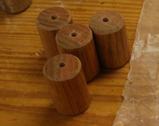
| Valve knobs painted, chamfered, and drilled. These knobs go on the end of the toggle string. |
| CLoser look at valve knob. |
| Gasket stuck over 2" hole on top of valve. This gasket seals the valve box to plenum's bottom. You can also see the valve box's front cover gasket. |
| 2" hole cut out in valve box gasket. The valve box front cover with the flapper and pivot rod are laying to the right of the valve box. |
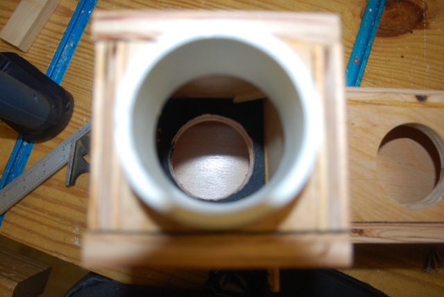
| Looking up through PVC connector and the open valve into the plenum. You can see the valve flapper on the right against the side of the valve box and it's gasket on the underside top of the valve box. |
| Knobs, keepers and toggle strings ready to assemble. |
| Closer look at the toggle string keepers. THe notch is where the string will fit, the pointed end helps push the keeper through the loop in the top of the toggle string. |
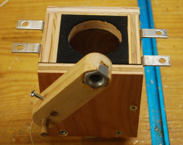
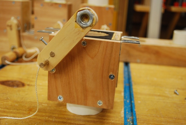
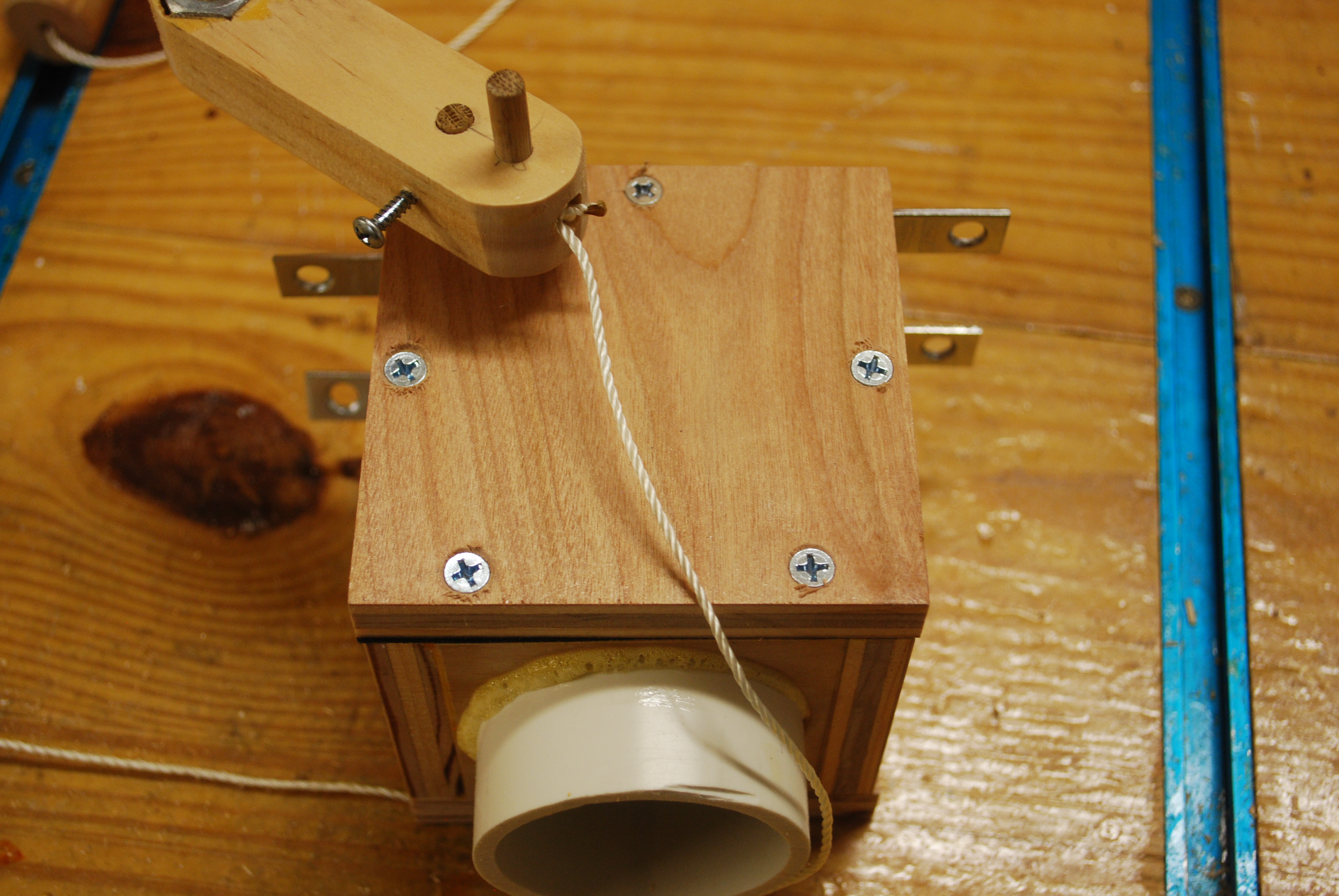
| Finished valve, open, painted, with control rod, toggle string, and mounting brackets. The valve should fall completely open when you move the control rod just past center to the right. |
| Finished valve, closed, the valve should completely close when you move the control rod just past center to the left. |
|
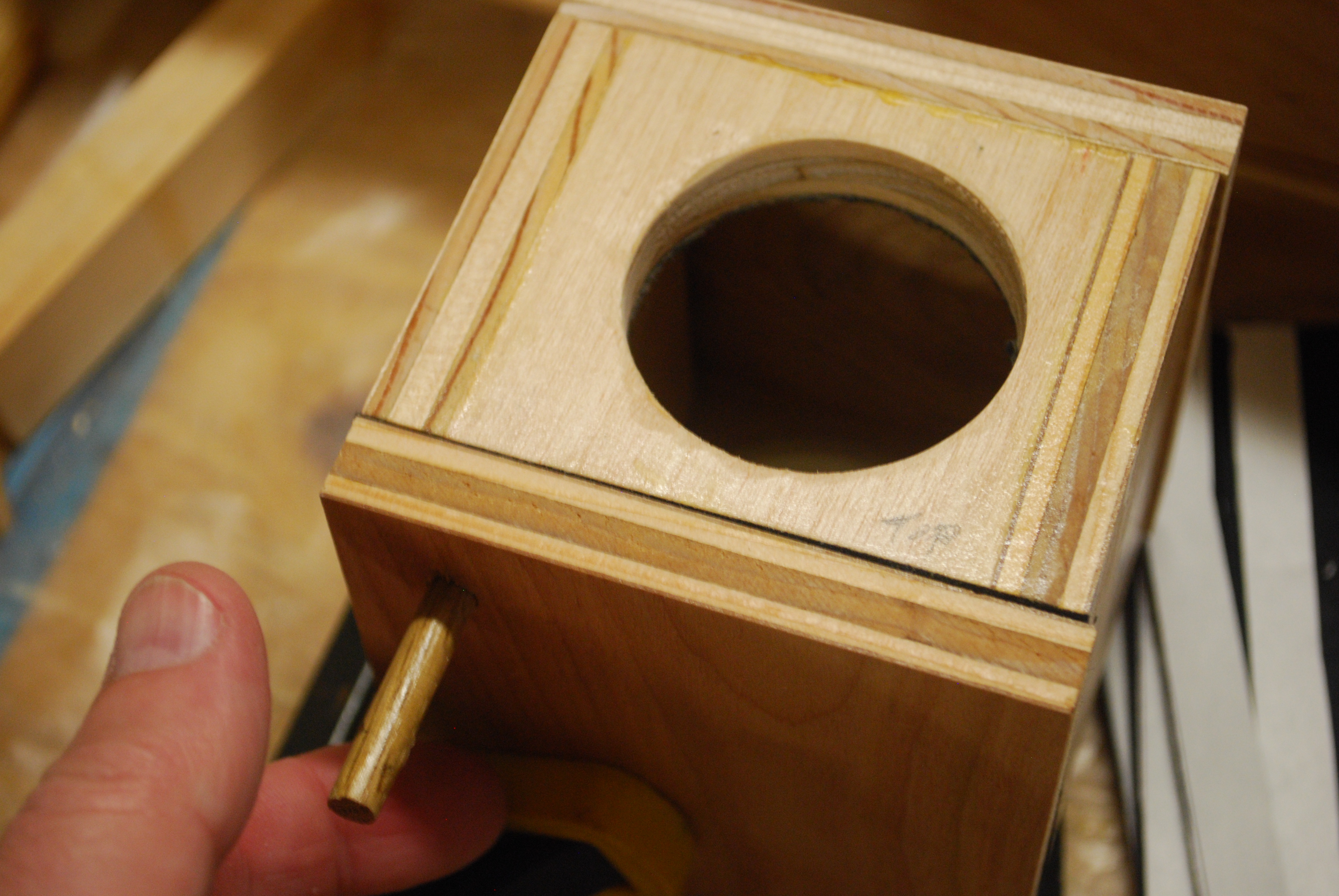
| Front of finished valve, note the screws holding the front on, control bar, end of the pivot rod and the toggle string keeper. |
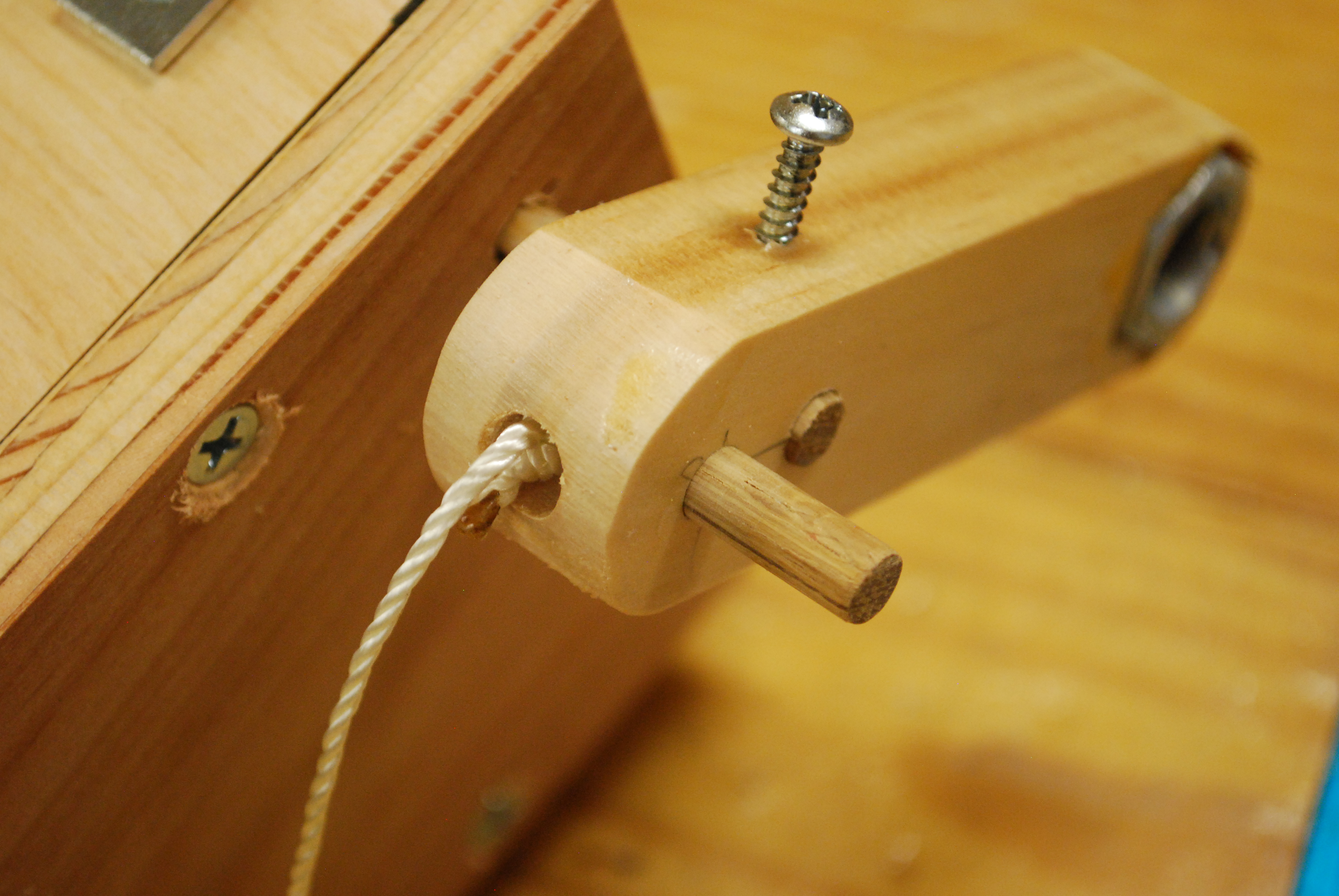
| Lower end of control bar, note toggle string and keeper. This time, I simply tied a bowline in the top end of the toggle string, instead of a slip knot, I thought it would be easier to remove if I needed to. |
| view looking upward at a valve. |
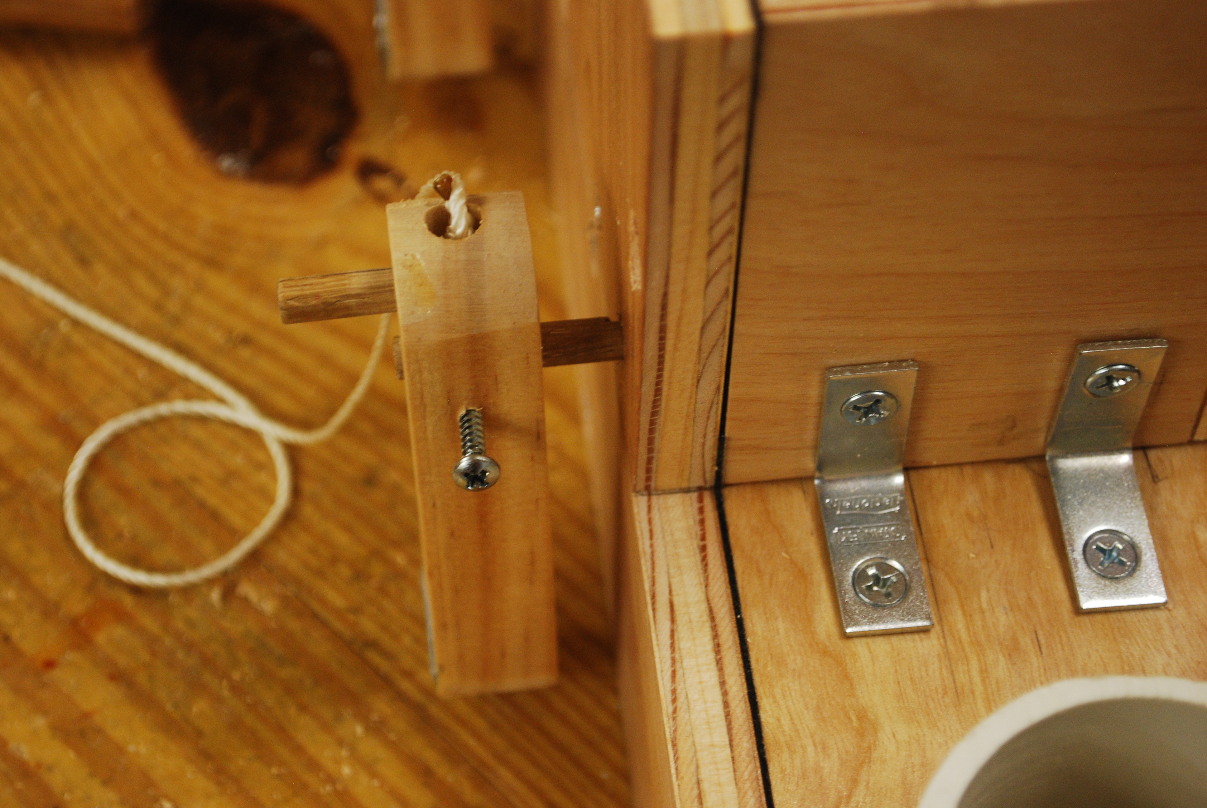
| Valve mounted on plenum note the front of the valve must be flush with the front of the plenum. You can also see the two mounting brackets on this side of the valve. |
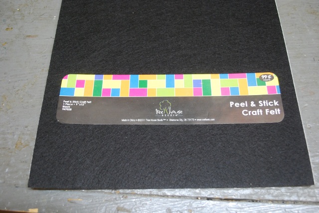
| Here is one of the pieces of "Peel & Stick" I bought at Hobby Lobby, its 9 X 12". |
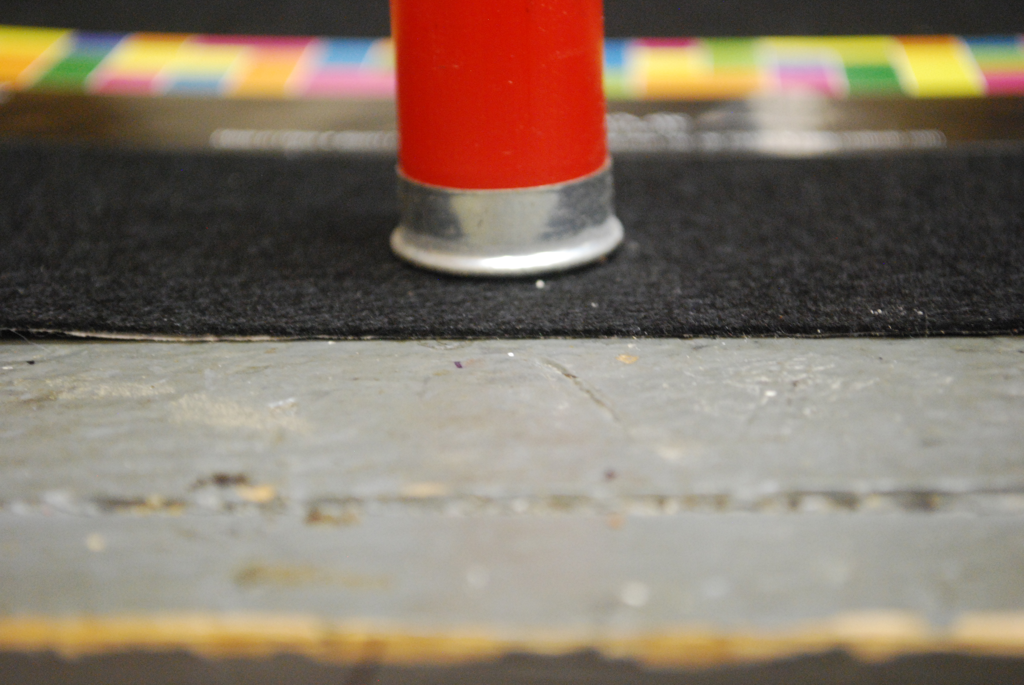
| With a 12 ga shell for reference, the felt is about 1/32" thick. |
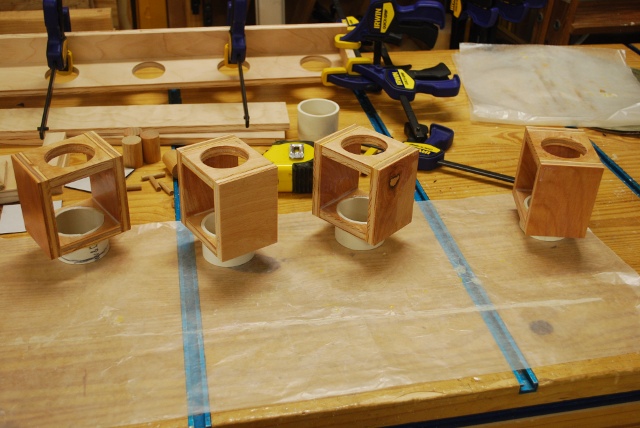
| Plenum and valves ready to install. Since the valves are upside down they're not open or closed hence the control bars aren't at a 45° angle. The slight deflection of the valve control bar is caused by the weight of the valve flapper inside the valve box and the weight in the control bar. |