| 
| 
| 
|
|
|
|
|
|
As part of the Dust Collector Automation (DustAuto) project, in order to have a completely automated system, I wanted to include the Dust Detector. I redesigned the original dust detector so that it would talk to the DustAuto system via hardware RS232. The DustAuto system will request a dust depth once per second, the Dust Detector 2 will get the depth and send the information back to the DustAuto system. The dust auto system will display the dust depth on it's data terminal and decide when to shut down the DC blower. The dust depth transmissions from the Dust Detector will need to have 3 consecutive readings at or below 8" before the system will be placed in "Dust Halt" mode, and shutdown the DC blower (if it is running). A cancel, entered on the data terminal, will reset the system to IDLE mode and it will restart probing the Isensors for an auto start.
Since I no longer need 12 Volts, the Dust Detector could also be powered from the DustAuto system, thus removing the 12 Volt power adapter, 3 terminal requlator, and the transistor driver for the alert device. And since I will now display the dust height on the data terminal, I don't need a power indicator on the Dust Detector.
The new dust detector consists of a Nano, wire, and connectors, I decided to use one of the Nano breakout boards that I used to prototype the original. I'm also going to change the connectors on the sensor to 4 wire JST.
Note: I added a small enclosure around the sensor, inside the dust bin, to keep dust accumulation from obscuring the dust pile in the bottom. It consists of an open ended frame of 3/16" plywood around the sensor. Pics coming soon. It does decrease false readings, in general appears more stable.
|
|
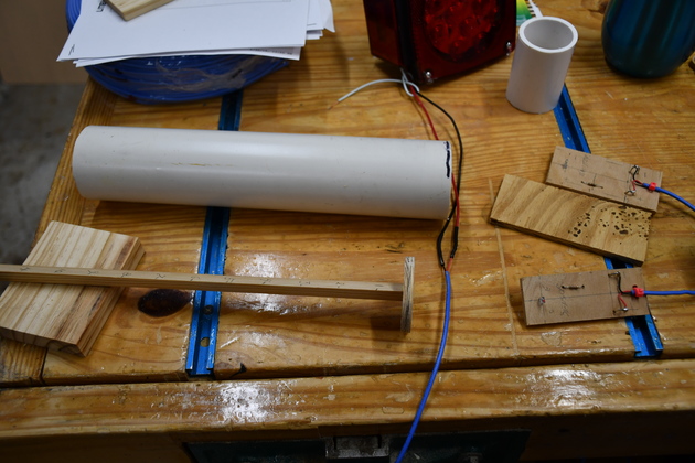
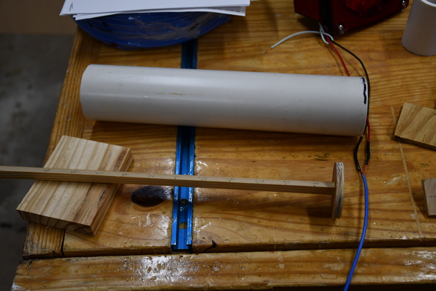
Test lash up. The dust sensor is mounted on a screw terminal Nano breakout board which, in turn is mounted on the cabinet base. These Nano Breakout boards are about 3$ or 4$ each, and available from Amazon and they are very handy. I used two 4 wire JST connectors, 1 maile and 1 female, one to connect comm and power from the DustAuto system, the other is trig, echo, and power for the HC-SR04. |
|
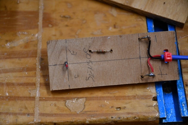
The DustAuto processor close up also mounted on a screw terminal Nano breakout board. When I did this, the normal system board is installed in the shop (I didn't want to unplug and replug all those wires). One nice thing about using the hardware RS-232 interface for the data terminal is you can also use the IDE to control the system when you need to test. Note the resistor, pulls down the analog input (Zin) so it doesn't try to open valves and start the DC, not that anything would happen, but I needed it to stay in IDLE state unless I change it with the IDE's serial monitor which it thinks is the Nano data terminal. |
|
|
Close look at the dust detector. |
|
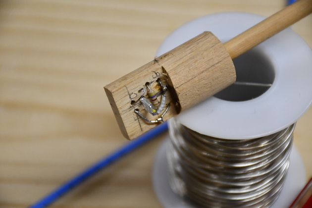
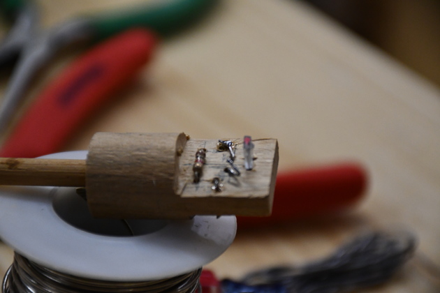
HC-SR04 ultrasonic sensor circuit side view. |
|
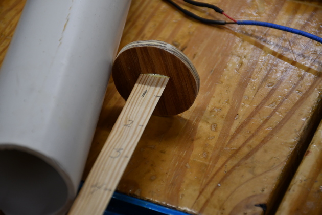
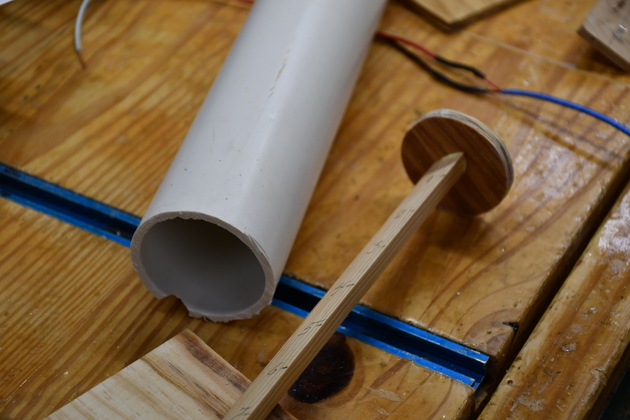
HC-SR04 mounted on a test block. |
|
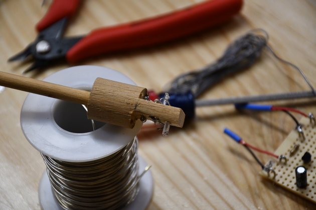
Different perspective on the ultrasonic sensor. |
|
Another look at the Dust Detector and it's test HC-SR04 sensor. The JST connector and 4 wire cable |
|
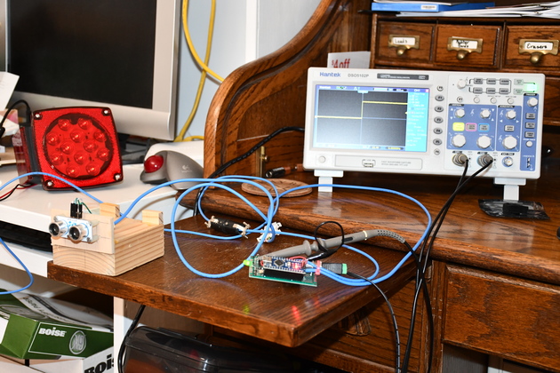
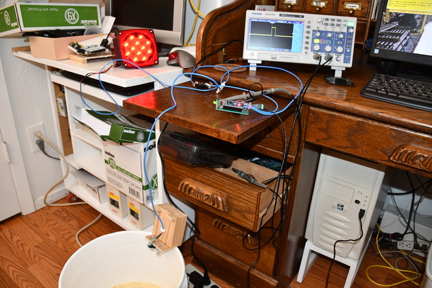
Sensor return on the scope looking at the wall behind me. You can see the ultra sonic sensor (HC-SR04) on the pull-out shelf to the left, it is looking at a wall about 6' away. |
|
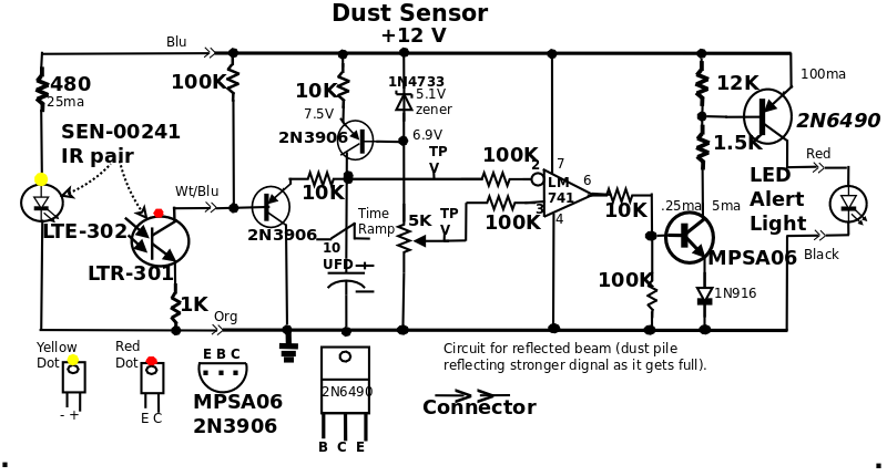
Sensor return on the scope looking at the sawdust in the bucket. You'll note the big red light is on (this was with the old dust detector but same sensor and Nano). |

|
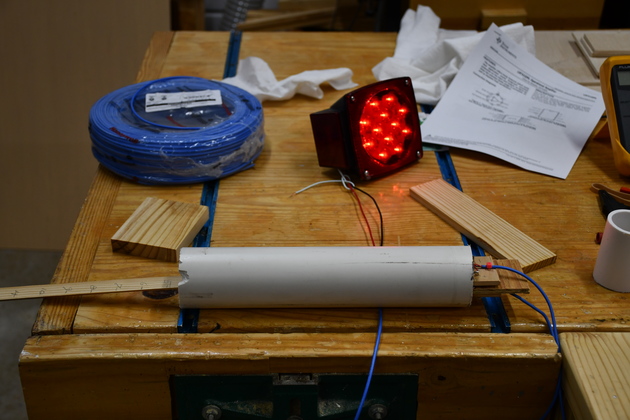
The dust detector2 installed under the filter shelf. The 4 wire flat cable goes to the Dust Collector control box, it carries power to the Dust Detector and RS232 to the control box. |
|
|
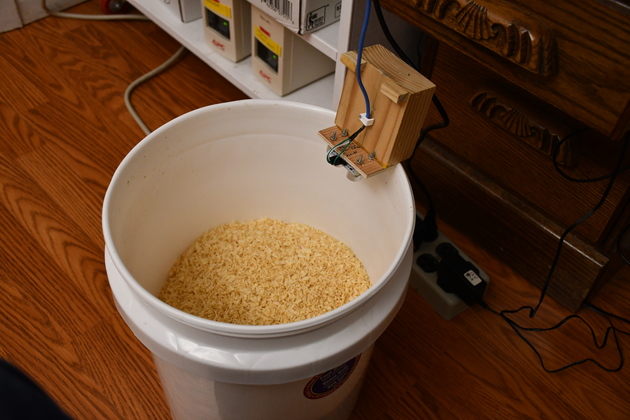
The top of the dust bin (30 gal. trash can) you can see the sensor wire (blue cable). |

|
Closer look at the dust bin top with sensor mounted. You can see the top of the dust bin plug. Yes, thats a small nail being used as a pin to keep the dust bin plug from being sucked into the bin. |

|
|