When I added the 6" cyclone to the large dust collection system, I added a 33 gal garbage can for a dust bin.
I had no way to determine when this new dust bin is full.
Oneida has a dust sensor for about $150 and since I know how, I decided to build a dust sensor of my own.
When I started looking for parts and I thought one of the more difficult things would be the indicator, until I found an LED boat trailer tail light for $18 at Walmart.
Note if you use an incandescent tail light you need to worry about total current.
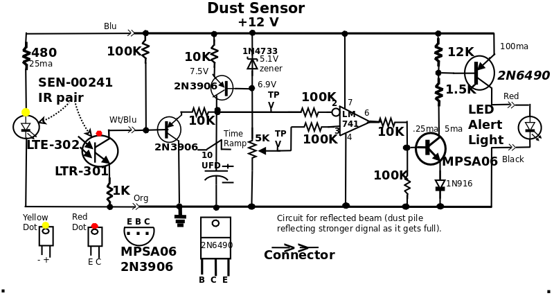
I guessed at the current drawn by the taillight and the resistance of the photodiode and scratched out a circuit.
You could even use a 12 Volt siren (as long as it's draw is less than 1A) for alerting on bin full.
I used a 12V, 1 Amp switching (not magnetic) wall wart.
I went to Mouser.com for transistors, power supply, diodes, etc.
All the parts I bought were reading right to left (cheapest) and in stock (at the time), so far I'm out $39 total.
In most cases you can use any PNP, NPN, transistors (being mindful of reverse breakdown and forward current on the output PNP), zener diode, switching diode.
You could probably just buy assortments of transistors, resistors, diodes, etc.
After I received the LED tail light I measured it's current draw and was surprised at it's 100 ma (brake light only).
I'm working on the photo emitter/sensor so I don't know how much light I'll receive inside the dust bin.
When they get here I'll test them and fix the circuit.
One consideration is will IR see the dust particles or right through them???
The device Oneida uses (Banner QS18VP6D) says it uses IR (450 nm) but there is a lot of things called IR out there.
Just what does wood look like to IR, how opaque or translucent??
The emitter / sensor pair I bought (Sparkfun SEN-00241, $1.95) work at 940nm, very low frequency (long wavelength) for light, hopefully the sawdust will be opaque to that wavelength.
Some testing is decidedly in the near future.
There are at least two ways of checking the dust level,
first direct: emitter on one side sensor on the other aimed at each other, when the beam is broken, hopefully, dust is in the way.
After testing I found I could reflect enough IR off wood to make the alert light turn on and off, so...
Another thought: in watching the videos of the Oneida Dust Detector in action, I noticed the warning light flashes a whole lot while dust is flowing around in the dust bin.
I assume this is because of dust clumps or particles randomly reflecting back IR while the dust is swirling around in the dust bin.
This bugs me!
It occurs to me that it needs a low pass filter of some kind so it only comes on when there is actual dust close to it or blocking the beam!!!
I'm guessing that a low pass filter of .5 to 1 sec would stop a lot of this flickering.
So I thought of a constant current charging a cap, and the charge being knocked down by "beam detects" from the sensor.
I'm using an op-amp (LM741 I bought at Fry's) as a differentiator, to switch when the ramp crosses the set level.
When the cap charge hits a certain level the warning light comes on.
The reflecting circuit will actually discharge the cap when the dust gets full so I'm gonna put a resistor in to slow down the discharge.
I added a pot (potentiometer, variable resistor) so I can set the voltage level which turns the alert light on and off.
After testing I determined that reflection would work with these sensors so I combined them on a single unit.
I thought that mounting in the top of the dust bin would mostly keep them out of harms way.
The dust bin is under vacuum pressure so I thought I would build a sensor unit that would fit snugly into a round hole.
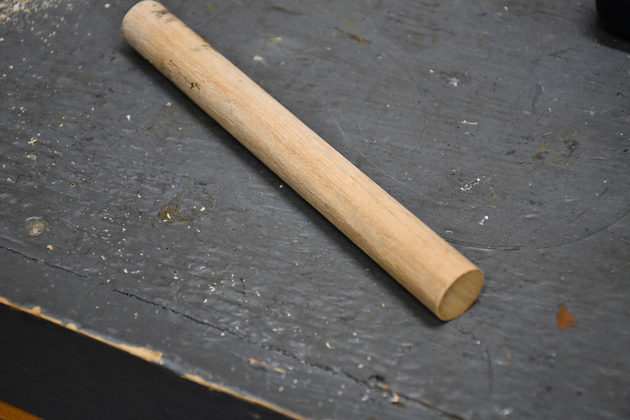
So I got a piece of 3/4" dowel rod and machined off a 1/4" flat, on each side.
The flats would be 3/4" long, enough to hold each sensor, and it's associated resistor.
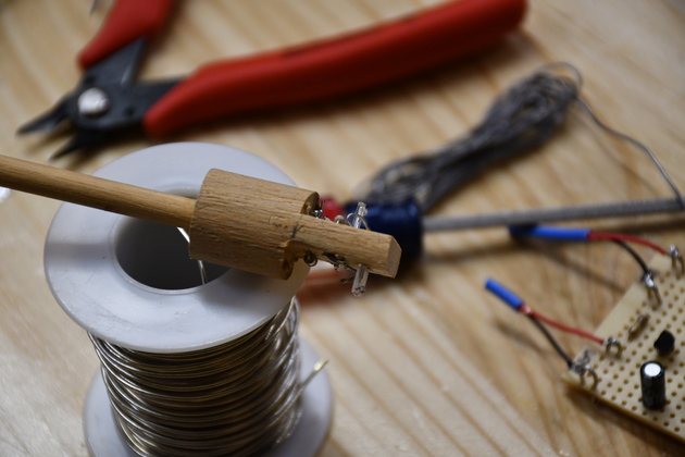
I glued a short piece of 1/4" dowel rod into the back of the sensor for a handle and a place to anchor the wire.
Light wavelengths (part of the electromagnetic spectrum):
IR: 1mm - 700nm.
Visible: 700nm - 400nm.
Please see the wavelength page.
 Control Board
|
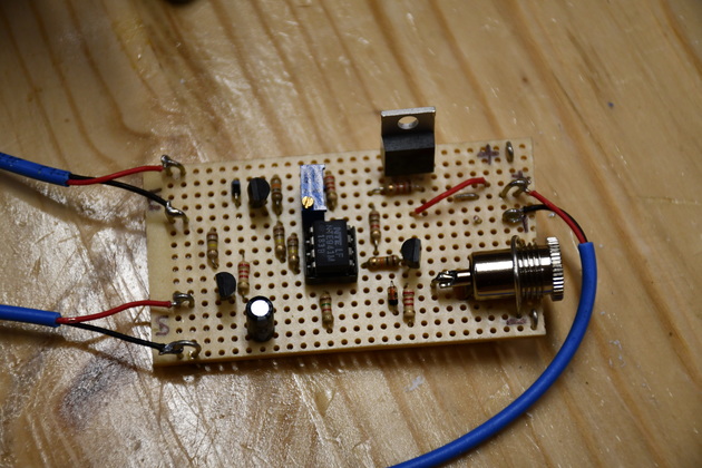
The controller.
The two cables on the left go tothe emitter (top), and sensor (bot) boards.
|
|
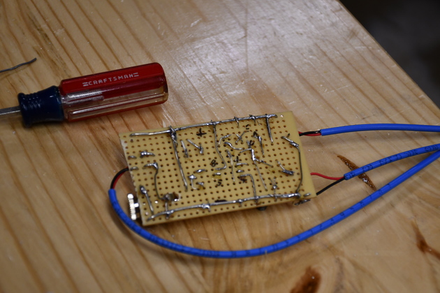
The bottom of the control board, I just soldered it together.
|
Test Sensor
|
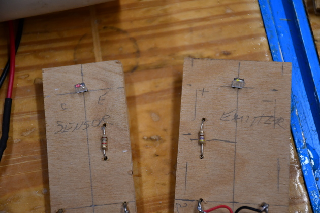
I initially built the sensor and emitter on seperate boards so I could test beam breaking and reflection.
Sensor board on left, emitter on the right.
After testing the circuit and determining that reflection would work, I combined the sensor/emitter into a single unit.
|
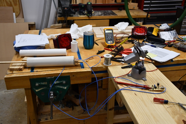
Testing
|
I used my roll around shop table and the workbench to do the soldering on.
This the way I built the BCD clock.
|
|
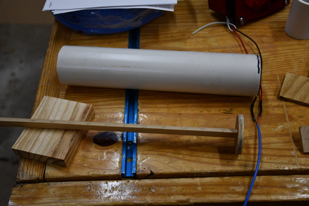
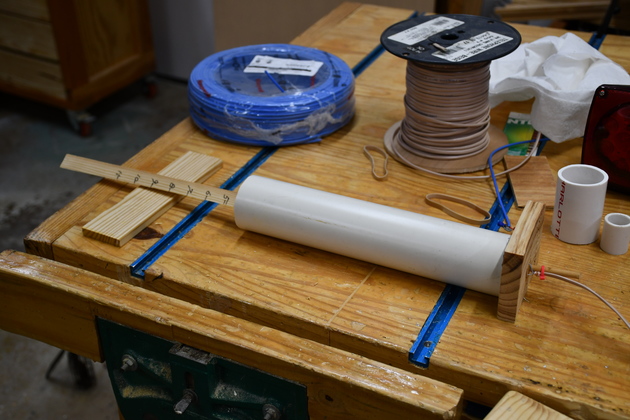
I used this piece of 2" PVC as a dark chamber to test the sensor and depth setting.
I cut a round piece of wood 2" in diameter and glued it to the end of a wooden rod.
I use the wooden rod with it's disk as a plunger with the sensor at the right end.
When the disk gets the set distance from the sensor enough IR is reflected back to activate the warning light.
|
|
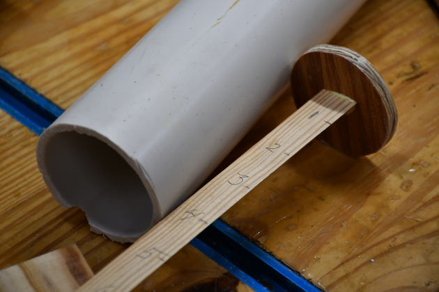
The end I insert the plunger.
You can just barely see the marks, every inch, to tell me how far in the disk is.
|
|
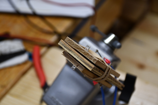
This is the sensor/emitter boards rubber banded together to test reflection.
|
|
The plunger inserted into the tube, you can see the two sensor/emitter boards protruding from the right end.
Note the light is on.
|
|
I back the plunger out a little and the light goes out.
|
|
The disk is 4 inches from this end the light is out.
|
|
At about 4-1/2" the light is on, dust too high.
|
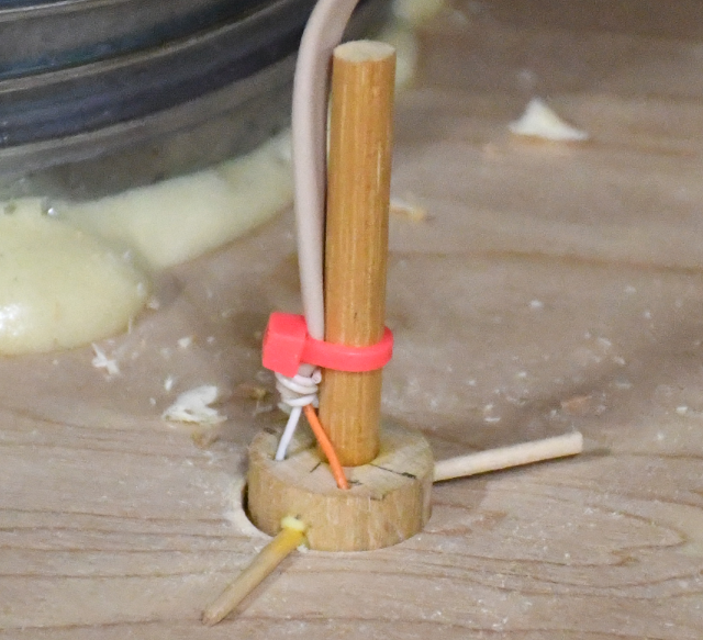
Final Sensor
|
3/4" dowel, I'm going to make a single sensor that I can insert through the wooden top of the dust bin.
|
|
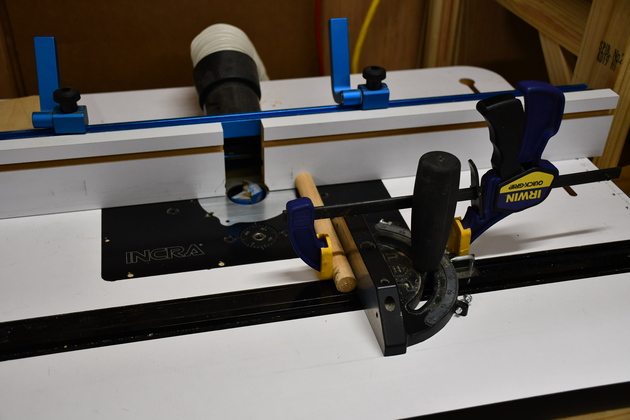
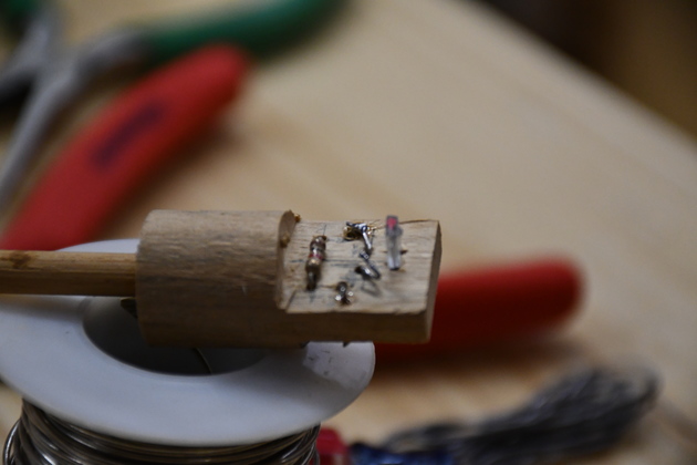
Here I'm using the router table to machine two flats on the end of the sensor.
The dowel is 3/4" diameter, I will machine off 1/4" from each side leaving a 1/4" thick by 3/4" long slab in the center to hold the components.
|
|
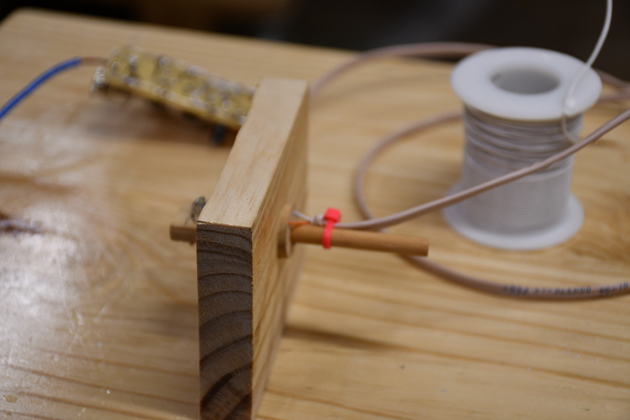
Here is the final sensor, you can see the sensor on one side and the emitter on the other.
Hopefully, the sensor won't see any direct IR from the emitter.
You can even see part of the control board in the background.
|
|
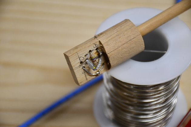
The top of the emitter side, you can see the yellow dot and the 480 ohm resistor.
|
|
The sensor side, you can see it's red dot and it's resistor.
Remember the components are on one side the wiring for that component is on the opposite side.
|
|
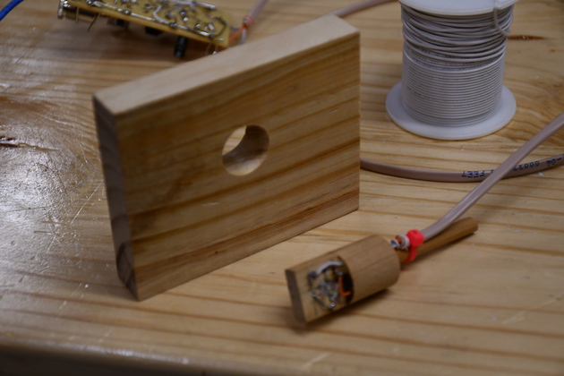
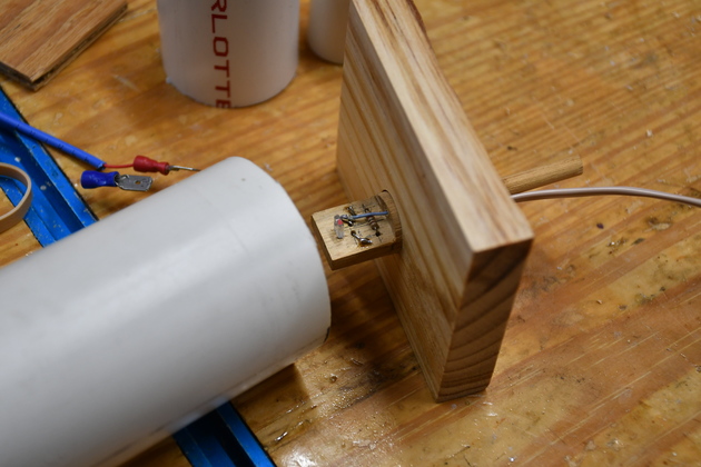
I bored a 3/4" hole in a piece of wood to make sure the sensor would fit and as an end cap for the test tube.
The test cap and sensor.
|
|
Easy does it.
|
|
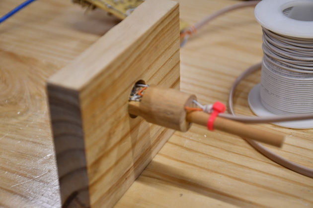
Yes, it does fit.
|
|
The sensor inserted into the test cap.
|
|
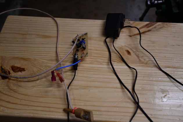
Final sensor attached to the control board and it's switching power supply (a wall wart).
Click to see how the wires feed through the sensor.
Switching power supplies are much more effecient than magnetic power supplies (transformer based).
You can usually tell a switching supply by it's weight and general shape, the magnetic supplies are almost square and switchers are narrower and lighter.
|
|
End cap and sensor about to be placed on the test tube.
|
|
And testing is a success.
BTW, you will note a spool of beige wire on the bench, it is telephone wire (4 cond), I used it to attach the sensor to the controller.
|
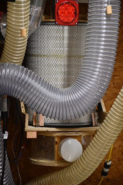
Finished
|
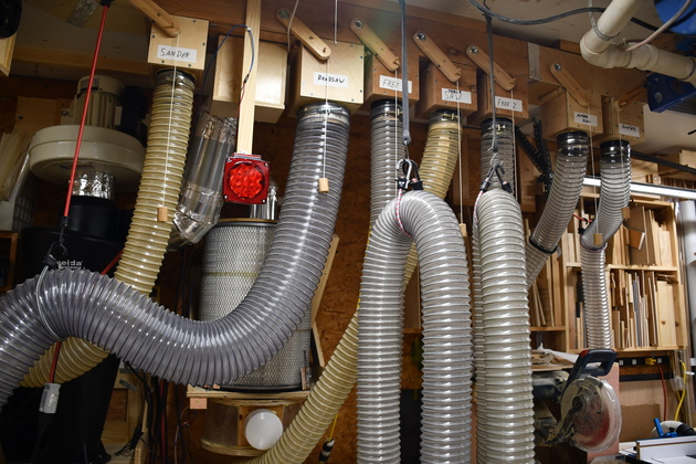
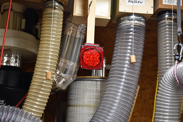
You can see the alert light hanging from the ceiling.
Note the filter behind the alert light and the cyclone to the left.
|
|
Closer look at the alert signal (taillight).
|
|
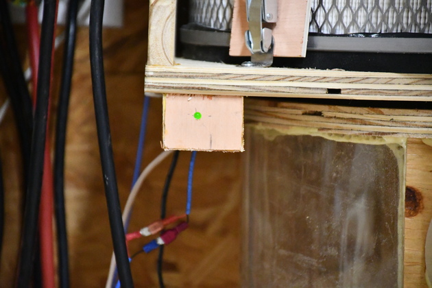
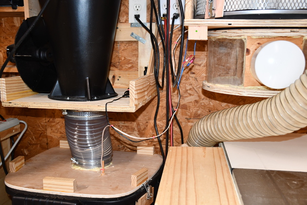
The finished control unit in it's box (little pink box) under the filter shelf.
Notice, I added a green LED to indicate power, its powered from the lights in the room.
All the lights in the shop plug into receptacles in the ceiling, I pulgged an extension into one of these and ran it down to the cyclone shelf where the dust sensor power supply is.
|
|
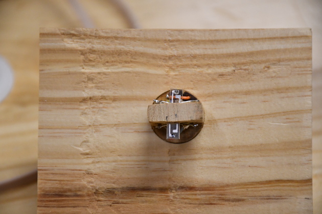
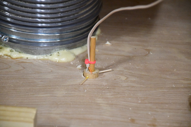
The sensor installed in a 3/4" hole in the top of the dust bin.
It is a snug fit, I can't tell if it leaks any air.
The wooden "spikes" make sure it doesn't get sucked into the bin, the snug fit holds it ok, but I just wanted to make sure.
|
|
Close up of back of sensor, you can see the holes I drilled for the wires to the control board.
|
|
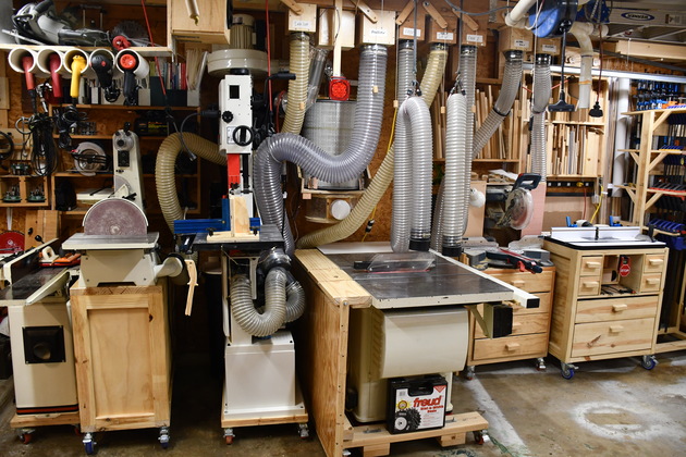
A look at the machine line on the West wall.
Note you can see the alert light.
|
|
Most of the system, you can see the alert light above the filter and the control box below the filter shelf.
|
|
Another look, you can see the control box uner the filter shelf and the sensor in the dust bin top.
|
