| 
| 
| 
|
|
|
|
|
|
When Automating the Dust Collecor system, and because of the DW735 planer's chip exhaust, I realized that I needed a 4" valve that would open under lots of pressure.
Unfortunately, my 4" updraft valves are designed to open/close with the DC off.
There are normally 2 different kinds of dust valves, Knife type, Slider type.
The Knife type has a thin flat piece of metal or plastic which, when closing, slides across the 4" aperture into a pocket on the opposite side.
Since the pocket and side slots cause small vortices (turbulence), there is always a little sawdust accumulated in the slots and pocket.
As the knife slides acros the aperture into the pocket, it tends to pack saw dust into the pocket ultimately preventing the knife from closing all the way, so it must be cleaned frequently.
These are the "cheapie" gates you normally find at most woodworking stores.
The Slider type is a flat piece of metal, plastic, or wood with a round aperture that matches the dust hose interior.
When the slider opens, the aperture moves to align with the hole in the dust nipple, and when it closes the apreture is moved away from the dust path, cutting it off.
There is no pocket to accumulate wood chips.
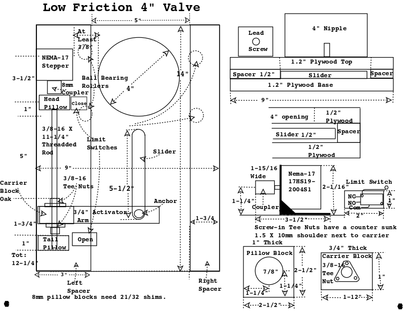
The valve will be made of 1/2" baltic birch, planed, sanded, and painted with polyurethane, so It's very smooth and flat, with a 4" round aperture near one end.
The slider and spacers are made from the same piece of plywood, all plywood is not created equal.
I gently planed all parts of the valve body and the slider was planed one extra time taking off a little less than 1/64" so it would have clearance to move easily.
Since I want this valve to be controlled by an Arduino, actuators are a consideration.
I thought about a servo, the same method as my updraft valves, but it would take a very powerful Servo, then it occurred to me I could use a Lead Screw.
A Lead Screw would need a stepper motor with a T8 (4 start: MA = .78(Torque)) and have a lot more power to open/close the valve.
The problem with this stepper & lead screw actuators is the controller has to be smarter, and drive a lot of current.
Since this valve is about 18' from the DustAuto controller, I'll need a local power supply for the actuator and a driver board adjacent to the valve.
The Ivac electric 4" blast gate is over $100 so I have a fair amount of room in the budget.
I saw Cosmas Bauer on YouTube make a low friction blast gate with ball bearings on each side, interesting idea.
I found a T8 (8mm) Four Start Lead Screw, with two pillow blocks, a coupler, and a pusher nut on Amazon for $12.
I really like the T8 Lead Screw, it should move faster than a threadded rod.
It should take about 18 revs. (3500 steps) to move 5.5" to open or close the valve.
I ordered a 2nd lead screw nut from Amazon.
The actuator bar is about 5.5" with a 1/2" hole drilled 1/2" from the end.
The second Lead Screw Nut will distribute the torque across both nuts, helping prevent the carrier from twisting.
Mechanical Advantage [(πD)/L] of 8mm 4 start = 3.14159 (π).
5-1/2" (travel) / 8mm per rev (.315") = 18 revs. times 200 steps per rev = 3600 pulses.
The NEMA-17 should be able to make 600RPM (10 RPS) which means (2857Hz pulses) or about 1.3 sec to open / close the valve.
18 revs (T8 Lead Screw) at 200 steps/rev = 3600 pulses.
I originally started with a Nema-17 64OzIn but it couldn't quite open the valve under the pressure from the DW-723, so I replaced it with a Nema-17 84 OzIn which works OK.
Nema-17s have 5mm 'D' shafts which the coupler, which came with the lead screw, fits perfectly.
After constructing the valve, connecting it to the DW735, moving the slider while the DW-735 is running requires a 1.5LB pull. This should be well witin the force the NEMA-17 with the T8 Lead Screw can deliver.
Since, at power up, you don't know where a stepper is, I'm using limit switches so the Nano can determine whether the slide is closed or open. The carrier block should always be touching one of the limit switches.
I decided to add the DRV-8825's M0 input to the Nano's digital outputs. I had noticed that all the torque info for this Nema-17 is shown at 1/2 step mode. So by raising or lowering the DRV-8825's M0 input I can switch from full step to half step and see how the slider reacts unnder pressure.
I had to slow down the servo, when opening, to make sure it had enough power. I am thinking of going to a Nema-23 stepper motor which would require a more powerful driver.
|
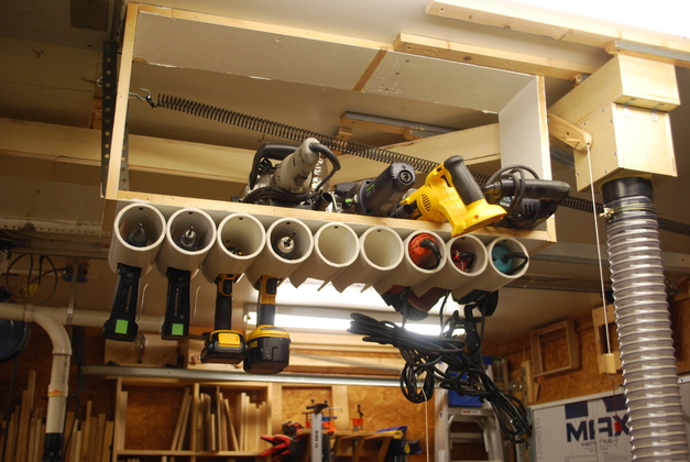
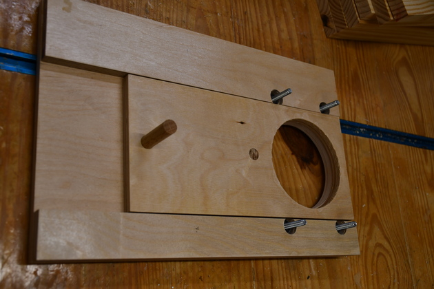
Pic of the small ceiling rack with the DC extension, and it's 4" updraft valve, on the right. This 4" updraft valve will be replaced by the 4" slider valve, note its a tight fit. The valve will need to be at a slight angle to clear the ceiling tool rack, which is OK as long as the 4" holes line up. |
|
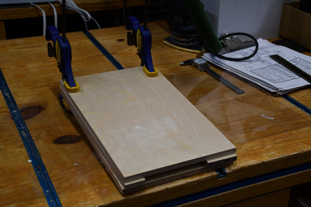
Trial fit before paint. |
|
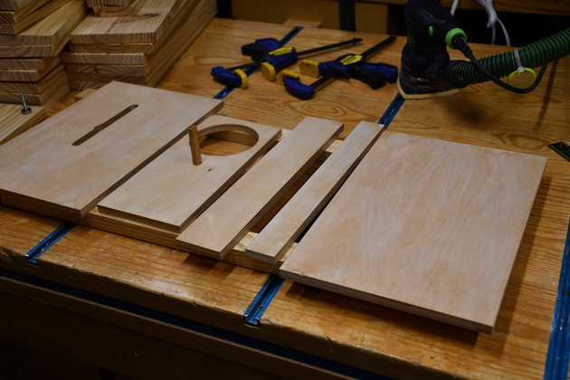
All the valve pieces cut out and planed, ready to paint. |
|
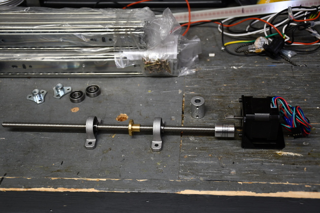
Nema-17 with T8 lead screw, pillow blocks and one follower nut. I subsequently got another follower nut for the final assembly. |
|
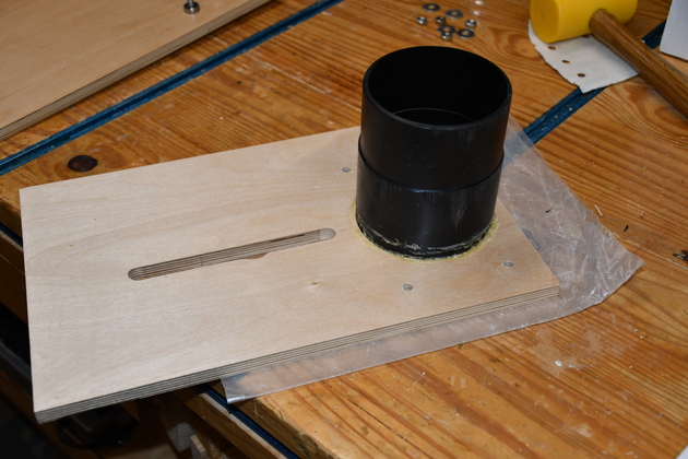
4" dust nipple being glued into valve top. |
|
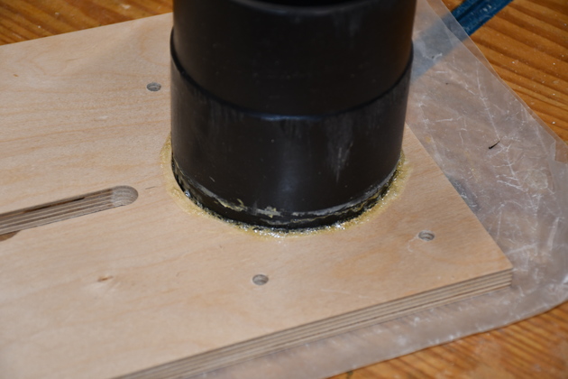
Closer look at glue joint, I use polyurethane glue (like Gorilla Glue), it expandes to fill gaps and makes the 4" nipple joint air tight. Note the glue residue above the joint, I used this particular nipple in an older project. |
|
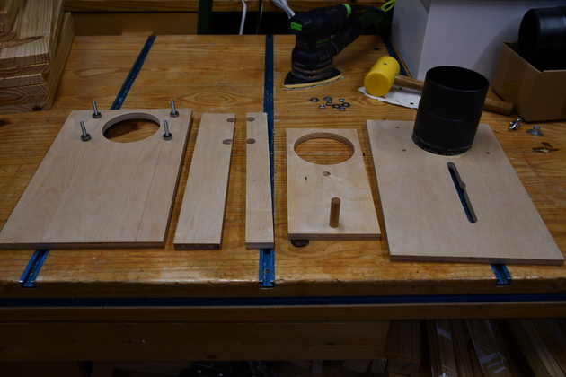
All valve pieces after paint. |
|
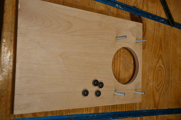
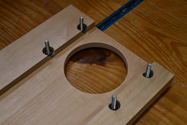
Base with 1/4-20 bolts and bearings. |
|
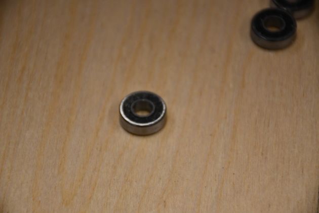
Closer look at ball bearings. They have a 1/4" center hole. |
|
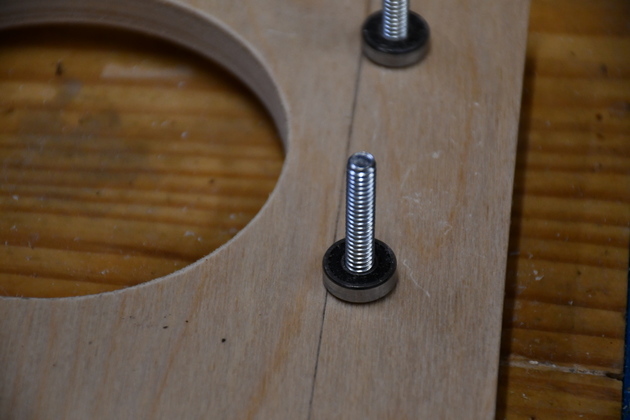
Bearings on the bolts. |
|
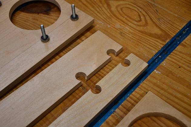
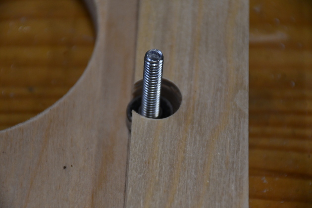
Spacers with bearing clearance holes. |
|
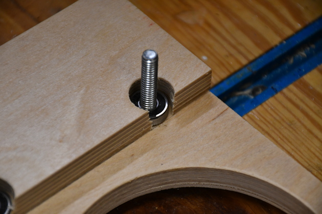
Spacers on base with bearings on the bolts. |
|
Closer look at the bearings on the bolts and how they just protrude into the slider area. |
|
Better pic of bearing protrusion into slider area. |
|
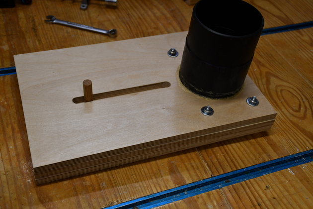
Slider test fit, valve closed. |
|
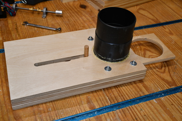
Slider test fit, valve open. |
|
Valve completely assembled, open. |
|
Valve closed. |
|
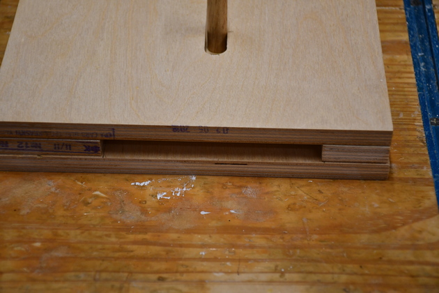
Valve open, note the base / top are a little longer than the slider since I need a little more space to mount lead screw tail pillow etc. |
|
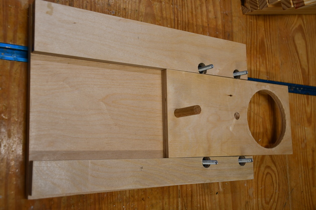
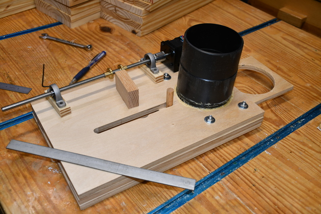
Laying out the Lead Screw, pillow blocks, and carrier block. The most difficult layout/construction item is getting the lead screw exactly parallel with the slot, so the distance between the lead screw and the anchor pin doesn't change as the carrier block and slider move back and forth. Of course you can make the 1/27quot; hole in the actuator arm a 1/2" wide slot, which would allow the anchor pin to move side to side. |
|
I've added the limit switches. This is the way you make a servo from a stepper, although this one only knows open and shut. |
|
The carrier block, drilled, with it's lead screw nuts. |
|
You can see the carrier block has two lead screw nuts, to give it more stability with the offset side load when opening the valve under pressure. |
|
Bottom of carrier block with acutator arm attached. The actuator bar is 3/4" wide flat steel bar 5-1/2" long, the 1/2" hole is drilled 1/2" from the end. I chamfered the 1/2" hole so the bar could easily slip around on the anchorpin. |
|
You can see the actuator arm going from the bottom of the carrier block to the valve anchor pin. The pillow blocks, mounted on standoffs, aligned well. |
|
Better look at the actuator arm as it moves the slider anchor. |
|
With everything mounted. You may notice the "blivet" in the far side of the anchor pin slot, it doesn't cause any problem sincee the actuator bar keeps the anchor pin from straying from the center of the slot. You are looking at the bottom of the valve, it will mount upside down under the plenum. |
|
|
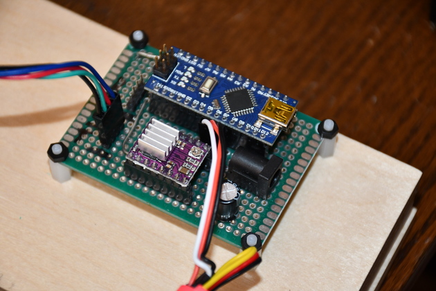
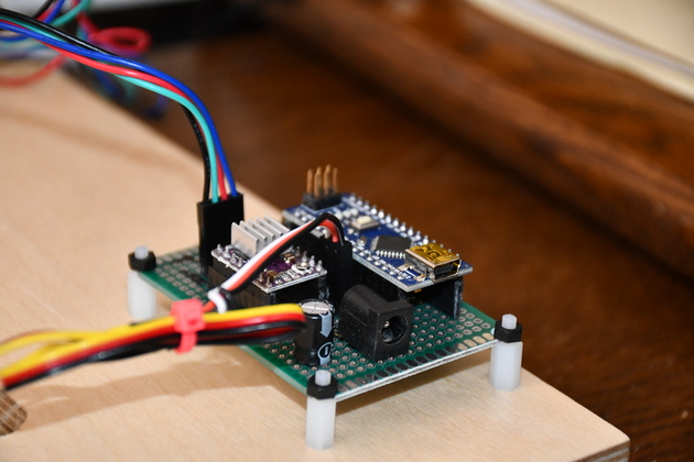
Valve control board mounted. You can see the Nano above and the DRV8825 (purple) below, the 5.1mm receptcal is for 24V valve power. |
|
Close up of control board end, on it's standoffs. |
|
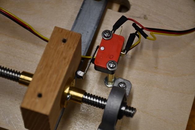
End of valve showing end pillow block, 'Valve Open' limit switch, and control board. |
|
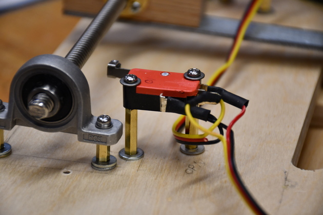
The 'Valve Open' limit switch mounted on it's standoffs. |
|
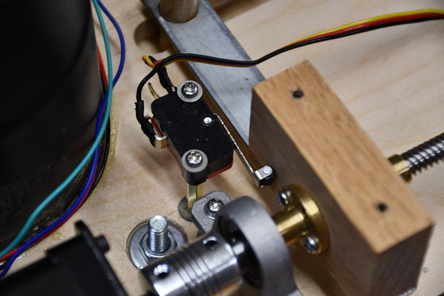
'Valve Closed' limit switch on it's standoffs. |
|
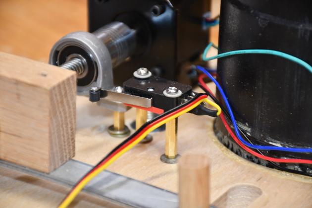
'Valve Closed' limit switch in closed position, with carrier block pushing the switch. Remember, the Nano uses a pullup on this input, the switch is normally closed to ground, so when the switch is pushed the Nano sees a hi. |
|
'Valve Open' limit sitch in depressed position, carrier block pushing it. |
|
|
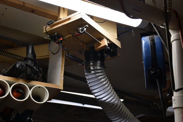
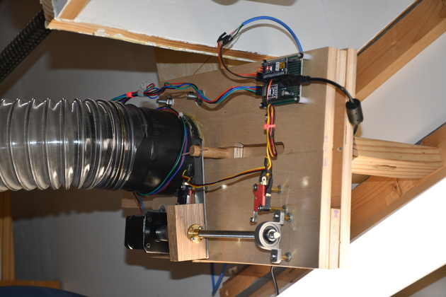
Valve installed on the ceiling plenum near the power hand tool rack. |
|
Closer look at installed valve. You can see the angle, and the 4" holes line up perfectly. |
|
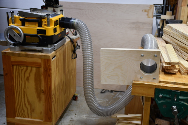
Valve test setup, output of DW-723 connected to valve. Remember, the reason I'm doing this is to have a valve that will open under the pressure created by the DW-723's chip exhaust fan when the planer is turned on. |
|
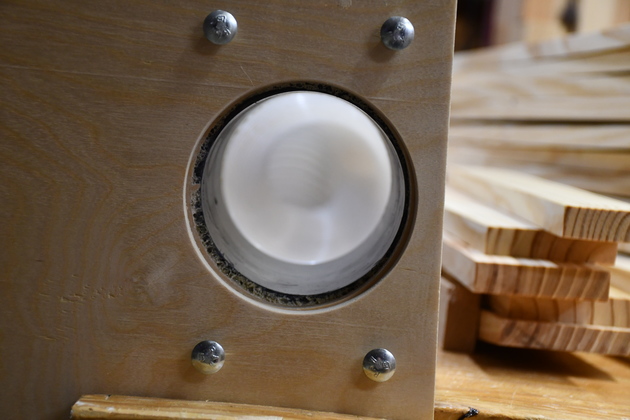
Looking straight through the valve into the 4" dust host from DW-723. Note: I haven't countersunk the heads of the 4 1/4-20 bolts yet, this side (top side) must seal (with a gasket) against the bottom of the plenum. |
|
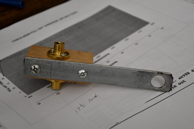
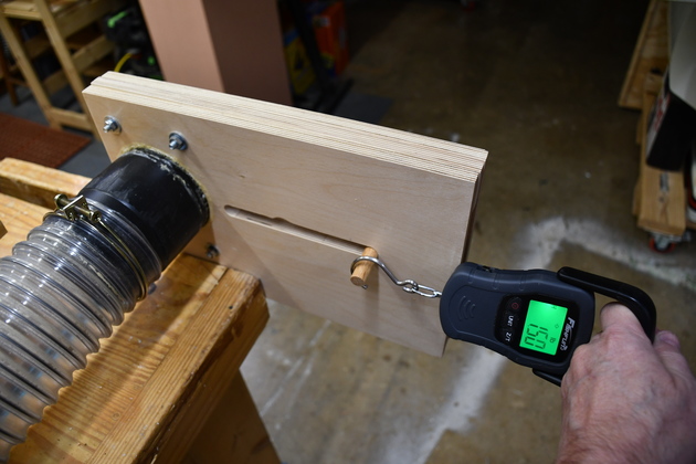
Test force to open valve under pressure.
I started with the valve closed, DW-723 on then pulled the valve open.
Thats the way it will be when you turn the Planer on and let the DustAuto system open the valve and turn the DC on.
|
|
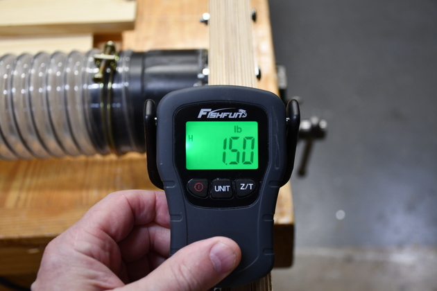
Note 1-1/2# pull while valve is under pressure from Dw-723. I didn't take a pic, but the pull with no air pressure is just few ounces, barely registers on the fish scale. |
|
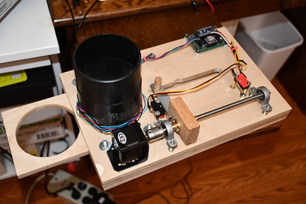
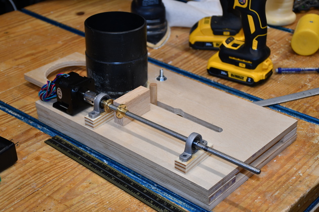
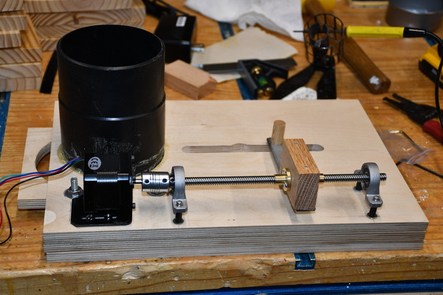
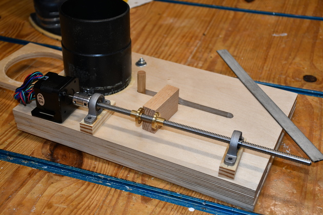
Test fit of stepper, lead screw, pillow blocks (with elevator shims), and carrier block. |
|
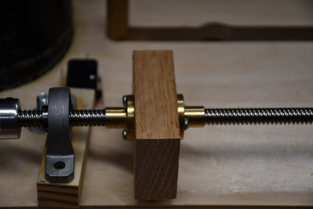
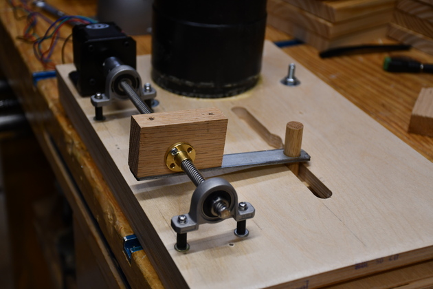
Reverse side pic. Note you can see the two lead screw nuts. The flat bar will be sawed off (5-1/2" long) and hole drilled (1/2" diameter, 1/2" from end of bar) to become the actuator bar. I'll drill a clearance hole in the carrier block for the lead screw and screw holes in the bottom for the actuator bar. The lead screw is obviously longer than needed, so it'll be shortened. |
|
|
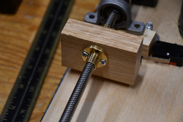
Closer look at the two lead screw nuts attached to the carrier block. |
|
|
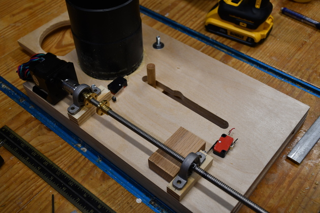
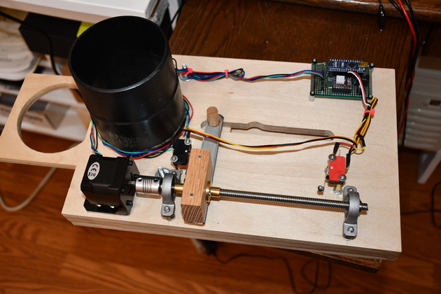
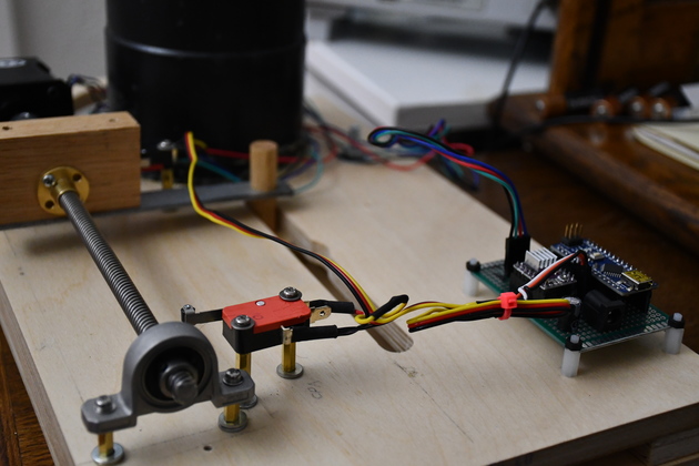
Here is Valve8 assembled, you can see the two limit switchs (red and black devices) attached to the base on standoffs. |
|
|
A closer look at the "Open" limit switch. |

|
|