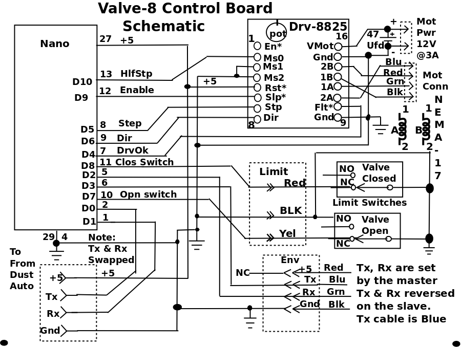
I decided to use another Nano with a DRV-8825 to control the Stepper, so I wouldn't be sending pulses over a 15' wire.
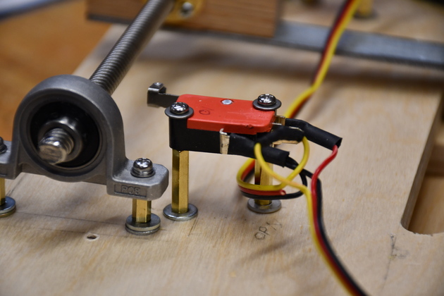
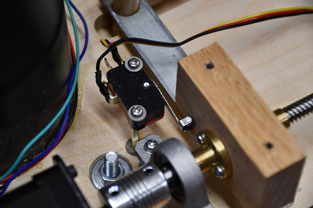
The limit switches will use digital inputs to the Nano, with a pullup.
Limit switch NC (Normally Closed) shorts the input to ground until the carrier block pushes one of the switches (opening it) allowing the input pullup to go hi, so the Nano will see a hi level on the limit switch pin and stop pulsing the motor.
|
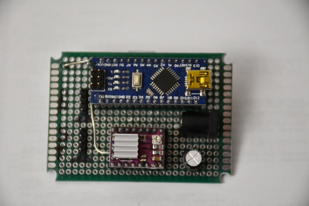
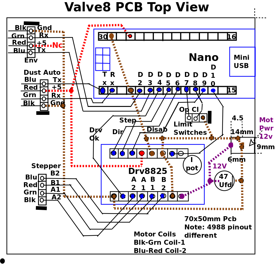
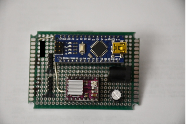
The PC board assembled.
Note the gound loop upper left, for a scope ground.
Most of the gounds are on the bottom side and most of the +5 (Vcc) is on the top.
Note, I drilled out the holes in the corners so I can use larger (wood) screws and standoffs to mount this directly on the valve top.
|
|
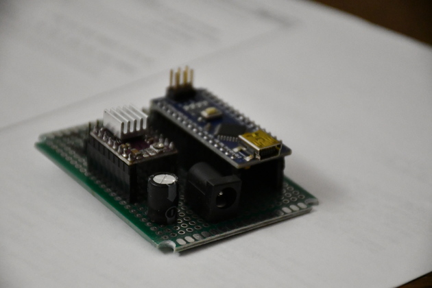
You can see the 12Volt connector near the Nano's USB connector.
|
|
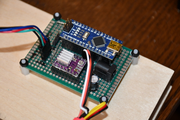
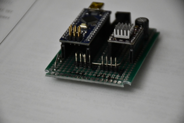
And on the back side, you can see the two 4 pin headers for the link to DustAuto control system (left), and the stepper (right).
You can also see the scope ground on the left.
|
|
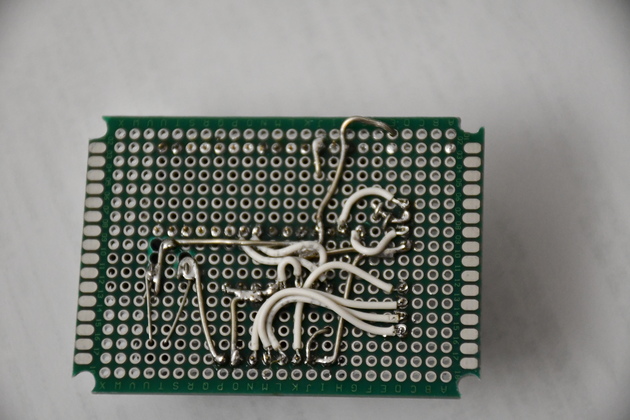
The bottom of the completed PCB.
There are only 9 discrete wires after I laid in the ground and power busses.
|