24C32 Non-Volatile Ram on board DS3231
#include <>
 Things to store in NvRam:
The on-board 24C32 only has 4K bytes of storage.
I'm setting this up to initially use DHCP (Dynamic Host Control Protocol).

	12/24  Hr clock "t/f" 1  byte
	DoDst?: "t/f"         1  byte
	Intensity             1  byte
	Timezone  E,C,M,P     1  byte
  	Dsp Colon "t/f"       1  byte
	Dsp Secs              1  byte
  	use DHCP "t/f"        1  byte
  	IP:                   4  bytes
  	NetMask:              4  bytes
  	GWY:                  4  bytes
  	DNS:                  4  bytes
	WiFi SSID ""          16 bytes
	WiFi PWD ""           16 bytes
  	NTP Server:           16 bytes  // "pool.ntp.org" or local
Breaking Out Pins
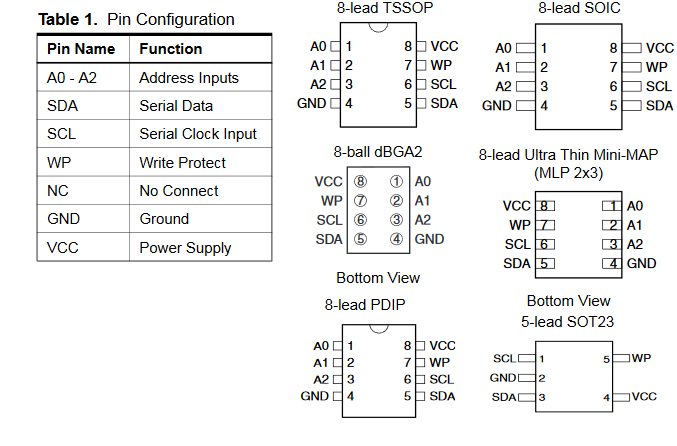
The chip I chose comes in several packages, but because I needed to mount them
on PCBs, I went with the SOIC-8 package, which is a surface-mount variant.
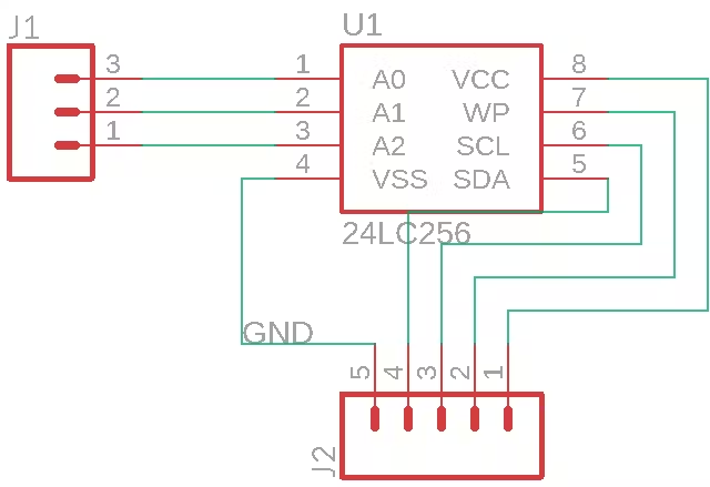
To begin, I added the EEPROM IC part into Eagle, along with a 3-pin header for
the ADDR pins and a 5-pin header for the other pins. Then I simply routed net
segments between the pins to connect them.
Writing New Data
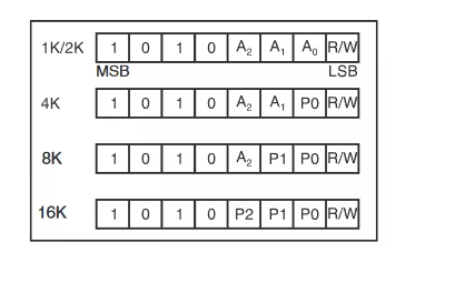
To write data, first ensure the WP (write protect) pin is connected to GND. The
device address is first sent with a value between 0x50 and 0x57. Then an eight
bit must be added on to then end which toggles between reading or writing. To
write, it gets set to 0. To demonstrate, the address byte of the first IC as a
write operation would be 1010000.
Next, an address is specified for the data to be written to, followed by the
byte to be written. Using the Wire library, this looks like:
Wire.beginTransmission( 0x50 );
Wire.write( address );
Wire.write( data );
Wire.endTransmission(); // stop transmitting
Wiring
Connecting the EEPROM chip to an Arduino Uno board was simple. Here is a list of connections:
| |
|
| AT24C02 | | | Uno
|
| GND | | | GND
|
| VCC | | | 5v
|
| SDA | | | SDA
|
| >SCL | | | SCL
| | WP | | | GND (Connect to VCC to disable writing)
|
The address pins are only necessary if more than one EEPROM chips are going to
be used. If that is the case, just increment the three-bit address value for
each new chip. For example, the third IC would have these pins connected:
Reading Data
Reading data from the chip is done in a similar way. First, the target storage
address must be selected. This is done by sending a dummy write command to load
in the target address. Next, one byte is sent containing the device address and
the read/write bit as 1. The EEPROM chip then sends one byte of data in return.
This looks like:
Wire.beginTransmission( 0x50 );
Wire.send( targetAddress );
Wire.endTransmission();
Wire.requestFrom( 0x50, 1 );
If( Wire.available() )
{
byte data = Wire.receive();
}
Wire.endTransmission();
/*F********************************************************************
*
**********************************************************************/
#include <Wire.h>
//************************* DEFINES ************************************
#define ADDR_Ax 0b000 // A2, A1, A0
#define ADDR (0b1010 << 3) + ADDR_Ax
//************************* PROTOTYPES ************************************
void writeI2CByte( byte data_addr, byte data);
byte readI2CByte( byte data_addr );
//************************* VARIABLES ************************************
/*F********************************************************************
*
**********************************************************************/
void
setup()
{
// PUT YOUR SETUP CODE HERE, TO RUN ONCE:
Serial.begin( 9600 );
Wire.begin();
writeI2CByte( 0, 1 );
Serial.println( readI2CByte( 0 ) );
}
/*F********************************************************************
*
**********************************************************************/
void
loop()
{
// PUT YOUR MAIN CODE HERE, TO RUN REPEATEDLY:
}
/*F********************************************************************
*
**********************************************************************/
void
writeI2CByte( byte data_addr, byte data)
{
Wire.beginTransmission( ADDR );
Wire.write( data_addr );
Wire.write( data );
Wire.endTransmission();
}
/*F********************************************************************
*
**********************************************************************/
byte
readI2CByte( byte data_addr )
{
byte data = NULL;
Wire.beginTransmission( ADDR );
Wire.write( data_addr );
Wire.endTransmission();
Wire.requestFrom( ADDR, 1 ); // RETRIEVE 1 RETURNED BYTE
delay( 1 );
if( Wire.available() )
data = Wire.read();
return data;
}