How to Use I2C EEPROM © GPL3+


Expand your board's storage with an I2C-enabled EEPROM chip.
    data collection
Expand your board's storage with an I2C-enabled EEPROM chip.
data collection
| How to Usu I2C EEPROM | What is EEPROM? | Breaking Out Pins | Wiring |
| Writing New Data | Reading Data | Whats Possible | Code |
| Schematics | Comments |
How to Use I2C EEPROM © GPL3+
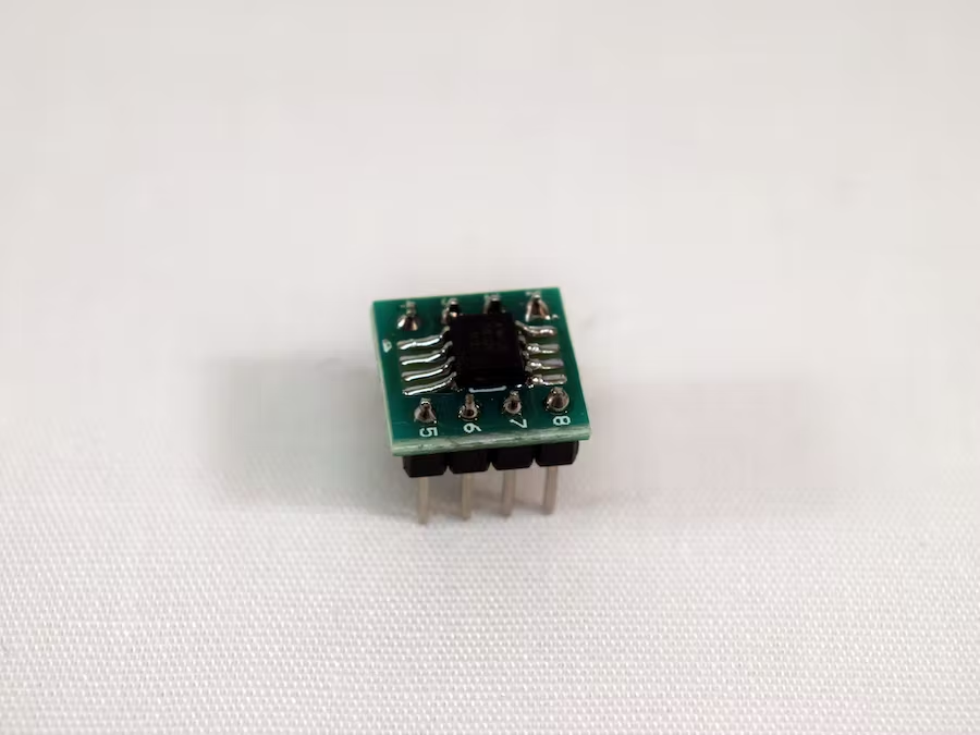
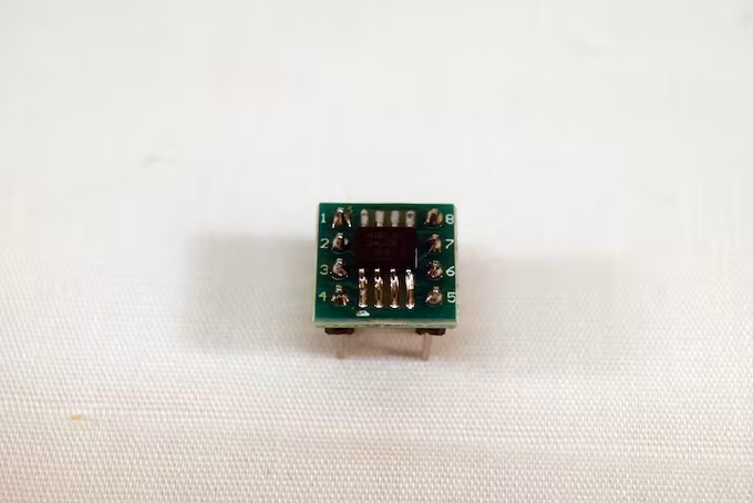
 Next, I laid it all out on a PCB by placing the IC first and then the headers on
either side. I made sure that they were directly lined up, as crossing the paths
adds a lot of unnecessary complexity.
Next, I laid it all out on a PCB by placing the IC first and then the headers on
either side. I made sure that they were directly lined up, as crossing the paths
adds a lot of unnecessary complexity.
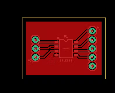 I used Chilipeppr to generate Gcode for my CNC router, which I used to mill the
traces on the board. Then it was simply a matter of soldering everything
together.
I used Chilipeppr to generate Gcode for my CNC router, which I used to mill the
traces on the board. Then it was simply a matter of soldering everything
together.
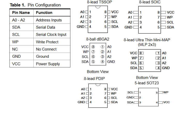
| AT24C02 | | | Uno |
|---|---|---|
| GND | | | GND |
| VCC | | | 5v |
| SDA | | | SDA |
| SCL | | | SCL |
| WP | | | GND (Connect to VCC to disable writing) |
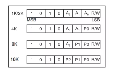 Next, an address is specified for the data to be written to, followed by the
byte to be written. Using the Wire library, this looks like:
Wire.beginTransmission( 0x50 );
Wire.write( address );
Wire.write( data );
Wire.endTransmission(); // STOP TRANSMITTING
Next, an address is specified for the data to be written to, followed by the
byte to be written. Using the Wire library, this looks like:
Wire.beginTransmission( 0x50 );
Wire.write( address );
Wire.write( data );
Wire.endTransmission(); // STOP TRANSMITTING

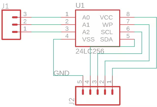
 Uploads/tmp/08ac9522 0ef6 40c9 bd0f bc83986c2805/schematic 6wwtgtkfoi Pins
Uploads/tmp/e169de07 37c2 4224 943b 2be9e806a63b/pinout 2w7mfreext
Uploads/tmp/08ac9522 0ef6 40c9 bd0f bc83986c2805/schematic 6wwtgtkfoi Pins
Uploads/tmp/e169de07 37c2 4224 943b 2be9e806a63b/pinout 2w7mfreext