DRV 8825 Stepper Controller
From: https://lastminuteengineers.com/drv8825-stepper-motor-driver-arduino-tutorial/
Page Origin
Control Stepper Motor with DRV8825 Driver Module & Arduino
 Tutorial For Interfacing DRV8825 Stepper Motor Driver with Arduino
For single-stepper-motor applications, a driver like the L298N is fine, but
if you want to construct your own CNC machine or 3D printer, you’ll need a
dedicated stepper motor driver like the DRV8825.
Due to the simplicity of the step motor control and the variety of stepping
modes provided by the DRV8825 driver, it is an ideal solution for building
applications that require precise and reliable stepper motor control, such as
the movement control of beds, heads, and assemblies in various CNC plotting,
milling, and 3D printer designs.
The fact that it only requires two pins to control the speed and direction of
a bipolar stepper motor like the NEMA 17 is pretty neat, too.
Do you know how stepper motors work?
Stepper motors use a cogged wheel and electromagnets to rotate the wheel one
‘step’ at a time.
Each HIGH pulse sent energizes the coil, attracting the teeth closest to the
cogged wheel and driving the motor one step forward.
Tutorial For Interfacing DRV8825 Stepper Motor Driver with Arduino
For single-stepper-motor applications, a driver like the L298N is fine, but
if you want to construct your own CNC machine or 3D printer, you’ll need a
dedicated stepper motor driver like the DRV8825.
Due to the simplicity of the step motor control and the variety of stepping
modes provided by the DRV8825 driver, it is an ideal solution for building
applications that require precise and reliable stepper motor control, such as
the movement control of beds, heads, and assemblies in various CNC plotting,
milling, and 3D printer designs.
The fact that it only requires two pins to control the speed and direction of
a bipolar stepper motor like the NEMA 17 is pretty neat, too.
Do you know how stepper motors work?
Stepper motors use a cogged wheel and electromagnets to rotate the wheel one
‘step’ at a time.
Each HIGH pulse sent energizes the coil, attracting the teeth closest to the
cogged wheel and driving the motor one step forward.
 stepper motor working animation
The way you pulse these coils greatly affects the behavior of the motor.
stepper motor working animation
The way you pulse these coils greatly affects the behavior of the motor.
- The sequence of pulses determines the spinning direction of the motor.
- The frequency of the pulses determines the speed of the motor.
- The number of pulses determines how far the motor will turn.
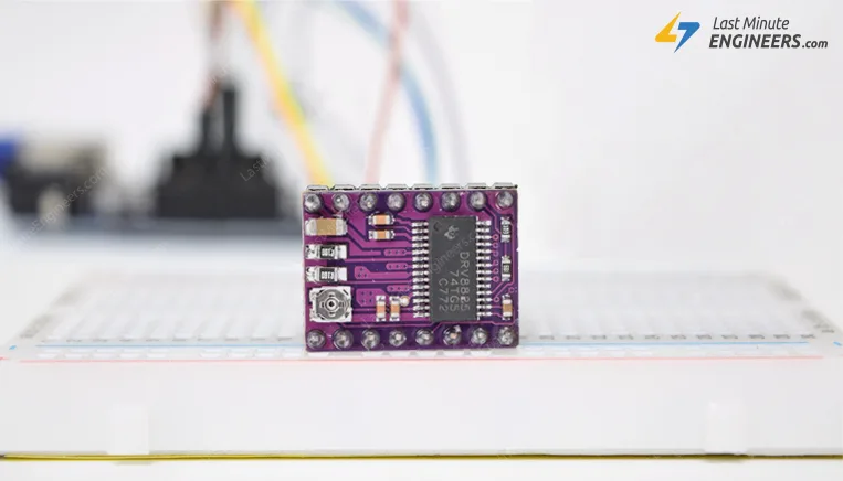
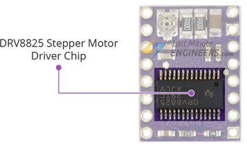
DRV8825 Stepper Motor Driver Chip
At the heart of the module is a microstepping driver from Texas Instruments
– DRV8825. Despite its small stature (0.8″x0.6″), it packs quite a punch.
 DRV8825 Stepper Motor Driver Module
The DRV8825 stepper motor driver has an output drive capacity of up to 45V.
This allows you to control a bipolar stepper motor, such as the NEMA 17, at
up to 2.5A output current per coil.
Furthermore, the output current is regulated, allowing for noiseless operation
of the stepper motor and the elimination of resonance or ringing that is common
in unregulated stepper driver designs.
The driver has a built-in translator for easy operation. This reduces the
number of control pins to just two, one for controlling the steps and the
other for controlling the spinning direction.
The driver offers six different step resolutions: full-step, half-step,
quarter-step, eighth-step, sixteenth-step, and thirty-second-step.
In order to ensure reliable operation, the driver has additional features such
as under-voltage, shoot-through, short circuit, overcurrent, and thermal
protection.
DRV8825 Stepper Motor Driver Module
The DRV8825 stepper motor driver has an output drive capacity of up to 45V.
This allows you to control a bipolar stepper motor, such as the NEMA 17, at
up to 2.5A output current per coil.
Furthermore, the output current is regulated, allowing for noiseless operation
of the stepper motor and the elimination of resonance or ringing that is common
in unregulated stepper driver designs.
The driver has a built-in translator for easy operation. This reduces the
number of control pins to just two, one for controlling the steps and the
other for controlling the spinning direction.
The driver offers six different step resolutions: full-step, half-step,
quarter-step, eighth-step, sixteenth-step, and thirty-second-step.
In order to ensure reliable operation, the driver has additional features such
as under-voltage, shoot-through, short circuit, overcurrent, and thermal
protection.
Technical Specifications
Here are the specifications:
|
|
| Motor output voltage | 8.2V – 45V
|
| Logic voltage | Built-In 3.3V output
|
| Continuous current per phase | 1A
|
| Maximum current per phase | 2.5A
|
| Microstep resolution | full, 1/2, 1/4, 1/8, 1/16, and 1/32
|
DRV8825 Motor Driver Pinout
The DRV8825 driver has a total of 16 pins that connect it to the outside world.
The pinout is as follows:
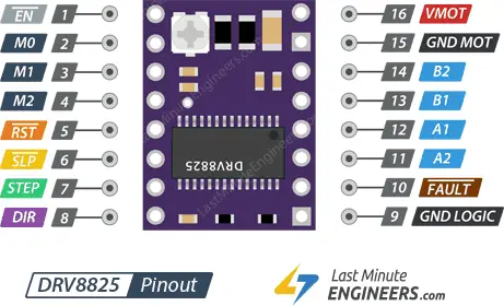 DRV8825 Stepper Motor Driver Pinout
Let’s get to know all the pins one by one.
DRV8825 Stepper Motor Driver Pinout
Let’s get to know all the pins one by one.
Power Pins
Unlike most stepper motor drivers, the DRV8825 has only one power supply connection.
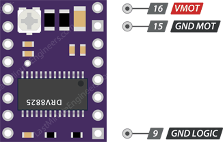 DRV8825 Stepper Motor Driver Motor Power Supply Pins
VMOT and GND MOT supply power to the motor. Any voltage between 8.2V and 45V
can be connected to this pin.
The module doesn’t have a logic supply pin because the DRV8825 draws its power
from the motor power supply using an internal 3V3 voltage regulator. You
should, however, connect your microcontroller’s ground to the GND LOGIC pin.
According to the datasheet, in order to sustain 4A, the motor supply requires
a suitable decoupling capacitor close to the board.
Warning:
Despite the presence of low-ESR ceramic capacitors on board, this driver is
only partially protected against voltage spikes. In some cases, these spikes
can exceed 45V (the maximum voltage rating of the DRV8825), potentially
causing permanent damage to the board and even the motor.
One way to protect the driver from such spikes is to put a large 100μF (or at
least 47μF) electrolytic capacitor across the motor power supply pins.
DRV8825 Stepper Motor Driver Motor Power Supply Pins
VMOT and GND MOT supply power to the motor. Any voltage between 8.2V and 45V
can be connected to this pin.
The module doesn’t have a logic supply pin because the DRV8825 draws its power
from the motor power supply using an internal 3V3 voltage regulator. You
should, however, connect your microcontroller’s ground to the GND LOGIC pin.
According to the datasheet, in order to sustain 4A, the motor supply requires
a suitable decoupling capacitor close to the board.
Warning:
Despite the presence of low-ESR ceramic capacitors on board, this driver is
only partially protected against voltage spikes. In some cases, these spikes
can exceed 45V (the maximum voltage rating of the DRV8825), potentially
causing permanent damage to the board and even the motor.
One way to protect the driver from such spikes is to put a large 100μF (or at
least 47μF) electrolytic capacitor across the motor power supply pins.
Microstep Selection Pins
The DRV8825 driver supports microstepping by dividing a single step into
smaller steps. This is achieved by energizing the coils with intermediate
current levels.
For example, if you choose to drive the NEMA 17 (with 1.8° step angle or 200
steps/revolution) in quarter-step mode, the motor will produce 800 microsteps
per revolution.
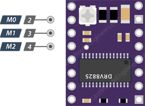 DRV8825 Stepper Motor Driver Microstep Selection Pins
The DRV8825 driver has three step size (resolution) selector inputs: M0, M1
and M2 . By setting the appropriate logic levels for these pins, we can set
the motor to one of six step resolutions.
DRV8825 Stepper Motor Driver Microstep Selection Pins
The DRV8825 driver has three step size (resolution) selector inputs: M0, M1
and M2 . By setting the appropriate logic levels for these pins, we can set
the motor to one of six step resolutions.
| M0 | M1 | M2 | Microstep Resolution
|
| Low | Low | Low | Full step
|
| High | Low | Low | Half step
|
| Low | High | Low | 1/4 step
|
| High | High | Low | 1/8 step
|
| Low | Low | High | 1/16 step
|
| High | Low | High | 1/32 step
|
| Low | High | High | 1/32 step
|
| High | High | High | 1/32 step
|
These three microstep selection pins are pulled LOW by on-board pull-down
resistors, so if you leave them unconnected, the motor will operate in full
step mode.
Control Input Pins
The DRV8825 has two control inputs: STEP and DIR.
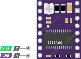 DRV8825 Stepper Motor Driver Motor Control Pins
STEP input controls the microsteps of the motor. Each HIGH pulse sent to this
pin drives the motor according to the number of microsteps determined by the
microstep selection pins. The higher the pulse frequency, the faster the motor
will spin.
DIR input controls the spinning direction of the motor. Pulling it HIGH turns
the motor clockwise, while pulling it LOW turns it counterclockwise.
If you want the motor to only turn in one direction, you can connect the DIR
directly to VCC or GND.
DRV8825 Stepper Motor Driver Motor Control Pins
STEP input controls the microsteps of the motor. Each HIGH pulse sent to this
pin drives the motor according to the number of microsteps determined by the
microstep selection pins. The higher the pulse frequency, the faster the motor
will spin.
DIR input controls the spinning direction of the motor. Pulling it HIGH turns
the motor clockwise, while pulling it LOW turns it counterclockwise.
If you want the motor to only turn in one direction, you can connect the DIR
directly to VCC or GND.
Pins For Controlling Power States
The DRV8825 has three separate inputs for controlling its power states: EN,
RST, and SLP.
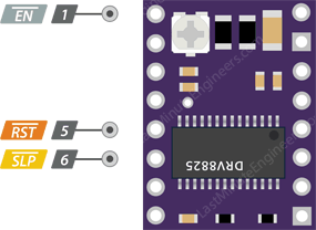 DRV8825 Stepper Motor Driver Power States Control Pins
EN is an active low input pin. When this pin is pulled LOW, the DRV8825 driver
is enabled. By default, this pin is pulled low, so unless you pull it high,
the driver is always enabled. This pin is particularly useful when implementing
an emergency stop or shutdown system.
SLP is an active low input pin. Pulling this pin LOW puts the driver into sleep
mode, reducing power consumption to a minimum. You can use this to save power,
especially when the motor is not in use.
RST is an active low input as well. When this pin is pulled LOW, all STEP
inputs are ignored. It also resets the driver by setting the internal
translator to a predefined “home” state. Home state is basically the initial
position from which the motor starts, and it varies based on microstep
resolution.
Note
that you must provide a 1 ms delay after the wake-up event (logic HIGH on the
SLEEP pin) before issuing a Step command to allow the charge pump to stabilize.
DRV8825 Stepper Motor Driver Power States Control Pins
EN is an active low input pin. When this pin is pulled LOW, the DRV8825 driver
is enabled. By default, this pin is pulled low, so unless you pull it high,
the driver is always enabled. This pin is particularly useful when implementing
an emergency stop or shutdown system.
SLP is an active low input pin. Pulling this pin LOW puts the driver into sleep
mode, reducing power consumption to a minimum. You can use this to save power,
especially when the motor is not in use.
RST is an active low input as well. When this pin is pulled LOW, all STEP
inputs are ignored. It also resets the driver by setting the internal
translator to a predefined “home” state. Home state is basically the initial
position from which the motor starts, and it varies based on microstep
resolution.
Note
that you must provide a 1 ms delay after the wake-up event (logic HIGH on the
SLEEP pin) before issuing a Step command to allow the charge pump to stabilize.
Fault Detection Pin
The DRV8825 has a FAULT output that drives LOW whenever the H-bridge FETs are
disabled as the result of over-current protection or thermal shutdown.
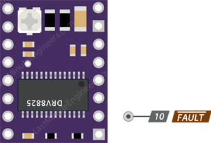 DRV8825 Stepper Motor Driver Fault Detection Pins
The Fault pin is typically shorted to the SLEEP pin; therefore, whenever the
Fault pin is driven LOW, the entire chip is disabled. And it will remain
disabled until it is either RESET or Motor Voltage VMOT is removed and
reapplied.
DRV8825 Stepper Motor Driver Fault Detection Pins
The Fault pin is typically shorted to the SLEEP pin; therefore, whenever the
Fault pin is driven LOW, the entire chip is disabled. And it will remain
disabled until it is either RESET or Motor Voltage VMOT is removed and
reapplied.
Output Pins
The output channels of the DRV8825 motor driver are broken out to the side of
the module with pins B2, B1, A1 and A2 pins.
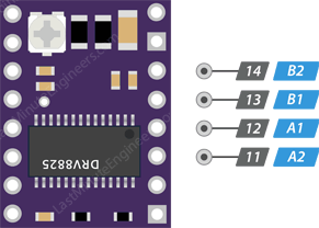 DRV8825 Stepper Motor Driver Motor Connections
You can connect any small to medium-sized bipolar stepper motor, such as NEMA
17, to these pins.
Each output pin can supply up to 2.5A to the motor. The amount of current
supplied to the motor, however, depends on the power supply, cooling system,
and current limiting setting of the system.
DRV8825 Stepper Motor Driver Motor Connections
You can connect any small to medium-sized bipolar stepper motor, such as NEMA
17, to these pins.
Each output pin can supply up to 2.5A to the motor. The amount of current
supplied to the motor, however, depends on the power supply, cooling system,
and current limiting setting of the system.
Cooling System – Heatsink
Excessive power dissipation of the DRV8825 driver IC causes a temperature rise,
which could potentially damage the IC if it exceeds its capacity.
Despite having a maximum current rating of 2.5A per coil, the DRV8825 driver
IC can only supply about 1.5A per coil without overheating. To achieve more
than 1.5A per coil, a heat sink or other cooling method is required.
 DRV8825 Stepper Motor Driver Heatsink
The DRV8825 driver usually comes with the heatsink. It is recommended that you
install the heatsink before using the driver.
DRV8825 Stepper Motor Driver Heatsink
The DRV8825 driver usually comes with the heatsink. It is recommended that you
install the heatsink before using the driver.
Current limiting
Before running the motor, you must limit the maximum current flowing through
the stepper coils so that it does not exceed the motor’s rated current.
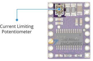 DRV8825 Stepper Motor Driver Current Limiting Potentiometer
The DRV8825 driver includes a small trimmer potentiometer for setting the
current limit.
There are two methods for making this adjustment:
DRV8825 Stepper Motor Driver Current Limiting Potentiometer
The DRV8825 driver includes a small trimmer potentiometer for setting the
current limit.
There are two methods for making this adjustment:
Method 1:
In this method, the current limit is determined by measuring the voltage (Vref)
at the “ref” pin.
- Take a look at the datasheet for your stepper motor. Make a note of the
rated current. In our case, NEMA 17 200steps/rev, 12V 350mA is used.
- Disconnect the three microstep selection pins to put the driver in full-step mode.
- Hold the motor in a fixed position without clocking the STEP input.
- Measure the voltage (Vref) on the metal trimmer pot as you adjust it.
- Adjust the Vref voltage by using the formula
Vref = Current Limit / 2
For example, if your motor is rated at 350mA, you would set the reference
voltage to 0.175V.
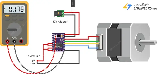 measuring vref voltage setting current limit for drv8825 with multimeter
You can make this adjustment quickly and easily by connecting one end of the
alligator clip test lead to the shank of a metal screwdriver and the other end
to your multimeter. This allows you to measure the voltage while making the
adjustment.
measuring vref voltage setting current limit for drv8825 with multimeter
You can make this adjustment quickly and easily by connecting one end of the
alligator clip test lead to the shank of a metal screwdriver and the other end
to your multimeter. This allows you to measure the voltage while making the
adjustment.
Method 2:
In this method, the current limit is determined by measuring the current flowing through the coil.
- Take a look at the datasheet for your stepper motor. Make a note of the
rated current. In our case, NEMA 17 200steps/rev, 12V 350mA is used.
- Disconnect the three microstep selection pins to put the driver in full-step mode.
- Hold the motor in a fixed position without clocking the STEP input.
- Put the ammeter in series with one of the coils on your stepper motor and
measure the actual current flowing.
- Take a small screwdriver and adjust the current limit potentiometer until
you reach the rated current.
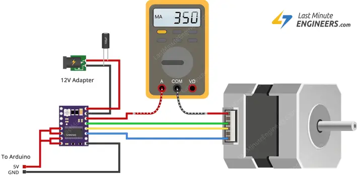 measuring coil current setting current limit for drv8825 with multimeter
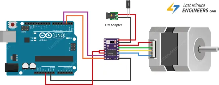
Wiring a DRV8825 Stepper Motor Driver to an Arduino
Now that we know everything about the driver, let’s hook it up to our Arduino.
The connections are straightforward. Start by connecting the RST pin to the
adjacent SLP/SLEEP pin and 5V on the Arduino to keep the driver enabled.
Connect the GND LOGIC pin to the Arduino’s ground pin. Connect the DIR and
STEP input pins to the Arduino’s digital output pins #2 and #3.
Connect the stepper motor to the B2, B1, A1, and A2 pins. Actually, the
DRV8825 module is conveniently laid out to match the 4-pin connector on
bipolar stepper motors, so that shouldn’t be a problem.
Warning:
Do not attempt to connect or disconnect the stepper motor while the driver
is in operation; doing so could damage the driver.
Keep the microstep selection pins disconnected if you want to run the motor in
full step mode.
Finally, connect the motor power supply to the VMOT and GND MOT pins. Remember
to put a large 100μF decoupling electrolytic capacitor across the motor power
supply pins to avoid large voltage spikes.
Wiring Nema 17 Stepper Motor to DRV8825 driver & Arduino
Arduino Code – Without a Library
The sketch below will show you how to control the speed and spinning direction
of a bipolar stepper motor using the DRV8825 stepper motor driver and can
serve as the basis for more practical experiments and projects.
/*H*****************************************************
* Define pin connections & motor's steps per revolution
*******************************************************/
// **************** DEFINES ****************************
// **************** PROTOTYPES *************************
// **************** VARIABLES **************************
const int dirPin = 2;
const int stepPin = 3;
const int stepsPerRevolution = 200;
/*F*****************************************************
*
*******************************************************/
void
setup()
{ // DECLARE PINS AS OUTPUTS
pinMode( stepPin, OUTPUT);
pinMode( dirPin, OUTPUT);
}
/*F*****************************************************
*
*******************************************************/
void
loop()
{ // SET MOTOR DIRECTION CLOCKWISE
digitalWrite( dirPin, HIGH);
// Spin motor slowly
for( int x = 0; x < stepsPerRevolution; x++)
{
digitalWrite( stepPin, HIGH );
delayMicroseconds( 2000 );
digitalWrite( stepPin, LOW );
delayMicroseconds( 2000 );
}
delay( 1000 ); // WAIT A SECOND
digitalWrite( dirPin, LOW ); // SET MOTOR DIRECTION COUNTERCLOCKWISE
for( int x = 0; x < stepsPerRevolution; x++) // SPIN MOTOR QUICKLY
{
digitalWrite( stepPin, HIGH );
delayMicroseconds( 1000 );
digitalWrite( stepPin, LOW );
delayMicroseconds( 1000 );
}
delay( 1000 ); // WAIT A SECOND
}
Code Explanation:
The sketch begins by defining the Arduino pins to which the DRV8825’s STEP and
DIR pins are connected. A variable called stepsPerRevolution is also defined.
You can set it to match the specs of your stepper motor.
const int dirPin = 2;
const int stepPin = 3;
const int stepsPerRevolution = 200;
In the setup section, all motor control pins are configured as digital OUTPUT.
pinMode( stepPin, OUTPUT);
pinMode( dirPin, OUTPUT);
In the loop section, the motor is rotated slowly clockwise and then rapidly
counterclockwise with one second intervals.
Controlling the Spinning Direction: To control the spinning direction of the
motor, the DIR pin is set HIGH or LOW. A HIGH input turns the motor clockwise,
while a LOW input turns it counterclockwise.
digitalWrite( dirPin, HIGH );
Controlling Speed: The frequency of pulses sent to the STEP pin determines the
speed of the motor. The higher the pulse frequency, the faster the motor runs.
A pulse is nothing but pulling the output HIGH, waiting a bit, then pulling it
LOW and waiting again. By adjusting the delay between two pulses, you can alter
the frequency of the pulses and thus the speed of the motor.
for( int x = 0; x < stepsPerRevolution; x++)
{
digitalWrite( stepPin, HIGH );
delayMicroseconds( 1000 );
digitalWrite( stepPin, LOW );
delayMicroseconds( 1000 );
}
Arduino Code – Using AccelStepper library
Controlling a stepper without a library is perfectly fine for simple, single
motor applications. However, if you want to control multiple steppers, you’ll
need to use a library.
So, for our next experiment, we will use an advanced stepper motor library
called AccelStepper library. It supports:
- Acceleration and deceleration.
- Multiple simultaneous steppers, with independent concurrent stepping on
each stepper.
This library is not included in the Arduino IDE, so you must first install it.
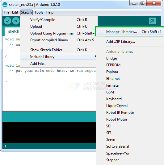
Library Installation
To install the library navigate to Sketch > Include Libraries > Manage Libraries…
Wait for Library Manager to download the library index and update the list of
installed libraries.
manage libraries
Filter your search by typing ‘accelstepper’. Click on the first entry and then
select Install.
 installing accelstepper library
Arduino Code
Here is a simple sketch that accelerates the stepper motor in one direction and
then decelerates to come to rest. After one revolution, the motor reverses its
spinning direction and repeats the process.
/*H*******************************************************
*
*********************************************************/
#include // INCLUDE THE AccelStepper lIBRARY
// **************** DEFINES ****************************
#define motorInterfaceType 1 // DEFINE MOTOR INTERFACE TYPE
// **************** PROTOTYPES *************************
// **************** VARIABLES **************************
const int dirPin = 2; // DEFINE PIN CONNECTIONS
const int stepPin = 3;
AccelStepper myStepper( motorInterfaceType, stepPin, dirPin );
/*F*****************************************************
*
*******************************************************/
void
setup()
{ // SET MAXIMUM SPEED, ACCELERATION FACTOR, INITIAL SPEED AND TARGET POSITION
myStepper.setMaxSpeed( 1000 );
myStepper.setAcceleration( 50 );
myStepper.setSpeed( 200 );
myStepper.moveTo( 200 );
}
/*F*****************************************************
*
*******************************************************/
void
loop()
{ // CHANGE DIRECTION ONCE MOTOR REACHES TARGET POSITION
if( myStepper.distanceToGo() == 0)
myStepper.moveTo( -myStepper.currentPosition() );
myStepper.run(); // MOVE MOTOR ONE STEP
}
Code Explanation:
The sketch begins by including the newly installed AccelStepper library.
#include
First, the Arduino pins are defined, to which the DRV8825’s STEP and DIR pins
are connected. The motorInterfaceType is also set to 1. (1 means an external
stepper driver with step and direction pins).
const int dirPin = 2; // DEFINE PIN CONNECTIONS
const int stepPin = 3;
#define motorInterfaceType 1 // DEFINE MOTOR INTERFACE TYPE
Following that, an instance of the stepper library named myStepper is created.
AccelStepper myStepper( motorInterfaceType, stepPin, dirPin);
In the setup function, the maximum permitted speed of the motor is set to 1000
(the motor will accelerate up to this speed when we run it). The
acceleration/deceleration rate is then set to add acceleration and deceleration
to the stepper motor’s movements.
The desired constant speed is set to 200. And, because the NEMA 17 takes 200
steps per turn, the target position is also set to 200.
void setup()
{
myStepper.setMaxSpeed( 1000 );
myStepper.setAcceleration( 50 );
myStepper.setSpeed( 200 );
myStepper.moveTo( 200 );
}
In the loop function, an if statement is used to determine how far the motor
needs to travel (by reading the distanceToGo property) before reaching the
target position (set by moveTo). When the distanceToGo reaches zero, the motor
is rotated in the opposite direction by setting the moveTo position to negative
of its current position.
At the bottom of the loop, you’ll notice that the run() function is called.
This is the most critical function because the stepper will not move unless
this function is executed.
/*F*****************************************************
*
*******************************************************/
void
loop()
{
if( myStepper.distanceToGo() == 0)
myStepper.moveTo( -myStepper.currentPosition());
myStepper.run();
}

Click For Larger Pic
