As I was designing the large DC automation system, I knew I would need manual input to open either of the two FREE valves and, possibly, the planer valve.
Next I thought about opening two valves at the same time for the lathe.
I first thought of buttons, thats 4, but then I realized it might be really handy to have extra inputs such as cycle all valves without starting the DC (to clean out large splinters),
So I considered a small data terminal as the input device for the DC Automation system.
Back in the "olden days", when I worked at TI, I built a small data terminal that we used to control our test systems.
The TI data terminal had a 16 key keypad, and an 8 alphanumeric character LED display.
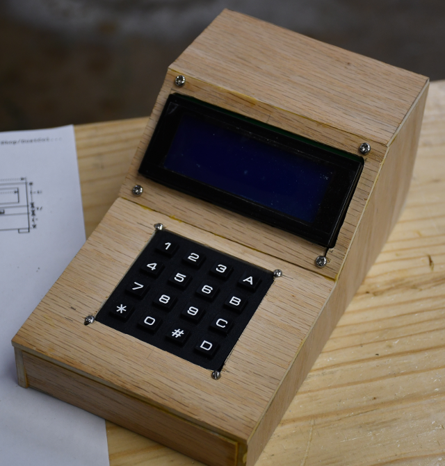
Recently, it occurred to me that the 20x4 LCD display and a 16 key keypad are very cheap and would make a very keen data terminal, and suitable to operate the auotmated DC system.
This data terminal would also make it nice, to display results, when I need to take a project into the shop to gather data.
A nano would be ideal to operate this data terminal, a 16 key keypad, and a PCF8574 I/O Extender.
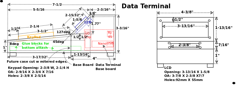
The cabinet is made from a piece of 3/16 plywood about 20" x 7-1/2".
I'll miter the edges of all but the bottom which will fit inside the sides, front, and back, screwed to glue blocks.
I'm also going to move the Computer PCB to the cabinet's base instead of the side.
That will make access a lot easier.
|
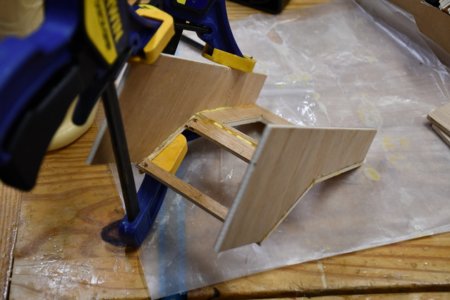
Gluing box parts together.
If I make another I'll make a wooden form to assemble the box on, I'll also miter the plywood corners so you can't see plywood edges.
Sorry I didn't get any pics when sawing out the box's pieces.
|
|
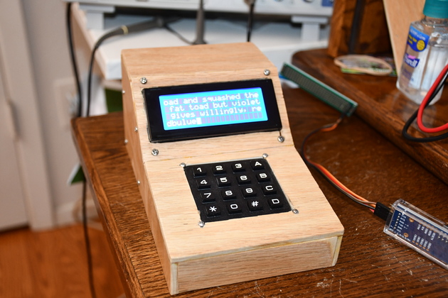
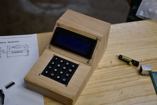
Makes a decent little terminal.
I still have to sand some corners & edges.
|
|
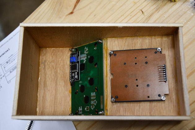
A little closer look at the inside.
|
|
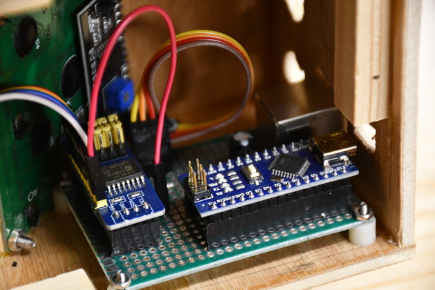
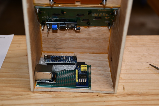
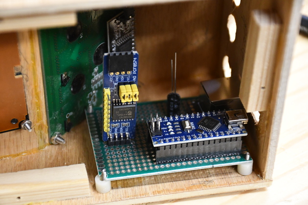
The computer (Nano) I/O expander, RJ-45 connector all on a small Arduino breakout.
Here I'm checking for size and location.
I'll mount the board on standoffs to the inside of the box, with holes for the Nano's USB and the Rj-45 to be accessed from outside.
Also I straightened the 4 LCD's PCF8574 (backpack) pins, again to make it easier to plug when mounted.
I'll drill a few holes at the top back and under the front for ventillation.
|
|
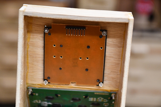
Note the pins on the keypad, I mounted them pointing toward the top of the keypad to make it easier to install in this box.
|
|
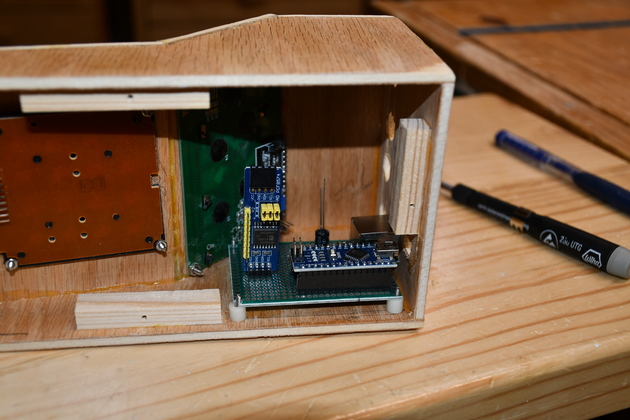
Component fit, the circuit board will be attached to the left side of the cabinet.
Also, I've added the glue blocks to support the cabinet bottom.
I will be moving the DT circuit board to the base instead of the side of the cabinet.
|
|
Closer look, all the components except cables.
I still don't like the I/O Expander standing vertically, it doesn't look or feel stable.
|
|
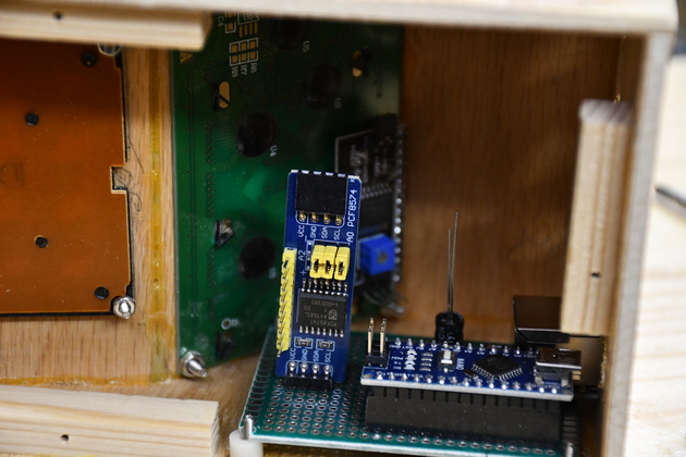
Different angle, a little better detail.
Note how neat the Nano snuggles in with it's USB nearly against the back.
The I/O Expander will actually be plugged into a 4-pin header in the same location.
You can also see the RJ-45's housing beyond the Nano.
In the future I won't use a header for the RJ-45 conn, it'll have a 4pin flat connector, probably a JST connector.
I'll also mount the main PCB on the base instead of the side, as shown here.
|
|
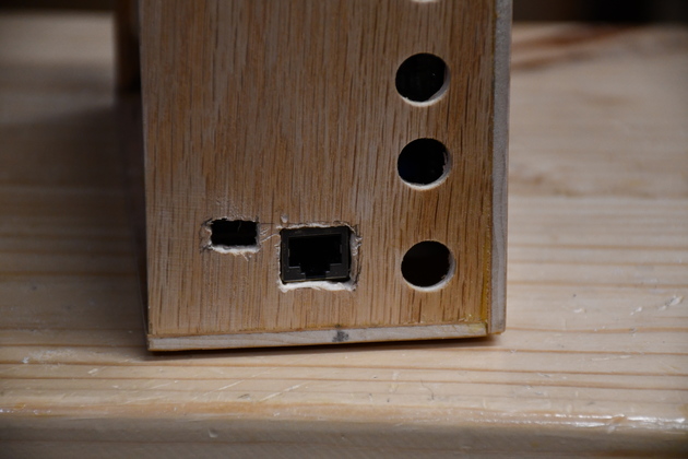
I gnawed out the holes for the RJ-45 and USB conns.
Also, note the air vent holes.
In the future I'm going to use a 4 pin flat connector, it will greatly reduce the cost and simplify the construction.
|
|
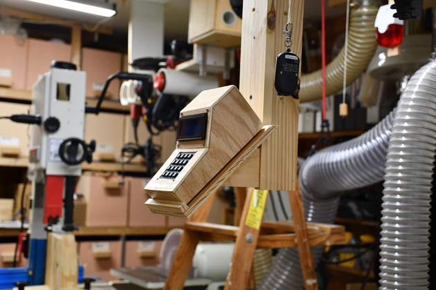
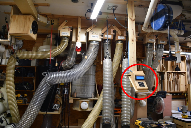
The
data terminal (Red Circle), (mounted on it's celing support, in front of most of the 6" Dust Collection System.
|
|
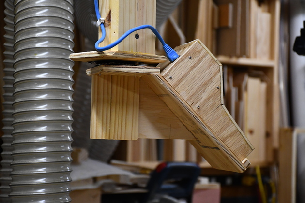
The data terminal on it's ceiling support rotated right on its lazy susan.
|