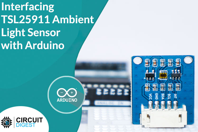
 Interfacing TSL25911 Sensor with Arduino
Detecting the amount of light in the ambiance is necessary for many areas of our
everyday life, and the sensors which can do this are called light sensors, the
most primitive light sensor is a humble LDR. But you can find much more advanced
types of light sensors being used in automatic lighting systems for smartphones
and other smart devices. The perfect example of such a scenario is the
auto-brightness control of our smartphones or laptops. The amount of light is
measured by such devices and the screen brightness is adjusted proportionally to
the ambient light. This avoids having the screen be too bright when the user's
pupils are adapted for vision in a dark room, or too dim when the device is used
outdoors in the daytime. Dimming the screen on a mobile device also prolongs the
lifetime of the battery. So, in this Arduino interfacing tutorial series let’s
look at such a sensor module built around the TSL25911 light sensor.
Interfacing TSL25911 Sensor with Arduino
Detecting the amount of light in the ambiance is necessary for many areas of our
everyday life, and the sensors which can do this are called light sensors, the
most primitive light sensor is a humble LDR. But you can find much more advanced
types of light sensors being used in automatic lighting systems for smartphones
and other smart devices. The perfect example of such a scenario is the
auto-brightness control of our smartphones or laptops. The amount of light is
measured by such devices and the screen brightness is adjusted proportionally to
the ambient light. This avoids having the screen be too bright when the user's
pupils are adapted for vision in a dark room, or too dim when the device is used
outdoors in the daytime. Dimming the screen on a mobile device also prolongs the
lifetime of the battery. So, in this Arduino interfacing tutorial series let’s
look at such a sensor module built around the TSL25911 light sensor.
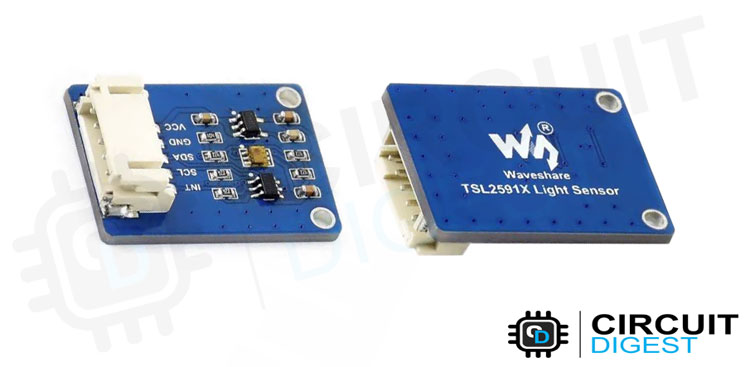
TSL25911 Ambient Light Sensor Module
 TSL25911 Ambient Light Sensor Module
This is a high-sensitivity digital ambient light sensor module based on the
TSL25911fn chip from ams. It can sense the ambient light intensity around and
output it through the I2C interface. The output data uses a formula to derive
the illuminance in lux (ambient light intensity) to approximate the human eye
response. We have previously used the BH1750 with Arduino which can also measure
light intensity in LUX, you can check it out if you are interested.
TSL25911 Ambient Light Sensor Module
This is a high-sensitivity digital ambient light sensor module based on the
TSL25911fn chip from ams. It can sense the ambient light intensity around and
output it through the I2C interface. The output data uses a formula to derive
the illuminance in lux (ambient light intensity) to approximate the human eye
response. We have previously used the BH1750 with Arduino which can also measure
light intensity in LUX, you can check it out if you are interested.
Features:
| Adopts TSL25911FN, measures infrared plus visible light. |
| Embedded ADC, direct light intensity signal output to I2C interface, less |
| noise jamming. High sensitivity up to 188uLux, wide dynamic range up to 600M:1. |
| Embedded infrared-responding photodiode allows precise measuring even in a |
| strong infrared noise environment. |
| Provides interrupt output with programmable upper and lower thresholds. |
| Onboard voltage translator, compatible with 3.3V/5V operating voltage. |
TSL25911 Sensor Module Pinout
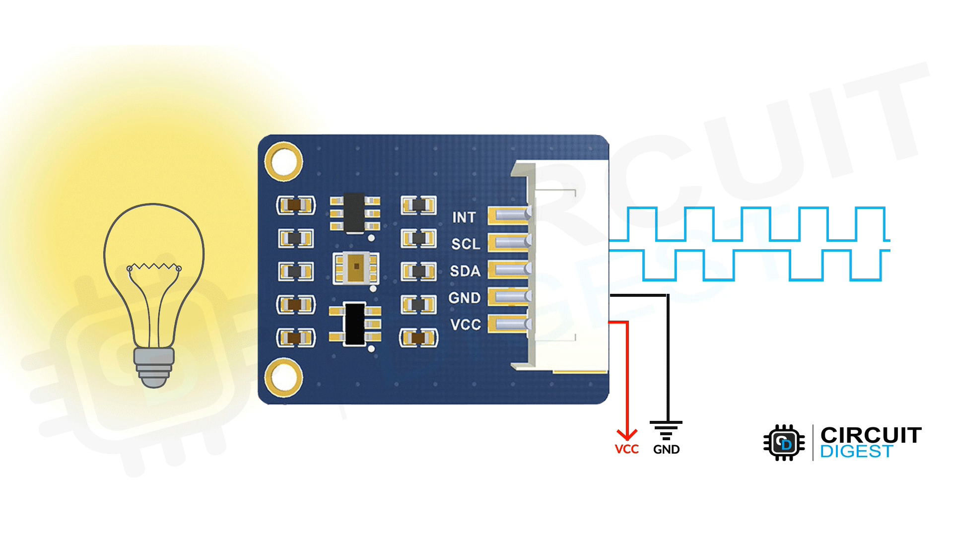
 The TSL25911 sensor module has a total of 5 pins. Two power pins, one interrupt
pin, and two I2C pins. The pinout of the module is as follows:
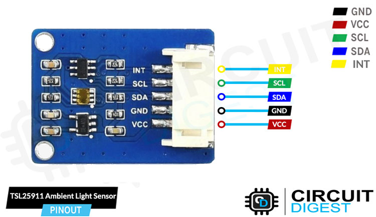
TSL25911 Ambient Light Sensor Module Pinout
VCC - Provides power for the module, Connect to the 5V pin of the Arduino.
GND - Ground Connected to Ground pin of the Arduino.
SCL -Serial Clock Used for providing clock pulse for I2C Communication.
SDA - Serial Data Used for transferring Data through I2C communication.
INT – Interrupt Pin.
The TSL25911 sensor module has a total of 5 pins. Two power pins, one interrupt
pin, and two I2C pins. The pinout of the module is as follows:
TSL25911 Ambient Light Sensor Module Pinout
VCC - Provides power for the module, Connect to the 5V pin of the Arduino.
GND - Ground Connected to Ground pin of the Arduino.
SCL -Serial Clock Used for providing clock pulse for I2C Communication.
SDA - Serial Data Used for transferring Data through I2C communication.
INT – Interrupt Pin.
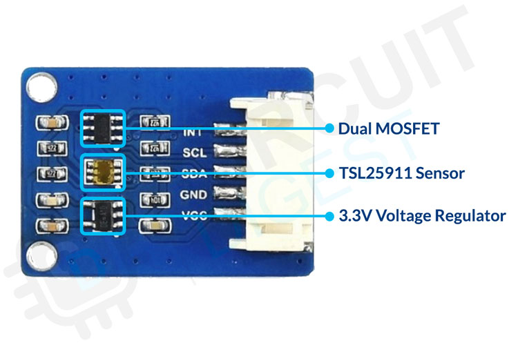
TSL25911 Sensor Module Parts
The TSL25911 sensor module has only very few components, which include the
TSL25911FN AMS chip itself along with the voltage regulator and the level
shifter circuit. You can also find multiple bypass capacitors used to eliminate
any noise in the supply.
 TSL25911 Ambient Light Sensor Module Parts
Commonly Asked Questions
What is the sensitivity of the TSL25911 sensor?
The TSL25911 sensor has a sensitivity of 188µLux.
What are the main benefits of the TSL25911 sensor over other light sensors?
Design flexibility for dark glass and placement
Enables operation in IR light environments
Enables dark room to sunlight operation
Reduces microprocessor interrupt overhead
Improves lux accuracy across various light sources
Where are Ambient light sensors used?
The Ambient light sensors are used, wherever there is a need to measure the
light intensity. Some everyday products use such sensors including smartphones,
laptops, smart watches, etc.
TSL25911 Sensor Module Circuit Diagram
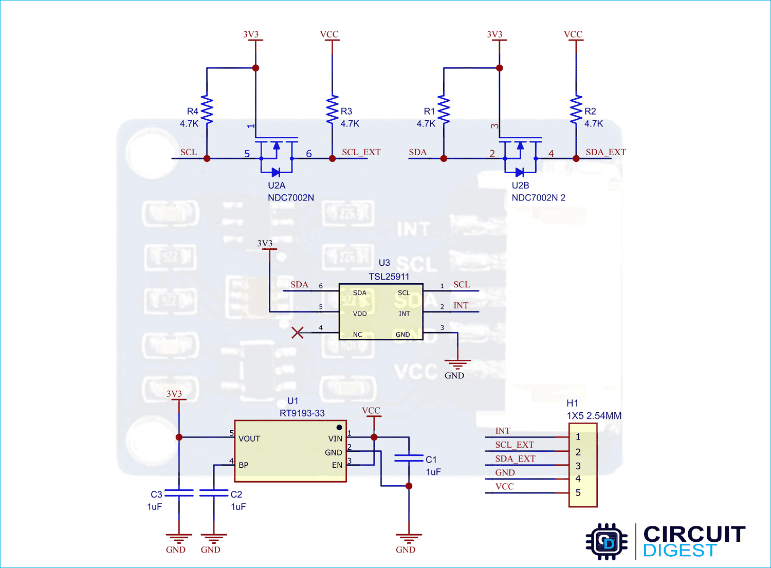
The schematic diagram for the TSL25911 sensor module is given below. As
mentioned earlier, the board has a very low component count. The main components
are the TSL25911 chip and the voltage regulator along with the level shifter
circuit.
 TSL25911 Sensor Module Circuit Diagram
For generating 3.3V for the TSL25911, the RT9193-33 LDO is used. This low
drop-out regulator from Richtek is capable of delivering the current up to
300mA. The RT9193 performance is optimized for battery-powered systems to
deliver ultra-low noise and low quiescent current. A noise bypass pin is
available for further reduction of output noise.
The level shifter circuit is built around the NDC7002N dual N-Channel MOSFET.
This level shifter circuit enables us to use the module with 5V systems and
microcontrollers. You can also find many bypass capacitors on board which are
used to reduce the power supply noise.
TSL25911 Sensor Module Circuit Diagram
For generating 3.3V for the TSL25911, the RT9193-33 LDO is used. This low
drop-out regulator from Richtek is capable of delivering the current up to
300mA. The RT9193 performance is optimized for battery-powered systems to
deliver ultra-low noise and low quiescent current. A noise bypass pin is
available for further reduction of output noise.
The level shifter circuit is built around the NDC7002N dual N-Channel MOSFET.
This level shifter circuit enables us to use the module with 5V systems and
microcontrollers. You can also find many bypass capacitors on board which are
used to reduce the power supply noise.
How does the TSL25911 Sensor Module Works?
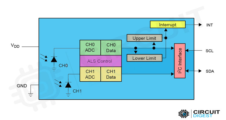
The TSL25911 contains two integrating analog-to-digital converters (ADC) that
integrate currents from two photodiodes. Integration of both channels occurs
simultaneously. Upon completion of the conversion cycle, the conversion result
is transferred to the Channel 0 and Channel 1 data registers, respectively.
The transfers are double buffered to ensure that the integrity of the data is
maintained. After the transfer, the device automatically begins the next
integration cycle. No external circuitry is required for signal conditioning.
Because the output of the device is digital, the output is effectively immune to
noise when compared to an analog signal.
 The TSL2591 also supports an interrupt feature that simplifies and improves
system efficiency by eliminating the need to poll a sensor for a light intensity
value. The primary purpose of the interrupt function is to detect a meaningful
change in light intensity. The concept of a meaningful change can be defined by
the user both in terms of light intensity and time, or persistence, of that
change in intensity. The device has the ability to define two sets of thresholds
, both above and below the current light level. An interrupt is generated when
the value of conversion exceeds either of these limits. One set of thresholds
can be configured to trigger an interrupt only when the ambient light exceeds
them for a configurable amount of time (persistence) while the other set can be
configured to trigger an immediate interrupt. The below image shows the internal
architecture of the TSL25911 sensor chip.
internal architecture of the TSL25911 sensor chip
The TSL2591 also supports an interrupt feature that simplifies and improves
system efficiency by eliminating the need to poll a sensor for a light intensity
value. The primary purpose of the interrupt function is to detect a meaningful
change in light intensity. The concept of a meaningful change can be defined by
the user both in terms of light intensity and time, or persistence, of that
change in intensity. The device has the ability to define two sets of thresholds
, both above and below the current light level. An interrupt is generated when
the value of conversion exceeds either of these limits. One set of thresholds
can be configured to trigger an interrupt only when the ambient light exceeds
them for a configurable amount of time (persistence) while the other set can be
configured to trigger an immediate interrupt. The below image shows the internal
architecture of the TSL25911 sensor chip.
internal architecture of the TSL25911 sensor chip
Circuit Diagram for Interfacing TSL25911 with Arduino
Now that we have completely understood how a TSL25911 ambient light sensor
works, we can connect all the required wires to Arduino and write the code to
get all the data out from the sensor. The following image shows the circuit
diagram for interfacing the TSL25911 ambient light sensor module with Arduino.
Circuit Diagram for Interfacing TSL25911 Sensor with Arduino
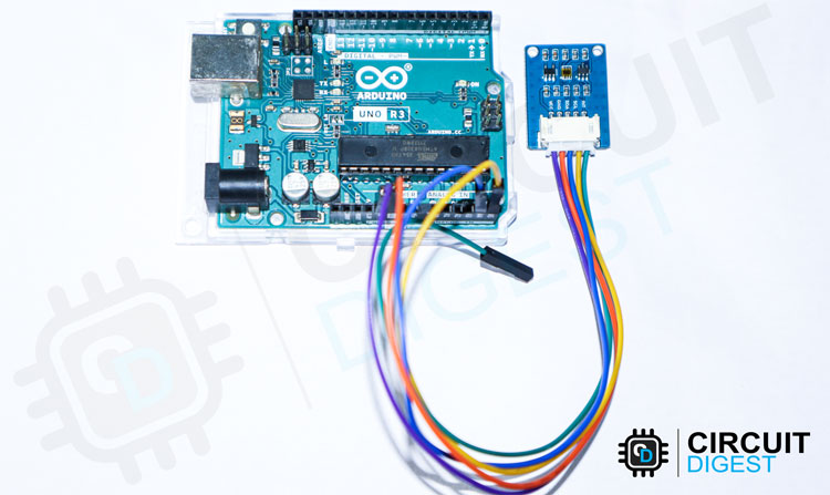
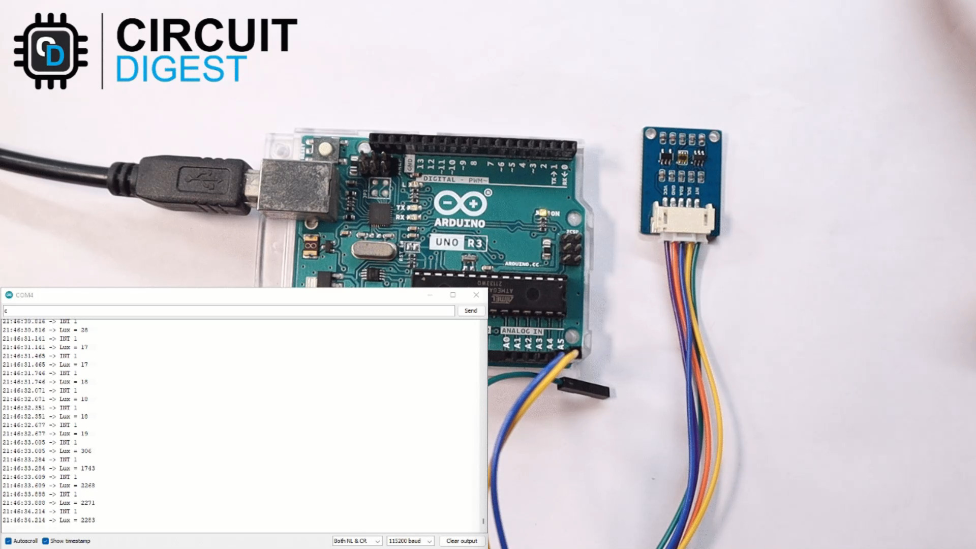
Connections are pretty simple and only require 4 wires. Connect the VCC and GND
of the module to the 5V and GND pins of the Arduino. Then connect the SDA and
SCL pins to the Arduino’s A4 and A5 respectively. Here's how the real-life
connection looks.
Interfacing TSL25911 Sensor with Arduino Circuit
Arduino Code for Interfacing TSL25911 Sensor Module
Once the connections are made, download the code provided in the GitHub link at
the bottom of this page, and extract the sketch file along with all the library
files needed. Compile the code and upload it to Arduino. The code will print
out the sensor reading to the serial monitor.
/*F********************************************************************
*
**********************************************************************/
#include "DEV_Config.h"
#include "TSL2591.h"
//************************* DEFINES ************************************
//************************* PROTOTYPES ************************************
//************************* VARIABLES ************************************
UWORD Lux = 0;
/*F********************************************************************
*
**********************************************************************/
void
setup()
{
DEV_ModuleInit();
Serial.print( "TSL2591_Init\r\n" );
TSL2591_Init();
}
First, we have included the header files for the TSL2591 library. After that, in
the setup function, we initialized the sensor by calling DEV_ModuleInit()
function. The serial port at a baud was initialized with ion the DEV_ModuleInit(
) function. So that we don’t have to initialize it in the setup function.
/*F********************************************************************
*
**********************************************************************/
void
loop()
{
Lux = TSL2591_Read_Lux();
Serial.print( "Lux = " );
Serial.print( Lux );
Serial.print( "\r\n" );
TSL2591_SET_LuxInterrupt( 50, 200 );
}
In the Loop function, we will continuously read the sensor data and will print
it to the serial monitor. The below video shows the TSL25911 sensor interface
in action.
Supporting Files
Code
/*F********************************************************************
*
**********************************************************************/
#include "DEV_Config.h"
#include "TSL2591.h"
//************************* DEFINES ************************************
//************************* PROTOTYPES ************************************
//************************* VARIABLES ************************************
UWORD Lux = 0;
/*F********************************************************************
*
**********************************************************************/
void
setup()
{
DEV_ModuleInit();
Serial.print( "TSL2591_Init\r\n" );
TSL2591_Init();
}
/*F********************************************************************
*
**********************************************************************/
void
loop()
{
Lux = TSL2591_Read_Lux();
Serial.print( "Lux = " );
Serial.print( Lux );
Serial.print( "\r\n" );
TSL2591_SET_LuxInterrupt( 50, 200 );
}