MD_MAX7219xx ESP32
#include <>
https://microcontrollerslab.com/max7219-led-dot-matrix-display-esp8266-nodemcu-tutorial/#google_vignette
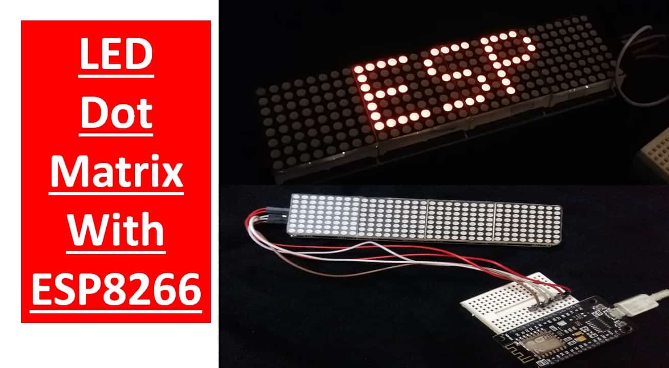
MAX7219 LED Dot Matrix Display with ESP8266 NodeMCU

In this tutorial, we will learn to interface MAX7219 LED Dot matrix display
with ESP8266 NodeMCU. Firstly, we will look into the introduction, pinout of
MAX7219 LED dot matrix display module. It is an LED array used to display
various types of texts, symbols, and images in the form of dots which consists
of LEDs. Through this tutorial, we will familiarize you with the MAX7219 dot
matrix display and program ESP8266 to show various demonstrations of displaying
texts. These will include displaying and scrolling text on the dot matrix.
LED Dot Matrix Display with ESP8266 NodeMCU and MAX7219


We have similar guides with ESP32 and Arduino:

LED Dot Matrix Display with ESP32 and MAX7219
MAX7219 LED Dot Matrix Display Interfacing with Arduino
We have similar guides with ESP32 and Arduino:
LED Dot Matrix Display with ESP32 and MAX7219
MAX7219 LED Dot Matrix Display Interfacing with Arduino
Table of Contents
MAX7219 LED Dot Matrix Display
MAX7219 LED Dot matrix display is one of the popular ones available in the
market and used by students, electronics hobbyists, and especially in industrial
display applications. There are two types of modules generally available. These
are the FC-16 module and the generic module.
MAX7219 led matrix modules
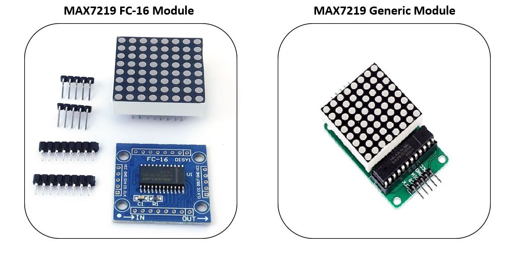 Types of MAX7219 Modules
Each module consists of two units. One is the 8X8 LED dot matrix and the other
is the MAX7219 IC.
Types of MAX7219 Modules
Each module consists of two units. One is the 8X8 LED dot matrix and the other
is the MAX7219 IC.
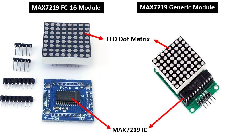 MAX7219 led matrix modules units
You can find more information about MAX7219 here:
MAX7219 led matrix modules units
You can find more information about MAX7219 here:
LED Dot Matrix
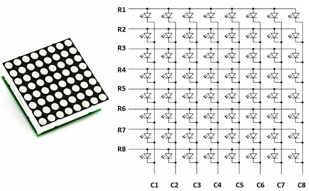
LED dot matrices are available in various dimensions (7×5,8×8, 7×15, etc). The
typical 8×8 LED matrix is shown below which comprises of 64 LEDs, 8 for each row
and column. Each LED is addressed by its row and column number. Each LED is
referred to as a dot.
For making an 8×8 dot matrix all the anodes terminals are connected together in
rows R1 to R8, similarly, the cathodes are connected together in columns C1 to
C8. The reason for connecting all rows and columns together is to save the
required number of pins to control each LED dot. By doing this, the required
number of I/O pins has been reduced to 16. Otherwise, we will need 64 pins to
control an 8×8 LED matrix. This method of controlling a large number of LEDs
with few pins is known as multiplexing.
To Turn on a specific do, we need to apply a positive voltage to the respective
row of that dot and negative or ground to the respective column of that dot. If
the row gets positive voltage and the column gets negative then only a
particular LED will glow.
For example, If you want to glow an LED connected between R2 and C1, we have to
apply 00000010 logic on row R2 and 11111110 on column C1. If R5 is pulled high
and C4 pulled low, then the LED in the fifth row and the fourth column would be
high. Similar logic can also be applied to other rows and columns to turn on and
off each row and column LED. Furthermore, to display text on the dot matrix, we
control each LED very fast speed that the human eye feels like LEDs are
constantly on.
led matrix interfacing
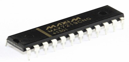
MAX7219 IC
MAX7219 is a common-cathode display driver IC with serial inputs and output
pins. It has an adjustable current capability which can be set using only one
external resistor. In addition to that, it has a four-wire serial interface that
can be easily connected to all microprocessors. It can drive 64 individual LEDs
connected at its output pins using only 4 wires by using the microcontroller.
Furthermore, it can drive dot matrix displays, 7-Segments displays, and bar
graphs.
 MAX7219 8 digit Display Driver IC
On top of that, MAX7219 has a built-in BCD decoder that makes it easy to use
with seven segment numeric displays. Additionally, it has an 8×8 static RAM
that we can use to store numbers. It is one of the most popular displays driver
IC.
MAX7219 8 digit Display Driver IC
On top of that, MAX7219 has a built-in BCD decoder that makes it easy to use
with seven segment numeric displays. Additionally, it has an 8×8 static RAM
that we can use to store numbers. It is one of the most popular displays driver
IC.
Some key features of MAX7219 include:
It is an LED driver display IC with a 10MHz serial interface which allows
the user to select the decode/No-Decode digit.
Its operation is specified in a voltage range of +4.0 to +5.5V. Normally,
the voltage supply of +5V is used.
It provides a feature of digital and analog brightness intensity control and
a 150µA shutdown mode in which the current of all segments is pulled to ground.
It consumes very low power.
The data is displayed on segments with a delay time of 2.2ms.
MAX7219 works well in a temperature range of 0°C to +70°C.
The maximum current for each segment pin is 100mA and for each DIGIT ground
pin is 500mA
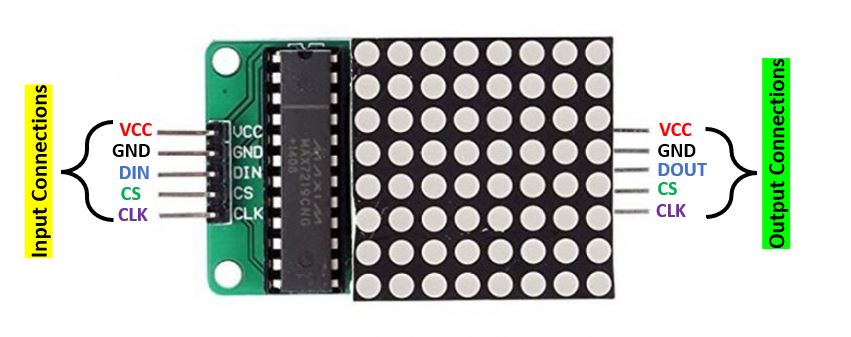
MAX7219 Dot Matrix Module Pinout
The MAX7219 module has 5 terminals consisting of SPI and power supply terminals.
Both types of modules have the same connections on two sides. On one side are
the input connections and on the other side are the output connections Below
you can view the pinout of the generic module.
MAX7219 led matrix pin out
 Pinout of MAX7219 LED Matrix Module
Input Connections
The input connections of the LED matrix are connected with the ESP8266 board.
VCC: This pin supplies power to the MAX7219 module. It is connected with Vin pin of ESP8266 if the brightness is set to half value.
GND: This is the ground pin which should be connected with the ground pin of ESP8266.
DIN: This is the data in pin. It is used as the SPI input to the module.
CS: This is the Chip Select pin for SPI communication.
CLK: This is called the ‘Serial Clock’ pin which is used in SPI serial clock output.
Output Connections
The output connections of the LED matrix are connected with the next module if there is a need to attach more units.
VCC: It is connected to VCC (5V) on the next module
GND: It is connected to the GND on the next module
DOUT: This is the Data out pin. It is connected to DIN pin of the next module.
CS: This is connected to the CS pin of the next module
CLK: This is connected to the CLK pin of the next module
MAX7219 LED Dot Matrix Module
Interfacing with ESP8266
Following components are required:
ESP8266 board
MAX7219 module
Connecting Wires
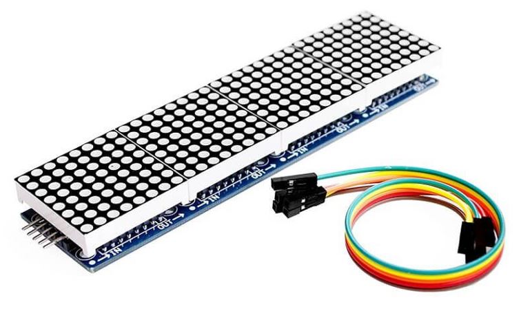
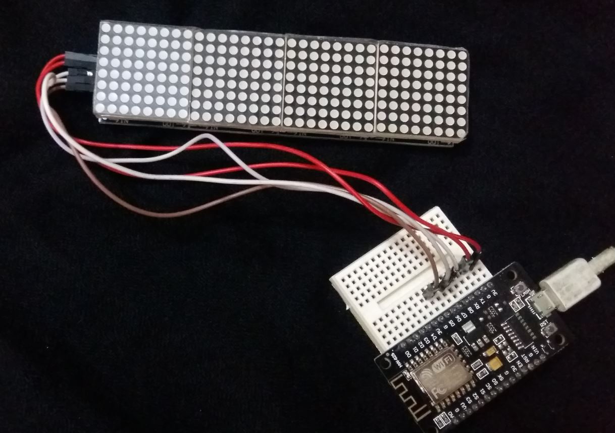
For this project, we will be using the FC-16 module consisting of four units.
MAX7219 led matrix FC-16 module
 Now, we will show you how to connect the MAX7219 module and the ESP8266 board
together. The table below shows the default SPI pins for ESP8266.
Now, we will show you how to connect the MAX7219 module and the ESP8266 board
together. The table below shows the default SPI pins for ESP8266.
| Pin Names | ESP8266 Pin
|
| MOSI | D7 (GPIO13)
|
| MISO | D6 (GPIO12)
|
| SCK | D5 (GPIO14)
|
| CS | D8 (GPIO15)
|
The figure below shows the default SPI pins of ESP8266.
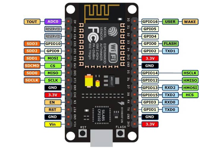 ESP8266 GPIO pins
Now let us see how to connect the MAX7219 module and the ESP8266 board. The table below shows the connections between the two devices:
ESP8266 GPIO pins
Now let us see how to connect the MAX7219 module and the ESP8266 board. The table below shows the connections between the two devices:
| MAX7219 Module | ESP8266
|
| VCC | 3.3V
|
| GND | GND
|
| DIN | D7
|
| CS | D8
|
| CLK | D5
|
As shown from the table, we will connect the VCC terminal of the MAX7219 module
with the 3.3V of the ESP8266 board. This is because we will keep the brightness
of the display at minimum inside the program sketch. Otherwise, use a separate
5V supply. Both grounds will be common. The default SPI GPIO pins of ESP8266
are being used to connect with each of the remaining SPI terminals of the
MAX7219 module.
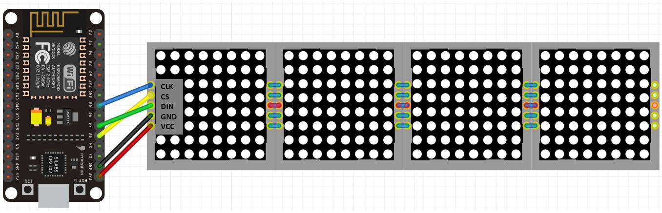 Connection diagram of ESP8266 with MAX7219 module
Installing MAX7219 Arduino Libraries
We will use Arduino IDE to program our ESP8266. Make sure you have the latest
version of the IDE installed in your system. To program our ESP8266 board with
the MAX7219 module we will be required to install two libraries: MD_MAX72XX by
MajicDesigns and MD_Parola. These two libraries will make it very easy to
program our development board.
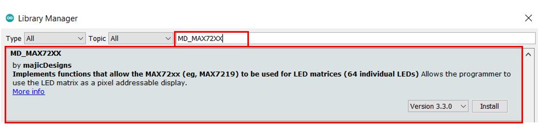
We will use the Arduino Library Manager to install these two libraries. Open
your Arduino IDE and go to Sketch > Library > Manage Libraries. Type ‘MD_MAX72XX’
in the search bar and press enter. Install the library that is highlighted below.
 Instaling MAX-7219 module libraries pic1
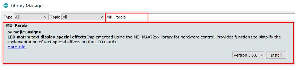
Now type ‘MD_Parola’ in the search bar and press enter. Install the library that is highlighted below.
Instaling MAX-7219 module library MD Parola
Instaling MAX-7219 module libraries pic1
Now type ‘MD_Parola’ in the search bar and press enter. Install the library that is highlighted below.
Instaling MAX-7219 module library MD Parola
 After installing both the libraries, restart your IDE.
ESP8266 with MAX7219 LED Matrix: Arduino Sketches
In this section, we will show you how to use MAX7219 LED matrix with two
sketches. We will be able to print various texts in different alignments on the
LED matrix. Additionally, we will also scroll a simple text from right to left.
MAX7219 Dot Matrix displaying texts Arduino Sketch
Open your Arduino IDE and go to File > New. Copy the code below in that file.
This sketch will display a simple text on the LED matrix in the following
alignments:
Left
Right
Centre
Background invert
You will have to specify your model type and the maximum number of devices (dot
matrix displays) for the sketch given below to work properly.
/*F********************************************************************
*
**********************************************************************/
#include <MD_Parola.h>
#include <MD_MAX72xx.h>
#include <SPI.h>
// Uncomment according to your hardware type
#define HARDWARE_TYPE MD_MAX72XX::FC16_HW
//#define HARDWARE_TYPE MD_MAX72XX::GENERIC_HW
// Defining size, and output pins
#define MAX_DEVICES 4
#define CS_PIN 15
MD_Parola Display = MD_Parola(HARDWARE_TYPE, CS_PIN, MAX_DEVICES);
/*F********************************************************************
*
**********************************************************************/
void
setup()
{
Display.begin();
Display.setIntensity( 0 );
Display.displayClear();
}
/*F********************************************************************
*
**********************************************************************/
void
loop()
{
Display.setTextAlignment( PA_LEFT );
Display.print( "ESP" );
delay( 2000 );
Display.setTextAlignment( PA_CENTER );
Display.print( "ESP" );
delay( 2000 );
Display.setTextAlignment( PA_RIGHT );
Display.print( "ESP" );
delay( 2000 );
Display.setTextAlignment( PA_CENTER );
Display.setInvert( true );
Display.print( "ESP" );
delay( 2000 );
Display.setInvert( false );
delay( 2000 );
}
How the Code Works?
In this part we will discuss how the code works.
Including Libraries
Firstly, we will include all the necessary libraries for this project. We are
including SPI.h as we are using SPI communication protocol between the two
devices. Moreover, we have included the MAX7219 module libraries that we
previously installed for the proper functionality of the LED matrix.
#include <MD_Parola.h>
#include <MD_MAX72xx.h>
#include <SPI.h>
Defining LED matrix type
Secondly, it is very important to define the correct type of MAX7219 LED matrix
that you are using. We are using FC16. If you are using the generic model
instead of FC16 then uncomment the second line and comment the line where we
are defining FC_16HW.
#define HARDWARE_TYPE MD_MAX72XX::FC16_HW
//#define HARDWARE_TYPE MD_MAX72XX::GENERIC_H
Defining number of MAX7219 ICs
Thirdly, we will define the maximum number of ICs in our LED matrix. As we are
using FC16 model thus it consists of four 8×8 LED arrays. Hence our maximum
devices are 4.
#define MAX_DEVICES 4
The next step is to specify the CS pin’s connection with the ESP8266. It is
GPIO pin 15.
#define CS_PIN 15
We will then create an instance of MD_Parola library called ‘Display’ that will
be set to the MD_Parola() function which takes in three arguments. The first
argument is the hardware type. The second argument is the ESP8266 pin connected
with CS. Lastly, the third argument is the number of MAX7219 ICs. We have
defined all of these parameters earlier.
MD_Parola Display = MD_Parola(HARDWARE_TYPE, CS_PIN, MAX_DEVICES);
setup()
Inside the setup() function, we will initialize the LED matrix by using the
begin() function.
Display.begin();
We will set the brightness to a minimum by passing 0 as a parameter inside
setIntensity(). This function takes in values from 0-15 where 15 is the highest
intensity. Moreover, we will clear the display by using displayClear().
Display.setIntensity(0);
Display.displayClear();
loop()
Inside the loop() function we will continuously change the alignment of the text
“ESP.” After every 2 seconds, we will change the alignment of the text.
First we will set the text “ESP” aligned to the left for 2 seconds. This will
be achieved by using setTextAlignment() and passing ‘PA_LEFT’ as a parameter
inside it.
Display.setTextAlignment( PA_LEFT );
Display.print( "ESP" );
delay( 2000 );
Likewise, we will align the ESP text to centre and right as well by passing the
respective alignment as an argument inside the setTextAlignment() function.
Display.setTextAlignment(PA_CENTER);
Display.print("ESP");
delay(2000);
Display.setTextAlignment(PA_RIGHT);
Display.print("ESP");
delay(2000);
Next, we can also invert the display by using the setInvert() function and
passing ‘true’ as a parameter inside it. Moreover, if we pass ‘false’ as an
argument inside the function then the display goes back to its initial one.
Display.setTextAlignment(PA_CENTER);
Display.setInvert(true);
Display.print("ESP");
delay(2000);
Display.setInvert(false);
delay(2000);
Demonstration
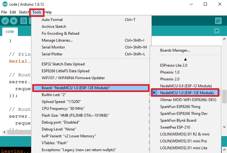
To see the demonstration of the above code, upload the code to the ESP8266
board. But, before uploading code, make sure to select NodeMCU 1.0 from Tools >
Board and also select the correct COM port to which the ESP8266 board is
connected from Tools > Port.
select ESP8266 No deMCU board
 Once the code is uploaded to ESP8266, the LED matrix will start displaying the
text in various alignments.
Watch the video below:
Once the code is uploaded to ESP8266, the LED matrix will start displaying the
text in various alignments.
Watch the video below:
MAX7219 Dot Matrix Arduino Sketch: Scrolling Text
Open your Arduino IDE and go to File > New. Copy the code below in that file.
This sketch will scroll a text from right to left at a set speed.
/*F********************************************************************
*
**********************************************************************/
#include <MD_Parola.h>
#include <MD_MAX72xx.h>
#include <SPI.h>
// Uncomment according to your hardware type
#define HARDWARE_TYPE MD_MAX72XX::FC16_HW
//#define HARDWARE_TYPE MD_MAX72XX::GENERIC_HW
#define MAX_DEVICES 4
#define CS_PIN 15
MD_Parola Display = MD_Parola(HARDWARE_TYPE, CS_PIN, MAX_DEVICES);
/*F********************************************************************
*
**********************************************************************/
void
setup()
{
Display.begin();
Display.setIntensity(0);
Display.displayClear();
Display.displayScroll("SCROLL", PA_RIGHT, PA_SCROLL_LEFT, 150);
}
/*F********************************************************************
*
**********************************************************************/
void
loop()
{
if( Display.displayAnimate() )
Display.displayReset();
}
How does Code Work?
We will discuss the parts where we are incorporating the scrolling feature.
Rest of the code is similar to the one which we discussed above.
setup()
Inside the setup() function, after initializing the LED matrix, setting its
brightness and clearing the display, we will call the displayScroll() function
to set up the scrolling action. This function takes in four arguments. The first
parameter is the text that you want to scroll. In our case the text is ‘SCROLL.’
The second parameter is the alignment of the text in case of a delay. This we
have set to ‘PA_RIGHT’. The third argument is the direction of the scroll. We
have set it to ‘PA_SCROLL_LEFT’ that means the text will scroll towards the left
side. Lastly, the fourth parameter is the time in milliseconds between the text
frames. The higher the value the slower will be the movement of the text.
Display.displayScroll( "SCROLL", PA_RIGHT, PA_SCROLL_LEFT, 150 );
loop()
Inside the loop() function, we will use an if statement with the
displayAnimate() function that will start the scrolling of the text. This will
return true after each scroll is completed then the displayReset() function will
be called to reset the display. Thus, the text scrolls indefinitely.
void
loop()
{
if( Display.displayAnimate())
Display.displayReset();
}
Demonstration
To see the demonstration of the above code, upload the code to ESP8266. But,
before uploading code, make sure to select the ESP8266 board from Tools > Board
and also select the correct COM port to which the ESP8266 board is connected
from Tools > Port.
select ESP8266 NodeMCU board
Once the code is uploaded to ESP8266, the SCROLL text will start scrolling
towards the left side. This will happen continuously.
Conclusion
In conclusion, we have learned to interface MAX7219 dot LED matrix display
module with ESP8266. We have examined two example sketches. These sketches
familiarized us with displaying plain text on the display in various alignments
and also scrolling it at a set speed.
You may also prefer to study other examples on MAX7219:
8×8 LED Matrix Interfacing with MAX7219 and Pic Microcontroller
MAX7219 Interfacing with 8-digit 7 Segment Display and PIC16F877A