| Wiring | Arduino Interface | Led Matrix | 7-Segment Displays |
| Complete Schematic | MAX7219 vs MAX7221 | Selecting RSet | Power Supply Issues |
The MAX72xx uses an SPI interface, and it's Vcc is 5V. On the SPI interface, the MAX72xx only uses MOSI as it's data pin.
The library supports two Maxim IC display drivers, the MAX7219 and the MAX7221 . Both circuits can drive up 64 Leds or a 7-Segment display with 8 digits. The drivers implement a SPI compatible slave interface that can be controlled from the Arduino using only 3 digital output pins. A datasheet for the MAX72XX is available from the Maxim homepage . Both drivers provide identical functions so I will use the generic term MAX72XX for the MAX7221 and the MAX7219 . Both driver chips are still in production as of March 2015.
This section of the documentation focuses on building the external hardware, and should be seen as supplement to the original datasheet . For a basic understanding I suggest you have a look at the datasheet first and the read this section for Arduino specific information
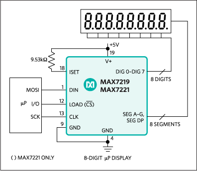
Here is a basic schematic for a MAX72XX , showing only the data signals coming from the Arduino.
Besides the MAX72XX itself and the Leds there are only 3 external components: two capacitors ( C1 ; C2 ) and a resistor ( RSet ).
The capacitors are there to supress noise signals introduced through the power-supply lines. The 2 capacitors should be not ommitted, as it might lead to sporadic or permanent malfunctions. Errors of this type are really hard to track down. Both capacitors must be placed as near as possible to the V+ and the Gnd pins of the MAX72XX .
The resistor RSet is responsible for setting an upper limit on the current that is fed into the Leds. Selecting the correct resistor value might not be trivial. There is an in-depth discussion Selecting RSet on this later.
The MAX72XX has to be powered with +5V . For a single Led-Matrix with 64 Leds it is possible to use the +5V supply from the Arduino-board. If you add more than one matrix to the Arduino you will probably need an external power-supply. More on this in section Power supply issues .
The Gnd -Pins of the MAX72XX has to be connected to one of the Gnd -Pins on the Arduino board so both circuits work on the same voltage-level. The positive power-supply pins ( +5V/Vcc ) can directly be connected to the Arduino-board only for a limited number of Leds.(See Power supply issues for details.)
The three signal lines ( DIn,CLK,Load(/CS) ) can be connected to any three digital outputs of the Arduino board. Just make sure you use the same pin numbers later when you write the Arduino Sketch that drives the Leds.
If you read the datasheet for the MAX72XX you know that the drivers can be cascaded by connecting the signal DOut from one chip to DIn on the next chip. The signals Clk and Load(/CS) have to be connected in parallel to each MAX72XX . There is no strict limit as to how many drivers can be cascaded that way. But the SPI-interface is not capable of any error checking on the transmitted data, so you are already limited with the length of the cables that run from one MAX72XX to the next one. If your cables have to be much longer than 10cm (4 inch) between each MAX72XX you might already run into trouble.
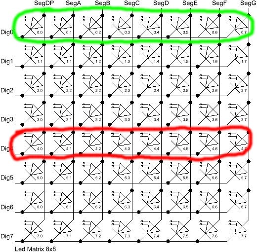
The MAX72XX can drive up an 8x8 matrix as shown in the schematic below. The labels on the left and the top of the schematic refer to the matching pins of the MAX72XX .
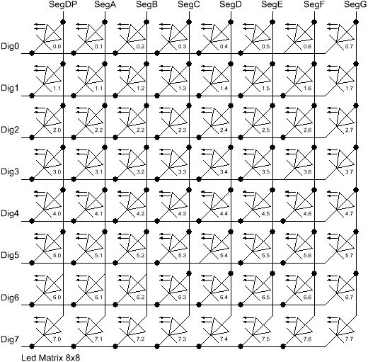
You can build your own matrix using individual Leds, but there are also pre-wired ones available. They can be directly connected to the MAX72XX . Some are arranged as column cathode and some are column anode (as in the diagram above). Either type will work but you must connect the anodes to the Seg lines and cathodes to the Dig lines.
A 7-Segment digit is actually nothing more than 8 Leds ( 7 segments and the dot ) mounted in a special way. For 7-Segment displays only the common cathode -type will work. There is no easy way to make a common anode -type 7-Segment display work with the MAX72XX .
The internal wiring of a common cathode type looks like this
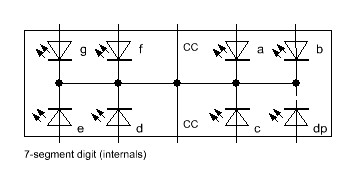
If you look at the matrix schematic again that would resemble one of the rows. The pin-labels on the 7-Segment digits match the name of the pins on a MAX72XX , with the common cathode pin wired to one of the Dig0-7 pins. In most shops you'll find only single 7-Segment digits. But it is very easy to build displays with more digits using the schematic below.
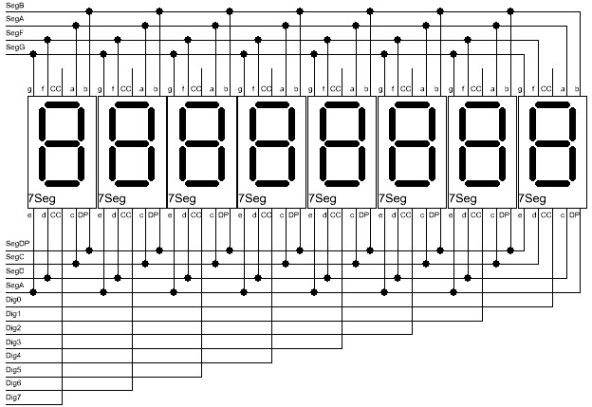
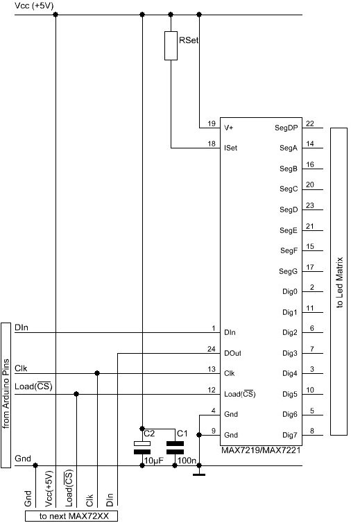
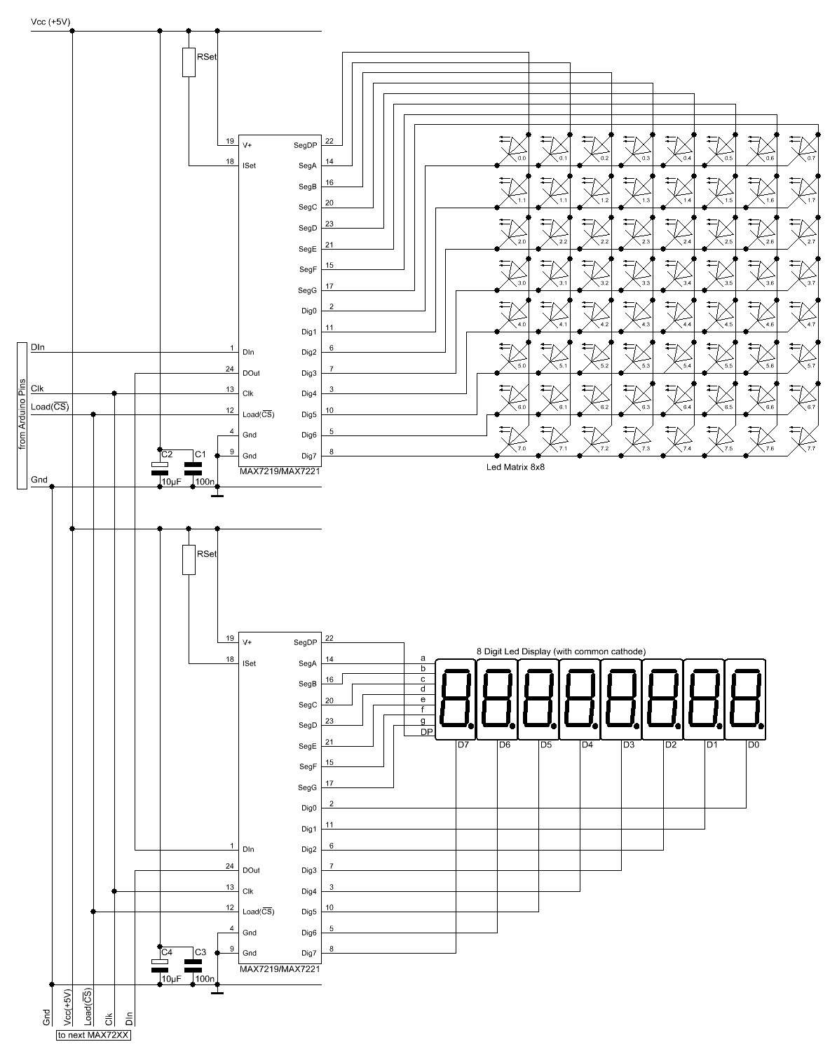
Here is a detailed schematic showing the complete wiring for 2 cascaded MAX72XX . One drives a standard 64 Led-Matrix and the other one a 7-Segment display with 8 digits.
MAX7219 vs. MAX7221 Since there are only minor differences between the MAX7219 and MAX7221 how do you know which one to choose? There are two things to consider here...
MAX7221 supports the standard SPI-protocol so you will have no trouble driving your Led matrix from some other type of controller. This might be another processor board or some type of USB device that can act as SPI-master. The MAX7219 in this regard deviates a little bit from the standards. But on the other hand all the Arduino software and libraries I have seen so far support both devices. If your answer is No here, take the MAX7219 since it is a lot cheaper.
MAX7221
is designed with reduced electromagnetic interference
(
EMI
) in mind.
EMI
could
lead to some jitter in the readings from the
analog inputs of the Arduino or if the Led-Matrix is placed near
some audio circuit it can introduce audible noise to the signal. So,
if your project would go into categories like : audio gadget, audio
levelmeter, (low-)voltage measurement, etc. than go for the
MAX7221
.
In all other cases you should be fine with the
MAX7219
.
RSet
The Arduino forum topics concerning the MAX72XX , often show that there is a fair bit of uncertainty when it comes to selecting a value for the resistor RSet . It is the single component that limits the current fed into all the individual Leds. While some people seem to think of this resistor as a way to control the brightness of the Leds, its real purpose is to protect the MAX72XX and the Leds from exessive currents. Setting the brightness of the display can and should be done from software.
To find out the correct value for RSet you need the datasheet for the MAX72XX and the datasheet for the Ledmatrix or 7-Segment display you're going to use.
From the datasheet of your Led's you will need to know two values
DC forward current
Forward voltage
While the Forward voltage is a fixed value which depends (mostly) on the color of the Led, you have to limit the current going through the Led with resistor
RSet
. Since
DC forward current
is a maximum value,
which is not be exceeded, you should settle for a slightly lower
current. Standard Led's and 7-Segment displays are often rated with a
DC forward current
of 25-30mA. Limiting to 20mA would make a good
choice.
With the information from the Led's datasheet we can now lookup the
resulting value for resistor
RSet
in the table below (which I copied
from the
MAX72XX
datasheet):
Table of the Leds Forward voltages vs. Forward current
| ISeg | 1.5V | 2.0V | 2.5V | 3.0V | 3.5V |
|---|---|---|---|---|---|
| 40mA | 12.2kΩ | 11.8kΩ | 11.0kΩ | 10.6kΩ | 9.69kΩ |
| 30mA | 17.8kΩ | 17.1kΩ | 15.8kΩ | 15.0kΩ | 14.0kΩ |
| 20mA | 29.8kΩ | 28.0kΩ | 25.9kΩ | 24.5kΩ | 22.6kΩ |
| 10mA | 66.7kΩ | 63.7kΩ | 59.3kΩ | 55.4kΩ | 51.2kΩ |
Here is an example: I have a 5x7 dots bright red Led matrix. The datasheet states a Forward voltage of 2.0V. The DC forward current is limited to 25mA. I'll settle for 20mA to stay a bit away from the absolute limits. From the table above, the correct value for RSet would be 28.0k Ω. You might have trouble finding that exact value in shops, but it is always safe to go for higher values. More common values would be 30k Ω or 33k Ω. The Leds will look a bit dimmer with these values, but since it affects all the Led's in the matrix in the same way, you will probably not even notice the difference. It also reduces the supply current which is good news if your project runs on batteries.
Mixing Leds of different colors in a matrix is not really recommended with the MAX72XX . There is only one resistor RSet that limits the current for all the Leds. After you have looked all the different resistors required by your Led colors you will have to settle for the highest value. The brightness of the Leds with different colors will not really match, so it's a ''trial and error'' thing finding the right Leds.
Now that we know how much current is going through one Led in the matrix, the next thing you might ask yourself is : How much current will the whole matrix draw from the power supply?
This really depends on the number of Leds which are lit in a '''row''' of the matrix at the same time. Let's look at the schematic of the Led matrix again. A row is made of 8 Leds the connected cathodes (two of them are marked in the schematic).
Internally the MAX72XX multiplexes the rows of the matrix. Multiplexing means : The drivers switches between the rows of the matrix very fast (about 800 times a second). That gives the impression all the Leds are constantly on, while in reality they just flicker very, very fast. The big advantage of this trick is that at every single point of time no more than 8 Leds (one row) are lit. The maximum current that a single matrix will ever demand is 8 times the current you have set with resistor RSet (+ some 10mA for the MAX72XX itself).
In the example from section Selecting RSet we chose a value that limits the Led current to a maximum of 20mA. If our code lights up all the 64 Leds in the Matrix at the same time, we still have to supply only 170mA, because of multiplexing.
PeakCurrent=(8 x LedCurrent) + MAX72XX-Supply
PeakCurrent=(8 x 20mA) + 10mA = 170mA
If your code never drives more than let's say 4 of the Leds in any of the rows, you will consequently have to supply only half the current.
Depending on the type of USB-hub you're using, there are different limits as to how much current can be drawn from a single USB-port.
The root hubOf the three, only the root and self-powered hubs that supply up to 500mA are recommended. As was said before the actual current your hardware draws depends very much on the software you write.
Here is the worst-case scenario: There are times when all 64 Leds are on at the same time and you selected resistor RSet that allows a current of 20mA per Led. That will add up to a maximum current of 170mA per matrix. With two of these matrices you're at 340mA. Now add another 40mA for the Arduino board itself and you'll end up with 380mA. There is not enough headroom for adding third matrix in this case.
But if you light up only a single Led at any time, your maximum current is at 30mA. You can easily drive 15 MAX72XX and the Arduino from a 500mA hub.
Its hard to come up with numbers as to how long a battery will last. So here are just a few guidelines:
RSet makes the display dimmer, but also reduces the current going through the Leds. Use software features to reduce the brightness of the matrix to a tolerable minimum.
I ran a test with a 9V battery that had a capacity of 625mAH and a Led matrix on which 32 out of the 64 Leds where lit all the time. The whole setup with the matrix and the Arduino (model NG Rev.C) consumed a static current of 78mA. After about 55 minutes all the Leds went off. The voltage on the battery had dropped below 7.4V. The Arduino board itself was still running, but the MAX72XX was not able to drive the Leds any more.