I will refer to the 30 pin as ESP32-30 in order to differentiate between the 30 and 38 pin version.
ESP32-30 Pinout ReferenceTutorial-for-ESP32-Pinout-Reference
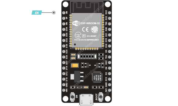
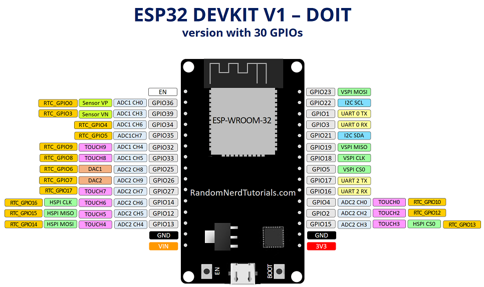
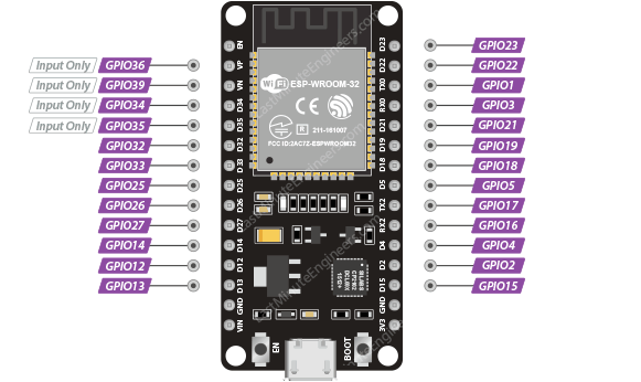
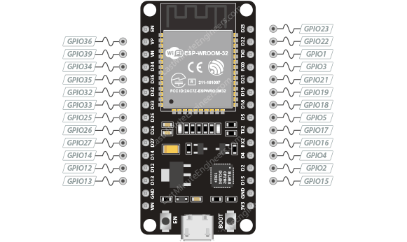
One of the great things about ESP32-30 is that it has a lot more GPIOs than ESP8266. You won’t have to juggle or multiplex your IO pins. There are a few things to watch out for so please read the pinout carefully. Note: Please note that the following pinout reference is for the popular ESP32-30 devkit v1 development board with 30 pins.30pin esp32 dev board Not all pins are broken out in all ESP32-30 development boards, but each specific pin works the same way regardless of the development board you are using.
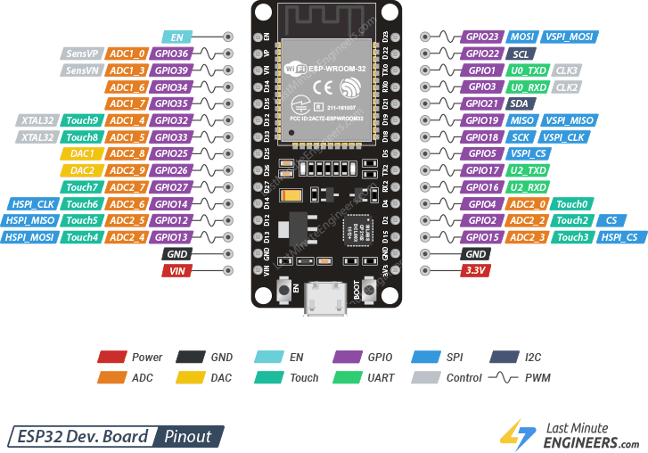
ESP32-30 Peripherals and I/OAlthough the ESP32-30 has total 48 GPIO pins, only 25 of them are broken out to the pin headers on both sides of the development board. These pins can be assigned to all sorts of peripheral duties, including:
| 15 ADC channels | 15 channels of 12-bit SAR ADC’s. The ADC range can be set, in firmware, to either 0-1V, 0-1.4V, 0-2V, or 0-4V |
| 2 UART interfaces | 2 UART interfaces. One is used to load code serially. They feature flow control, and support IrDA too! |
| 25 PWM outputs | 25 channels of PWM pins for dimming LEDs or controlling motors. |
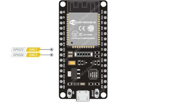
| 2 DAC channels | 8-bit DACs to produce true analog voltages. |
| 3 SPI & 1 I2C interfaces | There are 3 SPI and 1 I2C interfaces to hook up all sorts of sensors and peripherals. |
| 9 Touch Pads | 9 GPIOs feature capacitive touch sensing. |
 esp32 pinout
Let us analyze the ESP32-30 pins and their functions one by one in more detail.
esp32 pinout
Let us analyze the ESP32-30 pins and their functions one by one in more detail.
 esp32 gpio pins
| Label | GPIO | Safe to use? | Reason |
|---|---|---|---|
| D0 | 0 | 🟠 ! | must be HIGH during boot and LOW for programming |
| TX0 | 1 | ⭕ X | Tx pin, used for flashing and debugging |
| D2 | 2 | 🟠 ! | must be LOW during boot and also connected to the on-board LED |
| RX0 | 3 | ⭕ X | Rx pin, used for flashing and debugging |
| D4 | 4 | 🟢 ✓ | |
| D5 | 5 | 🟠 ! | must be HIGH during boot |
| D6 | 6 | ⭕ X | Connected to Flash memory |
| D7 | 7 | ⭕ X | Connected to Flash memory |
| D8 | 8 | ⭕ X | Connected to Flash memory |
| D9 | 9 | ⭕ X | Connected to Flash memory |
| D10 | 10 | ⭕ X | Connected to Flash memory |
| D11 | 11 | ⭕ X | Connected to Flash memory |
| D12 | 12 | must be LOW during boot | |
| D13 | 13 | 🟢 ✓ | |
| D14 | 14 | 🟢 ✓ | |
| D15 | 15 | 🟠 ! | must be HIGH during boot, prevents startup log if pulled LOW |
| RX2 | 16 | 🟢 ✓ | |
| TX2 | 17 | 🟢 ✓ | |
| D18 | 18 | 🟢 ✓ | |
| D19 | 19 | 🟢 ✓ | |
| D21 | 21 | 🟢 ✓ | |
| D22 | 22 | 🟢 ✓ | |
| D23 | 23 | 🟢 ✓ | |
| D25 | 25 | 🟢 ✓ | |
| D26 | 26 | 🟢 ✓ | |
| D27 | 27 | 🟢 ✓ | |
| D32 | 32 | 🟢 ✓ | |
| D33 | 33 | 🟢 ✓ | |
| D34 | 34 | 🟠 ! | Input only GPIO, cannot be configured as output |
| D35 | 35 | 🟠 ! | Input only GPIO, cannot be configured as output |
| VP | 36 | 🟠 ! | Input only GPIO, cannot be configured as output |
| VN | 39 | 🟠 ! | Input only GPIO, cannot be configured as output |
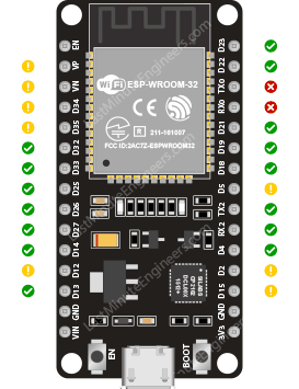 esp32 gpio pins that are safe to use
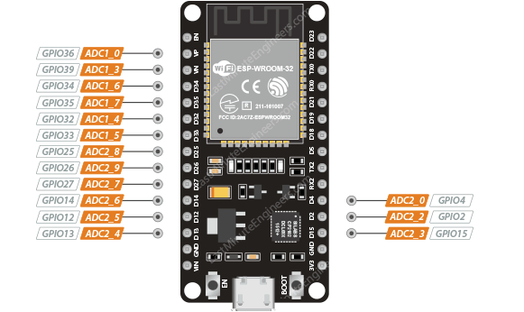 esp32 adc pins
The ADC on the ESP32-30 is a 12-bit ADC meaning it has the ability to detect 4096
(212) discrete analog levels. In other words, it will map input voltages between
0 and the operating voltage 3.3V into integer values between 0 and 4095. For
example, this yields a resolution between readings of: 3.3 volts / 4096 units
or, 0.0008 volts (0.8 mV) per unit.
You also have the ability to set the ADC resolution and ADC range of your
channels in code.
Warning:
The ADC2 pins cannot be used when Wi-Fi is enabled. If your project requires
Wi-Fi, consider using the ADC1 pins instead.
esp32 adc pins
The ADC on the ESP32-30 is a 12-bit ADC meaning it has the ability to detect 4096
(212) discrete analog levels. In other words, it will map input voltages between
0 and the operating voltage 3.3V into integer values between 0 and 4095. For
example, this yields a resolution between readings of: 3.3 volts / 4096 units
or, 0.0008 volts (0.8 mV) per unit.
You also have the ability to set the ADC resolution and ADC range of your
channels in code.
Warning:
The ADC2 pins cannot be used when Wi-Fi is enabled. If your project requires
Wi-Fi, consider using the ADC1 pins instead.
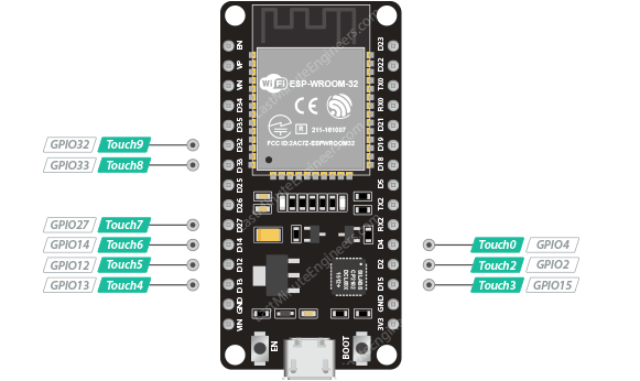 esp32 touch pins
These pins can be easily turned into a touchpad by connecting them to any
conductive object such as wire, thread, foil, cloth, conductive paint, etc. The
low-noise nature of the design and the high sensitivity of the circuit allow
relatively small pads to be used.
These capacitive touch pins can also be used to wake the ESP32-30 from deep sleep.
esp32 touch pins
These pins can be easily turned into a touchpad by connecting them to any
conductive object such as wire, thread, foil, cloth, conductive paint, etc. The
low-noise nature of the design and the high sensitivity of the circuit allow
relatively small pads to be used.
These capacitive touch pins can also be used to wake the ESP32-30 from deep sleep.
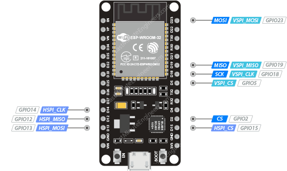 esp32 spi pins
Only VSPI and HSPI are usable SPI interfaces and the third SPI bus is used by
the integrated flash memory chip. Standard libraries usually use VSPI pins
between the two.
HSPI vs. VSPI
Sometimes HSPI is misinterpreted as “Hardware” SPI and VSPI as “Virtual” or
“Software” SPI. Although in reality they all work the same way!
esp32 spi pins
Only VSPI and HSPI are usable SPI interfaces and the third SPI bus is used by
the integrated flash memory chip. Standard libraries usually use VSPI pins
between the two.
HSPI vs. VSPI
Sometimes HSPI is misinterpreted as “Hardware” SPI and VSPI as “Virtual” or
“Software” SPI. Although in reality they all work the same way!
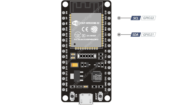 esp32 i2c pins
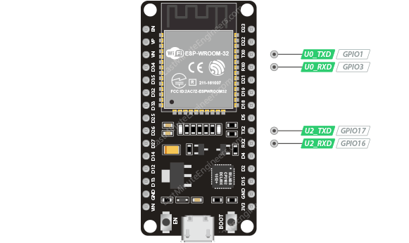 esp32 uart pins
 esp32 pwm pins
The controller consists of PWM timers and the PWM operator. Each timer provides timing in synchronous or independent form, and each PWM operator generates the
waveform for one PWM channel.
esp32 pwm pins
The controller consists of PWM timers and the PWM operator. Each timer provides timing in synchronous or independent form, and each PWM operator generates the
waveform for one PWM channel.
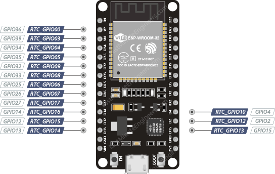 esp32 rtc gpio pins
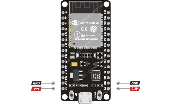 esp32 power pins