Cabinet Lock
We have a cabinet that needs to be secured, at least from children, here is the simple locking mechanism I am building for it.
The mechanism consists of a spring loaded steel slider bar with two steel latches that may be pushed, through a lock, to disengage the latches.
The lock is made from steel angle iron, welded together, the key from steel rods, also welded.
The key must be inserted from the exterior (through 1 1/2" of wood) with the tang and main key shaft alligned vertically then, when the tang hits the back of the lock, rotated 1/4 turn and pushed farther to disengage the latches.
The push block on the end of the slider bar, behind the lock will have a hole for the main key shaft but not the tang which should prevent a round rod pushed through the hole from pushing the slider bar.
I know this is crude, but most of my metal work is.
See lock pics below.
|
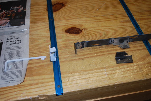
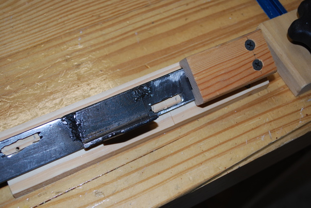
The back end of the slider bar, showing the back latch, slots, and spring.
The slider bar will be mounted on wooden blocks that allow the bar to slide.
The back end of the bar will be held in a block that also contains a spring to push the bar thus engaging the latches.
When the bar is pushed (to the right here) the latches will disengage, allowing the cabinet to be opened.
|
|
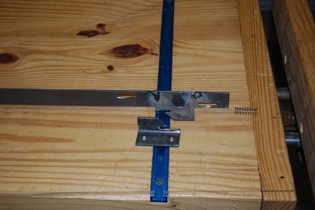
The front end of the slider bar, showing the key, lock, push block on the slide bar, latch.
|
|
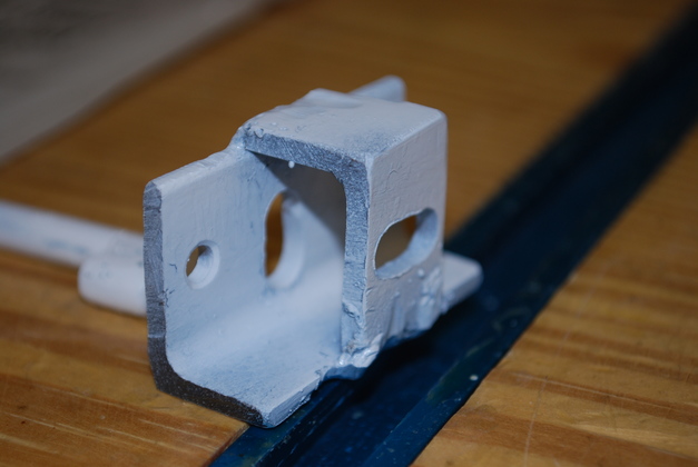
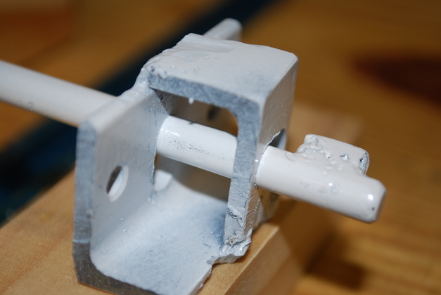
Close up of the back quarter side of the lock, the key can be seen in the background.
The slider bar's push block will normally be against the back of the lock (this side).
The only part of the two holes in the lock that line up are for the main key shaft.
|
|
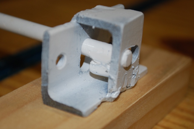
Key inserted into lock.
|
|
The key rotated and pushed through, this would disengage the latches.
|
|
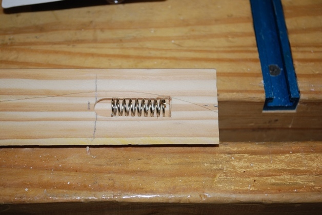
The rear mounting block with the latch spring in it's slot.
|
|
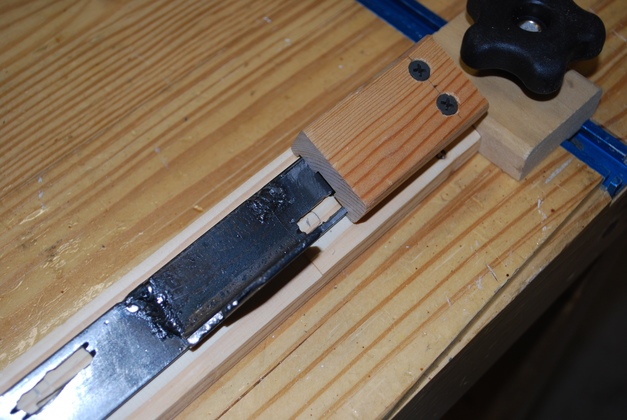
Bar in place on the rear mounting block with spring cover block.
|
|
Bar on rear mounting block with the spring depressed.
|