Note: Both the NPTF and BSPT connectors appear similar, however the two are not interchangeable.

| NPTF | National Pipe Tapered Fuel |
| NPSM | National Pipe Straight Mechanical |
| ISO | International Standards Organization |
| SAE | Society of Automotive Engineers |
| JIC | Joint Industrial Council |
| NFPA | National Fluid Power Association |
| BSP | British Standard Pipe |
| DIN | Deutsche Industrial Norme |
| JIS | Japanese Industrial Standard |
| BSPT | British Standard Pipe Tapered |
| BSPP | British Standard Pipe Parallel |
|
| |||||||||||||||||||||||||||||
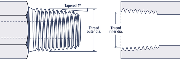
The male and female threads connect and a seal is formed when the two are mated together (i.e. threads deformation). This is known as a dry seal thread. If additional sealing is required, teflon and pipe dope can be applied. The National Fluid Power Association (NFPA) does not recommend the connection for hydraulic applications, however it is commonly found in fluid piping systems
Note: Both the NPTF and BSPT connectors appear similar, however the two are
not
interchangeable.
| Inch size | Dash size | Threads per Inch | Male Thread O.D. (in) | Female thread O.D (in) | ||
| 1 ⁄ 8 | -2 | 27 | 13 ⁄ 32 | 0.41 | 3 ⁄ 8 | 0.38 |
| 1 ⁄ 4 | -4 | 18 | 17 ⁄ 32 | 0.54 | 1 ⁄ 2 | 0.49 |
| 3 ⁄ 8 | -6 | 18 | 11 ⁄ 16 | 0.68 | 5 ⁄ 8 | 0.63 |
| 1 ⁄ 2 | -8 | 14 | 27 ⁄ 32 | 0.84 | 25 ⁄ 32 | 0.77 |
| 3 ⁄ 4 | -12 | 14 | 1 1 ⁄ 16 | 1.05 | 1 | 0.98 |
| 1 | -16 | 11 1 ⁄ 2 | 1 5 ⁄ 16 | 1.32 | 1 1 ⁄ 4 | 1.24 |
| 1 1 ⁄ 4 | -20 | 11 1 ⁄ 2 | 1 21 ⁄ 32 | 1.66 | 1 19 ⁄ 32 | 1.58 |
| 1 1 ⁄ 2 | -24 | 11 1 ⁄ 2 | 1 29 ⁄ 32 | 1.90 | 1 13 ⁄16 | 1.82 |
| 2 | -32 | 11 1 ⁄ 2 | 2 3 ⁄ 8 | 2.38 | 2 5 ⁄ 16 | 2.30 |
Both male and female NSPM connectors' threads are straight, while the male has a 300 internal chamfer, the female has an inverted 300 seat. A mechanical connection is made when the both male and female are mated together. The tapered seat creates a leak-resistant connection, and are commonly found in fluid power systems.
Note: A NPSM female can seal together with a chamfered NPTF male.
| Inch size | Dash size | Threads per Inch | Male Thread O.D. (in) | Female thread O.D (in) | ||
| 1 ⁄ 8 | -2 | 27 | 13 ⁄ 32 | 0.41 | 3 ⁄ 8 | 0.38 |
| 1 ⁄ 4 | -4 | 18 | 17 ⁄ 32 | 0.54 | 1 ⁄ 2 | 0.49 |
| 3 ⁄ 8 | -6 | 14 | 11 ⁄ 16 | 0.68 | 5 ⁄ 8 | 0.63 |
| 1 ⁄ 2 | -8 | 14 | 27 ⁄ 32 | 0.84 | 25 ⁄ 32 | 0.77 |
| 3 ⁄ 4 | -12 | 14 | 1 1 ⁄ 16 | 1.05 | 1 | 0.98 |
| 1 | -16 | 11 1 ⁄ 2 | 1 5 ⁄ 16 | 1.32 | 1 1 ⁄ 4 | 1.24 |
| 1 1 ⁄ 4 | -20 | 11 1 ⁄ 2 | 1 21 ⁄ 32 | 1.66 | 1 19 ⁄ 32 | 1.58 |
| 1 1 ⁄ 2 | -24 | 11 1 ⁄ 2 | 1 29 ⁄ 32 | 1.90 | 1 13 ⁄16 | 1.82 |
| 2 | -32 | 11 1 ⁄ 2 | 2 3 ⁄ 8 | 2.38 | 2 5 ⁄ 16 | 2.30 |
Widely found in hydraulic systems, both the JIC male and JIC female of
this connection have a 37º flare seat as well as straight threads. The
flare seats of the male and female seal together when the straight
threads are joined. The straight threads of the each half hold the
connection together mechanically.
Note: While most SAE J514 threads look identical to SAE 45º flare threads, their seating angles do not match.

| Inch size | Dash size | Thread Size | Male Thread O.D. (in) | Female thread O.D (in) | ||
| 1 ⁄ 8 | -2 | 5 ⁄ 16 - 24 | 5 ⁄ 16 | 0.31 | 9 ⁄ 32 | 0.27 |
| 3 ⁄ 16 | -3 | 3 ⁄ 8 - 24 | 3 ⁄ 8 | 0.38 | 11 ⁄ 32 | 0.34 |
| 1 ⁄ 4 | -4 | 7 ⁄ 16 - 20 | 7 ⁄ 16 | 0.44 | 13 ⁄ 32 | 0.39 |
| 5 ⁄ 16 | -5 | 1 ⁄ 2 - 20 | 1 ⁄ 2 | 0.50 | 15 ⁄ 32 | 0.45 |
| 3 ⁄ 8 | -6 | 9 ⁄ 16 - 18 | 9 ⁄ 16 | 0.56 | 17 ⁄ 32 | 0.51 |
| 1 ⁄ 2 | -8 | 3 ⁄ 4 - 16 | 3 ⁄ 4 | 0.75 | 11 ⁄ 16 | 0.69 |
| 5 ⁄ 8 | -10 | 7 ⁄ 8 - 14 | 7 ⁄ 8 | 0.88 | 13 ⁄ 16 | 0.81 |
| 3 ⁄ 4 | -12 | 1 1 ⁄ 16 - 12 | 11 ⁄ 16 | 1.06 | 1 | 0.98 |
| 7 ⁄ 8 | -14 | 1 3 ⁄ 16 - 12 | 1 3 ⁄ 16 | 1.19 | 1 1 ⁄ 8 | 1.10 |
| 1 | -16 | 1 5 ⁄ 16- 12 | 1 5 ⁄ 16 | 1.31 | 1 1 ⁄ 4 | 1.23 |
| 1 1 ⁄ 4 | -20 | 1 5 ⁄ 8 - 12 | 1 5 ⁄ 8 | 1.63 | 1 9 ⁄ 16 | 1.54 |
| 1 1 ⁄ 2 | -24 | 1 7 ⁄ 8 - 12 | 1 7 ⁄ 8 | 1.88 | 1 13 ⁄ 16 | 1.79 |
| 2 | -32 | 2 1 ⁄ 2 - 12 | 2 1 ⁄ 2 | 2.50 | 2 7 ⁄ 16 | 2.42 |
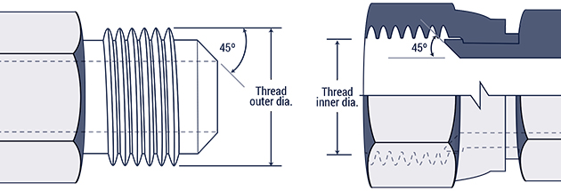
These connectors are widely found in low pressure applications like
refrigerant and fuel lines, as well as automotive piping applications.
Both halves have a 45° flare seat, and the threads of the each connector
engage together to form a tight mechanical connection, with the seal
forming on the 45° flare seat.
Note: SAE 45° Flare connectors are identical to JIC 37° Flare connectors, except for the angles of the seats.
| Inch size | Dash size | Thread Size | Male Thread O.D. (in) | Female thread O.D (in) | ||
| 1 ⁄ 8 | -2 | 5 ⁄ 16 - 24 | 5 ⁄ 16 | 0.31 | 9 ⁄ 32 | 0.27 |
| 3 ⁄ 16 | -3 | 3 ⁄ 8 - 24 | 3 ⁄ 8 | 0.38 | 11 ⁄ 32 | 0.34 |
| 1 ⁄ 4 | -4 | 7 ⁄ 16 - 20 | 7 ⁄ 16 | 0.44 | 13 ⁄ 32 | 0.39 |
| 5 ⁄ 16 | -5 | 1 ⁄ 2 - 20 | 1 ⁄ 2 | 0.50 | 15 ⁄ 32 | 0.45 |
| 3 ⁄ 8 | -6 | 5 ⁄ 8 - 18 | 5 ⁄ 8 | 0.63 | 9 ⁄ 16 | 0.57 |
| 1 ⁄ 2 | -8 | 3 ⁄ 4 - 16 | 3 ⁄ 4 | 0.75 | 11 ⁄ 16 | 0.69 |
| 5 ⁄ 8 | -10 | 7 ⁄ 8 - 14 | 7 ⁄ 8 | 0.88 | 13 ⁄ 16 | 0.81 |
| 3 ⁄ 4 | -12 | 1 1 ⁄ 16 - 14 | 11 ⁄ 16 | 1.06 | 1 | 0.99 |
| 7 ⁄ 8 | -14 | 1 1 ⁄ 4 - 12 | 1 1 ⁄ 4 | 1.25 | 1 5 ⁄ 32 | 1.16 |
| 1 | -16 | 1 3 ⁄ 8 - 12 | 1 3 ⁄ 8 | 1.38 | 1 9 ⁄ 32 | 1.29 |
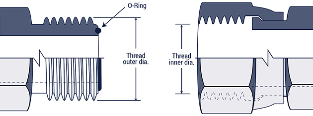
The female port of the O-Ring Boss has a sealing face, chamfer, and a straight thread. The male connector has an O-ring and a straight thread. The seal is made when the O-ring is squeezed into the chamfer. The male and female threads bind together to make a mechanically strong connection. This connection is common in high pressure hydraulic systems.

| Inch size | Dash size | Thread Size | Male Thread O.D. (in) | Female thread O.D (in) | ||
| 1 ⁄ 8 | -2 | 5 ⁄ 16 - 24 | 5 ⁄ 16 | 0.31 | 9 ⁄ 32 | 0.27 |
| 3 ⁄ 16 | -3 | 3 ⁄ 8 - 24 | 3 ⁄ 8 | 0.38 | 11 ⁄ 32 | 0.34 |
| 1 ⁄ 4 | -4 | 7 ⁄ 16 - 20 | 7 ⁄ 16 | 0.44 | 13 ⁄ 32 | 0.39 |
| 5 ⁄ 16 | -5 | 1 ⁄ 2 - 20 | 1 ⁄ 2 | 0.50 | 15 ⁄ 32 | 0.45 |
| 3 ⁄ 8 | -6 | 9 ⁄ 16 - 18 | 9 ⁄ 16 | 0.56 | 17 ⁄ 32 | 0.51 |
| 1 ⁄ 2 | -8 | 3 ⁄ 4 - 16 | 3 ⁄ 4 | 0.75 | 11 ⁄ 16 | 0.69 |
| 5 ⁄ 8 | -10 | 7 ⁄ 8 - 14 | 7 ⁄ 8 | 0.88 | 13 ⁄ 16 | 0.81 |
| 3 ⁄ 4 | -12 | 1 1 ⁄ 16 - 12 | 1 1 ⁄ 16 | 1.06 | 1 | 0.98 |
| 7 ⁄ 8 | -14 | 1 3 ⁄ 16 - 12 | 1 3 ⁄ 16 | 1.19 | 1 1 ⁄ 8 | 1.10 |
| 1 | -16 | 1 5 ⁄ 16 - 12 | 1 5 ⁄ 16 | 1.31 | 1 1 ⁄ 4 | 1.23 |
| 1 1 ⁄ 4 | -20 | 1 5 ⁄ 8 - 12 | 1 5 ⁄ 8 | 1.63 | 1 9 ⁄ 16 | 1.54 |
| 1 1 ⁄ 2 | -24 | 1 7 ⁄ 8 - 12 | 1 7 ⁄ 8 | 1.88 | 1 13 ⁄ 16 | 1.79 |
| 2 | -32 | 2 1 ⁄ 2 - 12 | 2 1 ⁄ 2 | 2.50 | 2 7 ⁄ 16 | 2.42 |
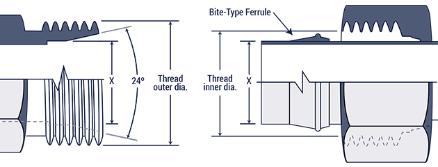
The male half of this connection has a 240 seat with a straight
thread. The female has a compression sleeve with a straight thread.
Along with the sleeve, a female nut and tube partly form the female
connection. With the male half, the seal forms between the 24O seat and
the compression sleeve. With the female half, the seal forms between the
tubing and compression sleeve. The threads mesh together to form a
mechanically strong bond.
| Inch size | Dash size | Thread Size | Male Thread O.D. (in) | Female thread O.D (in) | ||
| 1 ⁄ 8 | -2 | 5 ⁄ 16 - 24 | 5 ⁄ 16 | 0.31 | 9 ⁄ 32 | 0.27 |
| 3 ⁄ 16 | -3 | 3 ⁄ 8 - 24 | 3 ⁄ 8 | 0.38 | 11 ⁄ 32 | 0.34 |
| 1 ⁄ 4 | -4 | 7 ⁄ 16 - 20 | 7 ⁄ 16 | 0.44 | 13 ⁄ 32 | 0.39 |
| 5 ⁄ 16 | -5 | 1 ⁄ 2 - 20 | 1 ⁄ 2 | 0.50 | 15 ⁄ 32 | 0.45 |
| 3 ⁄ 8 | -6 | 9 ⁄ 16 - 18 | 9 ⁄ 16 | 0.56 | 17 ⁄ 32 | 0.51 |
| 1 ⁄ 2 | -8 | 3 ⁄ 4 - 16 | 3 ⁄ 4 | 0.75 | 11 ⁄ 16 | 0.69 |
| 5 ⁄ 8 | -10 | 7 ⁄ 8 - 14 | 7 ⁄ 8 | 0.88 | 13 ⁄ 16 | 0.81 |
| 3 ⁄ 4 | -12 | 1 1 ⁄ 16 - 12 | 11 ⁄ 16 | 1.06 | 1 | 0.98 |
| 7 ⁄ 8 | -14 | 1 3 ⁄ 16 - 12 | 1 3 ⁄ 16 | 1.19 | 1 1 ⁄ 8 | 1.10 |
| 1 | -16 | 1 5 ⁄ 16 - 12 | 1 5 ⁄ 16 | 1.31 | 1 1 ⁄ 4 | 1.23 |
| 1 1 ⁄ 4 | -20 | 1 5 ⁄ 8 - 12 | 1 5 ⁄ 8 | 1.63 | 1 9 ⁄ 16 | 1.54 |
| 1 1 ⁄ 2 | -24 | 1 7 ⁄ 8 - 12 | 1 7 ⁄ 8 | 1.88 | 1 13 ⁄ 16 | 1.79 |
| 2 | -32 | 2 1 ⁄ 2 - 12 | 2 1 ⁄ 2 | 2.50 | 2 7 ⁄ 16 | 2.42 |
This connection forms an impressive leak resistance and can be used in applications up to 6000 psi. The male half of the connection has an O-ring with a straight thread. The female half has a machined flat surface with a straight thread. A seal takes place when the O-ring on the male end is squeezed onto the female flat surface seat. The swivel nut on the female half holds the connection together.
| Inch size | Dash size | Thread Size | Male Thread O.D. (in) | Female thread O.D (in) | ||
| 1 ⁄ 4 | -4 | 9 ⁄ 16 - 18 | 9 ⁄ 16 | 0.56 | 17 ⁄ 32 | 0.51 |
| 3 ⁄ 8 | -6 | 11 ⁄ 16 - 16 | 11 ⁄ 16 | 0.69 | 5 ⁄ 8 | 0.63 |
| 1 ⁄ 2 | -8 | 13 ⁄ 16 - 16 | 13 ⁄ 16 | 0.82 | 3 ⁄ 4 | 0.75 |
| 5 ⁄ 8 | -10 | 1 - 14 | 1 | 1.00 | 15 ⁄ 16 | 0.93 |
| 3 ⁄ 4 | -12 | 1 3 ⁄ 16 - 12 | 13 ⁄ 16 | 1.19 | 1 1 ⁄ 8 | 1.11 |
| 1 | -16 | 1 7 ⁄ 16 - 12 | 1 7 ⁄ 16 | 1.44 | 1 3 ⁄ 4 | 1.36 |
| 1 1 ⁄ 4 | -20 | 1 11 ⁄ 16 - 12 | 1 11 ⁄ 16 | 1.69 | 1 5 ⁄ 8 | 1.61 |
| 1 1 ⁄ 2 | -24 | 2-12 | 2 | 2.00 | 1 15 ⁄ 16 | 1.92 |
Widely used in automotive systems, the inverted flare connection
features a machined male connector with a 420 seat, and a flared male
tubing with a 450 seat. The female side has a 420 seat that provides a
sealing surface. The threads connect together to make a mechanically
strong bond.
| Inch size | Dash size | Thread Size | Male Thread O.D. (in) | Female thread O.D (in) | ||
| 1 ⁄ 8 | -2 | 5 ⁄ 16 - 28 | 5 ⁄ 16 | 0.31 | 9 ⁄ 32 | 0.27 |
| 3 ⁄ 16 | -3 | 3 ⁄ 8 - 24 | 3 ⁄ 8 | 0.38 | 11 ⁄ 32 | 0.34 |
| 1 ⁄ 4 | -4 | 7 ⁄ 16 - 24 | 7 ⁄ 16 | 0.44 | 13 ⁄ 32 | 0.39 |
| 5 ⁄ 16 | -5 | 1 ⁄ 2 - 20 | 1 ⁄ 2 | 0.50 | 15 ⁄ 32 | 0.45 |
| 3 ⁄ 8 | -6 | 5 ⁄ 8 - 18 | 5 ⁄ 8 | 0.63 | 9 ⁄ 16 | 0.57 |
| 7 ⁄ 16 | -7 | 11 ⁄ 16 - 18 | 11 ⁄ 16 | 0.69 | 5 ⁄ 8 | 0.63 |
| 1 ⁄ 2 | -8 | 3 ⁄ 4 - 18 | 3 ⁄ 4 | 0.75 | 23 ⁄ 32 | 0.70 |
| 5 ⁄ 8 | -10 | 7 ⁄ 8 - 18 | 7 ⁄ 8 | 0.88 | 13 ⁄ 16 | 0.81 |
| 3 ⁄ 4 | -12 | 1 1 ⁄ 16 - 16 | 1 1 ⁄ 16 | 1.06 | 1 | 1.00 |
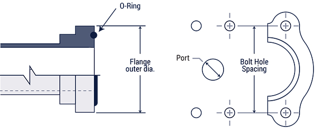
Commonly found in fluid power systems, the Four-Bolt Flange works well connecting 1/2" to 3" hose and tube. The seal forms between the O-ring on the male half and the smooth face of the female port (with t he O-ring seating on the ring groove of the male) . Two clamp halves, held by four bolts, hold the connection together.
These are available in two pressure groups: standard (code 61) and high pressure (code 62).
| Inch size | Dash size | Code 61 Bolt Spacing | Code 61 Flange O.D. | Code 62 Bolt Spacing | Code 62 Flange O.D. |
| 1 ⁄ 2 | -8 | 1 1 ⁄ 2 | 1 3 ⁄ 16 | 1 19 ⁄ 32 | 1 1 ⁄ 4 |
| 3 ⁄ 4 | -12 | 1 7 ⁄ 8 | 1 1 ⁄ 2 | 2 | 1 5 ⁄ 8 |
| 1 | -16 | 2 1 ⁄ 16 | 1 3 ⁄ 4 | 2 1 ⁄ 4 | 1 7 ⁄ 8 |
| 1 1 ⁄ 4 | -20 | 2 5 ⁄ 16 | 2 | 2 5 ⁄ 8 | 2 1 ⁄ 8 |
| 1 1 ⁄ 2 | -24 | 2 3 ⁄ 4 | 2 3 ⁄ 8 | 3 1 ⁄ 8 | 2 1 ⁄ 2 |
| 2 | -32 | 3 1 ⁄ 16 | 2 13 ⁄ 32 | 3 13 ⁄ 16 | 3 1 ⁄ 8 |
| 2 1 ⁄ 2 | -40 | 3 1 ⁄ 2 | 3 5 ⁄ 16 | n/a | n/a |
| 3 | -48 | 4 3 ⁄ 16 | 4 | n/a | n/a |
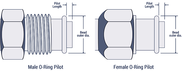
This connection is widely found in automotive and commercial air
conditioning applications. Both male and female halves have a pilot
(could be long or short), and the seal is made when the O-ring is
compressed. Threads tightly mesh together to form a strong mechanical
bond.
| Inch size | Dash size | Male Thread | Female thread | ||
| Thread size | Thread O.D. | Thread size | Thread I.D. | ||
| 3 ⁄ 8 | -6 | 5 ⁄ 8 - 18 | 5 ⁄ 8 | 5 ⁄ 8 - 18 | 9 ⁄ 16 |
| 1 ⁄ 2 | -8 | 3 ⁄ 4 - 18 | 3 ⁄ 4 | 3 ⁄ 4 - 16 | 11 ⁄ 16 |
| 5 ⁄ 8 | -10 | 7 ⁄ 8 - 18 | 7 ⁄ 8 | 7 ⁄ 8 - 14 | 13 ⁄ 16 |
| 3 ⁄ 4 | -12 | 1 1 ⁄ 16 - 16 | 1 1 ⁄ 16 | 1 1 ⁄ 16 - 14 | 1 |
| Inch size | Dash size | Long pilot | Short pilot | ||
| Bead O.D. (in) | Pilot Length (in) | Bead O.D. (in) | Pilot Length (in) | ||
| 3 ⁄ 8 | -6 | 0.52 | 0.28 | 0.52 | 0.19 |
| 1 ⁄ 2 | -8 | 0.64 | 0.39 | 0.64 | 0.19 |
| 5 ⁄ 8 | -10 | 0.77 | 0.39 | 0.77 | 0.19 |
| 3 ⁄ 4 | -12 | 0.91 | 0.39 | 0.91 | 0.19 |
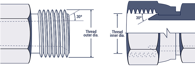
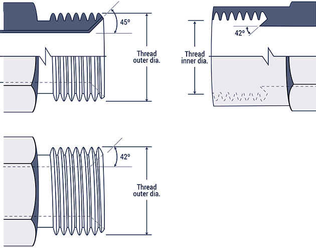
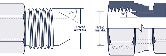
British connections are available in two categories: British Standard Pipe Parallel (BSPP), and British Standard Pipe Tapered (BSPT).
The male end has a 300 seat, which tapered nose of the female swivel makes the seal with.
Note:
Although the male end is comparable to the American National Pipe
Straight Mechanical (NPSM) male, they not interchangeable, due to their
different thread pitches.

| Inch size | Dash size | Thread Size | Male Thread O.D. (in) | Female thread O.D (in) | ||
| 1 ⁄ 8 | -2 | 1 ⁄ 8 - 28 | 3 ⁄ 8 | 0.38 | 11 ⁄ 32 | 0.35 |
| 1 ⁄ 4 | -4 | 1 ⁄ 4 - 19 | 33 ⁄ 64 | 0.52 | 15 ⁄ 32 | 0.47 |
| 3 ⁄ 8 | -6 | 3 ⁄ 8 - 19 | 21 ⁄ 32 | 0.65 | 19 ⁄ 32 | 0.60 |
| 1 ⁄ 2 | -8 | 1 ⁄ 2 - 14 | 13 ⁄ 16 | 0.82 | 3 ⁄ 4 | 0.75 |
| 5 ⁄ 8 | -10 | 5 ⁄ 8 - 14 | 7 ⁄ 8 | 0.88 | 13 ⁄ 16 | 0.80 |
| 3 ⁄ 4 | -12 | 3 ⁄ 4 - 14 | 1 1 ⁄ 32 | 1.04 | 31 ⁄ 32 | 0.97 |
| 1 | -16 | 1 - 11 | 1 5 ⁄ 16 | 1.30 | 1 7 ⁄ 32 | 1.22 |
| 1 1 ⁄ 4 | -20 | 1 1 ⁄ 4 - 11 | 1 21 ⁄ 32 | 1.65 | 1 9 ⁄ 16 | 1.56 |
| 1 1 ⁄ 2 | -24 | 1 1 ⁄ 2 - 11 | 1 7 ⁄ 8 | 1.88 | 1 25 ⁄ 32 | 1.79 |
| 2 | -32 | 2 - 11 | 2 11 ⁄ 32 | 2.35 | 2 1 ⁄ 4 | 2.26 |
The tapered male connects with a tapered female, with the seal forming in the threads.
Note:
Although the BSPT male end is comparable to the National Pipe Tapered
Fuel (NPTF), they are not interchangeable, due to their different size
and thread form.
| Inch size | Dash size | Thread Size | Male Thread O.D. (in) | Female thread O.D (in) | ||
| 1 ⁄ 8 | -2 | 1 ⁄ 8 - 28 | 3 ⁄ 8 | 0.38 | 11 ⁄ 32 | 0.35 |
| 1 ⁄ 4 | -4 | 1 ⁄ 4 - 19 | 33 ⁄ 64 | 0.52 | 15 ⁄ 32 | 0.47 |
| 3 ⁄ 8 | -6 | 3 ⁄ 8 - 19 | 21 ⁄ 32 | 0.65 | 19 ⁄ 32 | 0.60 |
| 1 ⁄ 2 | -8 | 1 ⁄ 2 - 14 | 13 ⁄ 16 | 0.82 | 3 ⁄ 4 | 0.75 |
| 5 ⁄ 8 | -10 | 5 ⁄ 8 - 14 | 7 ⁄ 8 | 0.88 | 13 ⁄ 16 | 0.80 |
| 3 ⁄ 4 | -12 | 3 ⁄ 4 - 14 | 1 1 ⁄ 32 | 1.04 | 31 ⁄ 32 | 0.97 |
| 1 | -16 | 1 - 11 | 1 5 ⁄ 16 | 1.30 | 1 7 ⁄ 32 | 1.22 |
| 1 1 ⁄ 4 | -20 | 1 1 ⁄ 4 - 11 | 1 21 ⁄ 32 | 1.65 | 1 9 ⁄ 16 | 1.56 |
| 1 1 ⁄ 2 | -24 | 1 1 ⁄ 2 - 11 | 1 7 ⁄ 8 | 1.88 | 1 25 ⁄ 32 | 1.79 |
| 2 | -32 | 2 - 11 | 2 11 ⁄ 32 | 2.35 | 2 1 ⁄ 4 | 2.26 |
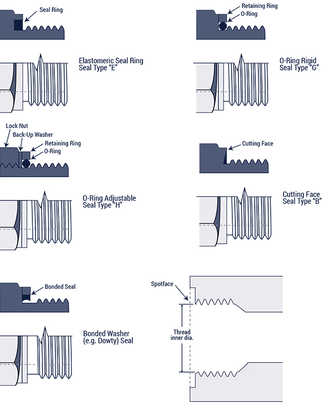
The parallel threads make a seal using a number of different rings or
washers. The seal forms between the male end, and the smooth flat
surface on the female end.
The parallel threads make a seal using a number of different rings or
washers. The seal forms between the male end, and the smooth flat
surface on the female end.
ISO 261 Metric threads
| Metric Thread Size | Male Thread O.D. (mm) | Female Thread I.D (mm) |
| M8 x 1.0 | 8 | 7 |
| M10 x 1.0 | 10 | 9 |
| M12 x 1.5 | 12 | 10.5 |
| M14 x 1.5 | 14 | |
| M16 x 1.5 | 16 | 14.5 |
| M18 x 1.5 | 18 | 16.5 |
| M20 x 1.5 | 20 | 18.5 |
| M22 x 1.5 | 22 | 20.5 |
| M24 x 1.5 | 24 | 22.5 |
| M26 x 1.5 | 24.5 | |
| M27 x 2.0 | 27 | 25 |
| M33 x 2.0 | 33 | 31 |
| M36 x 2.0 | 36 | 34 |
| M42 x 2.0 | 42 | 40 |
| M45 x 2.0 | 45 | 43 |
| M48 x 2.0 | 48 | 46 |
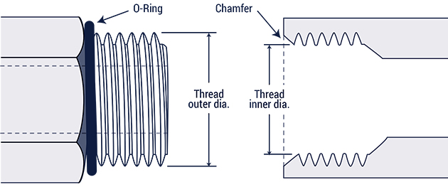
The male half has an O-ring and a straight thread, while the female
half has a machined surface, a chamfer, and a straight thread. The
O-ring on the male half compresses on the chamfer of the female port, to
make the seal. (The ISO 6149 is the same as the SAE J1926-1O-ring Boss,
except the ISO 6149 has metric threads.) The straight threads mesh to
form a strong mechanical bond.
| Metric Thread Size | Male Thread O.D. (mm) | Female Thread I.D (mm) |
| M8 x 1.0 | 8 | 7 |
| M10 x 1.0 | 10 | 9 |
| M12 x 1.5 | 12 | 10.5 |
| M14 x 1.5 | 14 | 12.5 |
| M16 x 1.5 | 16 | 14.5 |
| M18 x 1.5 | 18 | 16.5 |
| M22 x 1.5 | 22 | 20.5 |
| M27 x 2.0 | 27 | 25 |
| M33 x 2.0 | 33 | 31 |
| M42 x 2.0 | 42 | 40 |
| M48 x 2.0 | 48 | 46 |
| M60 x 2.0 | 60 | 58 |
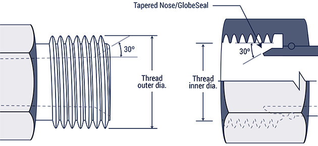
The male connector has a 60° recessed cone and a straight thread; the
female has a straight thread as well, and a globeseal seat. The seal
forms between the recessed cone on the male and the tapered nose of the
female. The threads of both halves mesh to form a strong mechanical
bond. This connection is common in hydraulic systems.
| Pipe/Tube O.D. (mm) | Metric Thread Size | Male Thread O.D. (mm) | Female Thread I.D (mm) |
| 6 | M12 x 1.5 | 12 | 10.5 |
| 8 | M14 x 1.5 | 14 | 12.5 |
| 10 | M16 x 1.5 | 16 | 14.5 |
| 12 | M18 x 1.5 | 18 | 16.5 |
| 15 | M22 x 1.5 | 22 | 20.5 |
| 18 | M26 x 1.5 | 26 | 24.5 |
| 22 | M30 x 1.5 | 30 | 28.5 |
| 28 | M38 x 1.5 | 38 | 36.5 |
| 35 | M45 x 1.5 | 45 | 43.5 |
| 52 | M52 x 1.5 | 52 | 50.5 |
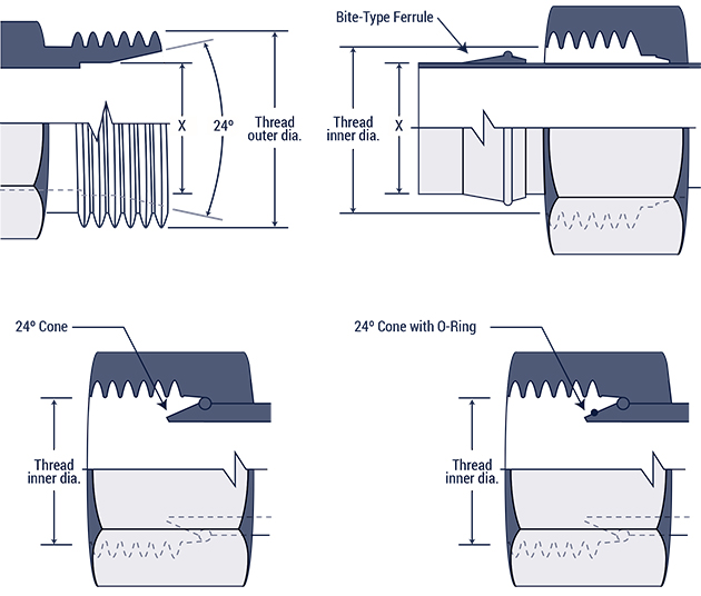
The male connector has a 240 Cone with a straight thread, while the
three female connectors have straight threads with a sealing surface.
The seal forms between the cone on the male and the sealing areas on the
females.
Fittings are available in two categories: DIN 2353 L (light)
and DIN 2353 S (heavy) classes. Each has its own tube sizes and thread
dimensions as shown in the following table:
| DIN 2353 L Tube O.D.(mm) | DIN 2353 S Tube O.D. (mm) | Metric Thread Size | Male Thread O.D. (mm) | Female Thread I.D (mm) |
| 6 | M12 x 1.5 | 12 | 10.5 | |
| 8 | 6 | M14 x 1.5 | 14 | 12.5 |
| 10 | 8 | M16 x 1.5 | 16 | 14.5 |
| 12 | 10 | M18 x 1.5 | 18 | 16.5 |
| 12 | M20 x 1.5 | 20 | 18.5 | |
| 15 | 14 | M22 x 1.5 | 22 | 20.5 |
| 16 | M24 x 1.5 | 24 | 22.5 | |
| 18 | M26 x 1.5 | 26 | 24.5 | |
| 22 | 20 | M30 x 2.0 | 30 | 28 |
| 28 | 25 | M36 x 2.0 | 36 | 34 |
| 30 | M42 x 2.0 | 42 | 40 | |
| 35 | M45 x 2.0 | 45 | 43 | |
| 42 | 38 | M52 x 2.0 | 52 | 50 |
The male half has a 30° seat with a straight thread, while the female
has a 300 seat with a straight thread as well. This connection and the
37° Flare are alike, however it's 30° seat and BSPP-like thread
dimensions make it different from the American 37° Flare.

| Inch size | Dash size | Thread Size | Male Thread O.D. (in) | Female thread O.D (in) | ||
| 1 ⁄ 8 | -2 | 1 ⁄ 8 - 28 | 3 ⁄ 8 | 0.38 | 11 ⁄ 32 | 0.35 |
| 1 ⁄ 4 | -4 | 1 ⁄ 4 - 19 | 33 ⁄ 64 | 0.52 | 15 ⁄ 32 | 0.47 |
| 3 ⁄ 8 | -6 | 3 ⁄ 8 - 19 | 21 ⁄ 32 | 0.65 | 19 ⁄ 32 | 0.60 |
| 1 ⁄ 2 | -8 | 1 ⁄ 2 - 14 | 13 ⁄ 16 | 0.82 | 3 ⁄ 4 | 0.75 |
| 5 ⁄ 8 | -10 | 5 ⁄ 8 - 14 | 7 ⁄ 8 | 0.88 | 13 ⁄ 16 | 0.80 |
| 3 ⁄ 4 | -12 | 3 ⁄ 4 - 14 | 1 1 ⁄ 32 | 1.04 | 31 ⁄ 32 | 0.97 |
| 1 | -16 | 1 - 11 | 1 5 ⁄ 16 | 1.30 | 1 7 ⁄ 32 | 1.22 |
| 1 1 ⁄ 4 | -20 | 1 1 ⁄ 4 - 11 | 1 21 ⁄ 32 | 1.65 | 1 9 ⁄ 16 | 1.56 |
| 1 1 ⁄ 2 | -24 | 1 1 ⁄ 2 - 11 | 1 7 ⁄ 8 | 1.88 | 1 25 ⁄ 32 | 1.79 |
| 2 | -32 | 2 - 11 | 2 11 ⁄ 32 | 2.35 | 2 1 ⁄ 4 | 2.26 |
This connection has parallel metric threads with a 30° seat, and is
common on Komatsu equipment. While the JIS metric connection and the JIS
300 flare are alike, the latter has BSPP-like thread dimensions.
| Dash Size | Metric Thread Size | Male Thread O.D. (mm) | Female Thread I.D (mm) |
| -6 | M18 x 1.5 | 18 | 16.5 |
| -8 | M22 x 1.5 | 22 | 20.5 |
| -10 | M24 x 1.5 | 24 | 22.5 |
| -12 | M30 x 1.5 | 30 | 28.5 |
| -16 | M33 x 1.5 | 33 | 31.5 |
| -20 | M36 x 1.5 | 36 | 34.5 |
| -24 | M42 x 1.5 | 42 | 40.5 |